HEAT GENERATING LIQUID CIRCULATOR
US20250123027A1
2025-04-17
18/504,047
2023-11-07
Smart Summary: A new device helps move liquid while also generating heat. It has a special part that creates movement to circulate the liquid. This part uses one type of electrical power to work. The device is built with a casing that allows liquid to flow in and out. Inside this casing, there is another part that uses the opposite type of electrical power. 🚀 TL;DR
Abstract:
Provided is a heat generating liquid circulator having an improved structural design. A heat generating liquid circulator in accordance with an embodiment of the present disclosure includes a power part configured to generate rotational driving force for liquid circulation and receive power having a single polarity, and a housing having at least one opening through which a liquid flows and configured to accommodate the power part therein and receive power having a polarity opposite to that of the power part.
Applicant:
Interested in similar patents?
Get notified when new applications in this technology area are published.
Description
CROSS-REFERENCE TO RELATED APPLICATION
This application claims priority to Korean Patent Application No. 10-2023-0135924, filed on Oct. 12, 2023, and all the benefits accruing therefrom under 35 U.S.C. § 119, the entire contents of which are incorporated by reference in their entirety.
BACKGROUND
The present disclosure relates to a heat generating liquid circulator, and more particularly, to a heat generating liquid circulator of which performance is improved through a structural design.
A representative device that heats and circulates a liquid is a boiler and is classified into electric type, electrode type, etc., depending on a heating method.
Among these, since electrode bars, to which power having different polarities are applied, are in direct or indirect contact with a liquid to ionize the liquid, the electrode type boiler uses heat generated when the ionized liquid moves to each polarity.
This method using the electrodes to which the power having different polarity are applied is widely used due to its high thermal efficiency, relatively low installation and maintenance costs, and ease of management and control due to its simple structure.
However, this existing method may only generate heat and thus may require a separate circulation device to circulate the liquid. In addition, in the case of the existing method, the heat generating device and the circulation device have be provided in separate spaces, and thus, there is a limitation in that space efficiency and heat circulation speed are reduced.
In addition, in the existing method, one layer structure, which is constituted by a pair of electrode bars to which power having different polarities are applied, is provided, and thus, there is a limitation in that an amount of heat to be generated is insufficient.
SUMMARY
The present disclosure provides a heat generating liquid circulator of which performance is improved through a structural design.
However, the technical problem to be solved by the present disclosure is not limited to the above problem, and other problems not mentioned will be clearly understood by those skilled in the art from the description of the invention described below.
In accordance with an exemplary embodiment of the present invention, a heat generating liquid circulator includes: a power part configured to generate rotational driving force for liquid circulation and receive power having a single polarity; and a housing having at least one opening through which a liquid flows and configured to accommodate the power part therein and receive power having a polarity opposite to that of the power part.
The power part may include: a motor; a shaft connected to the motor to receive power; and a rotor connected to the shaft to rotate.
The housing may include a recess part in which at least a portion of a side surface thereof facing the shaft is recessed.
The opening may be defined in a surface of the recess part, which faces the rotor in a forward and backward direction.
The housing may be configured so that at least one of a surface thereof facing the motor in a forward and backward direction or a surface thereof facing the rotor in the forward and backward direction is opened.
The rotor may include: a rotating shaft connected to the shaft to rotate; and at least one blade interlocked with the rotation of the rotating shaft to rotate, and the housing may further include an extension part which extends to the inside of a surface facing the rotating shaft, to which power is applied through the housing, and which is inserted into the rotating shaft.
The housing may further include a waterproof part accommodated in the housing and coupled to the shaft in a radial direction of the shaft to seal the motor.
The housing may include: a first housing configured to accommodate the power part therein; and a second housing configured to accommodate the first housing therein, wherein a space through which the liquid flows may be defined between the first housing and the second housing.
The second housing may have a plurality of openings in a surface thereof facing the first housing in a forward and backward direction and a radial direction.
The second housing may have at least one opening in each of a pair of surfaces thereof facing the first housing in a forward and backward direction.
The heat generating liquid circulator may further include a power part comprising a first cable and a second cable, which are configured to apply power having polarities opposite to each other, wherein one of the first cable and the second cable may have a protrusion of which one end has a curved surface, and wherein the protrusion may be configured to be in contact with the shaft so as to apply power.
The power part may further include a linear driving part supported on an inner surface of the housing to allow the driving part to move in at least one direction of the forward and backward direction or the radial direction.
The heat generating liquid circulator may further include at least one buffer member provided on an edge of a surface of the housing, which faces the rotor in the forward and backward direction.
The rotor may further include: a rotating shaft connected to the shaft to rotate; at least one blade interlocked with the rotation of the rotating shaft to rotate; and a blade controller configured to adjust at least one of a rotation angle of the blade with respect to a radial direction of the rotating shaft or a rotation angle of the blade with respect to a side surface of the rotating shaft facing an inner surface of the housing in the radial direction of the rotating shaft.
The heat generating liquid circulator may further include a charging part which is accommodated in the housing and in which a coil is provided to generate induced current, wherein the charging part may be connected to the power part to transmit the generated induced current to the power part.
The heat generating liquid circulator may further include a plurality of power parts, wherein the plurality of power parts may be disposed in the same direction.
The heat generating liquid circulator may further include a plurality of power parts, wherein the plurality of power parts may be disposed so that a pair of motors face each other.
The heat generating liquid circulator may further include a plurality of power parts, wherein the plurality of power parts may be disposed so that a pair of rotors face each other, and blades of the two power parts facing each other may be disposed so that blades of the two power parts facing each other are disposed in reverse directions.
In accordance with another exemplary embodiment of the present invention, a heat generating liquid circulator includes: a power part configured to generate rotational driving force for liquid circulation; a heat generating part configured to generate heat; and a housing having at least one opening through which a liquid flows and configured to accommodate the power part and the heat generating part therein.
The heat generating liquid circulator may further include a plurality of power parts, wherein the plurality of power parts may be disposed in the same direction or provided in a pair to face each other.
BRIEF DESCRIPTION OF THE DRAWINGS
Exemplary embodiments can be understood in more detail from the following description taken in conjunction with the accompanying drawings, in which:
FIG. 1 is a perspective view illustrating a heat generating liquid circulator in accordance with an exemplary embodiment of the present disclosure;
FIG. 2 is a cross-sectional view illustrating the heat generating liquid circulator in accordance with an exemplary embodiment of the present disclosure;
FIG. 3 is a cross-sectional view illustrating a heat generating liquid circulator including a recess part in accordance with an exemplary embodiment of the present disclosure;
FIG. 4 is a perspective view illustrating a heat generating liquid circulator in accordance with a second embodiment of the present disclosure;
FIG. 5(a) and FIG. 5(b) are a view for explaining a positional relationship between a rotating shaft and an extension member in a heat generating liquid circulator in accordance with an exemplary embodiment of the present disclosure;
FIG. 6 is a cross-sectional view illustrating a heat generating liquid circulator including a waterproof part in accordance with an exemplary embodiment of the present disclosure;
FIG. 7(a) and FIG. 7(b) are a cross-sectional view illustrating a heat generating liquid circulator including a first housing and a second housing in accordance with an exemplary embodiment and third embodiment of the present disclosure;
FIG. 8(a) and FIG. 8(b) are a view for explaining contact between a power part and a shaft in a heat generating liquid circulator in accordance with an exemplary embodiment and fourth embodiment of the present disclosure;
FIG. 9(a) and FIG. 9(b) are a cross-sectional view illustrating a heat generating liquid circulator including a linear driving part in accordance with an exemplary embodiment and fifth embodiment of the present disclosure;
FIG. 10(a) and FIG. 10(b) are a cross-sectional view illustrating a heat generating liquid circulator including a crank driving device in accordance with sixth and seventh embodiments of the present disclosure;
FIG. 11 is a view illustrating a rotor provided in a heat generating liquid circulator including a blade controller in accordance with an exemplary embodiment of the present disclosure;
FIG. 12 is a cross-sectional view illustrating a heat generating liquid circulator including a charging part in accordance with an exemplary embodiment of the present disclosure;
FIG. 13 is a cross-sectional view illustrating a heat generating liquid circulator in accordance with an eighth embodiment of the present disclosure;
FIG. 14 is a cross-sectional view illustrating a heat generating liquid circulator in accordance with a ninth embodiment of the present disclosure;
FIG. 15 is a cross-sectional view illustrating a heat generating liquid circulator in accordance with a tenth embodiment of the present disclosure;
FIG. 16 is a cross-sectional view illustrating a heat generating liquid circulator in accordance with an eleventh embodiment of the present disclosure;
FIG. 17 is a cross-sectional view illustrating a heat generating liquid circulator in accordance with a twelfth embodiment of the present disclosure;
FIG. 18 is a cross-sectional view illustrating a heat generating liquid circulator in accordance with a thirteenth embodiment of the present disclosure; and
FIG. 19 is a cross-sectional view illustrating a heat generating liquid circulator in accordance with a fourteenth embodiment of the present disclosure.
DETAILED DESCRIPTION OF EMBODIMENTS
Hereinafter, embodiments will be described in detail with reference to the accompanying drawings. The terms used in this specification and claims are not limited to their dictionary meanings, but are merely used to enable a clear and consistent understanding of the invention. Accordingly, it should be apparent to those skilled in the art that the following description of embodiments of the present disclosure is provided for illustration purpose only and not for the purpose of limiting the invention as defined by the appended claims and their equivalents.
Thus, since the embodiments described in this specification and the configurations shown in the drawings are only one most preferred embodiment of the present disclosure and do not represent all of the technical ideas of the present disclosure, it should be understood that there may be various equivalents and modifications that can be substituted for them at the time of this application.
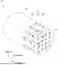
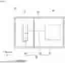
FIG. 1 is a perspective view illustrating a heat generating liquid circulator 10 in accordance with an exemplary embodiment of the present disclosure, and FIG. 2 is a cross-sectional view illustrating the heat generating liquid circulator 10 in accordance with an exemplary embodiment of the present disclosure.
Referring to FIGS. 1 and 2, the heat generating liquid circulator 10 in accordance with an embodiment of the present disclosure may include a housing 100 and a power part 200.
The power part 200 may be configured to generate rotational driving force for liquid circulation and to receive power having a single polarity.
At least one opening 110 through which a liquid flows may be defined in the housing 100. In addition, the housing 100 may be configured to accommodate the power part 200 therein and receive power having a polarity that is opposite to that of the power part 200.
Thus, when the housing 100 and the power part 200 are in contact with the liquid, heat may be generated in the liquid between the power part 200 and an inner surface of the housing 100, to which different polarities are applied.
That is, in the present disclosure, the functions of the heat generating device and the circulation device, which are provided separately in the conventional method, may be performed at the same time in the housing 100 and the power part 200 accommodated within the housing 100. Thus, space efficiency of the heat generating liquid circulator 10 may be improved.
In addition, in the heat generating liquid circulator 10, since heat generation and circulation are performed at the same time at the same position, the heated liquid may be immediately circulated to improve a heat circulation speed of the heat generating liquid circulator 10.
In addition, when compared to the conventional method in which power is applied to the electrode bar having a predetermined area, in the heat generating liquid circulator 10 in accordance with an embodiment of the present disclosure, power may be applied to the housing 100 having a relatively large area and the power part 200 to quickly and uniformly heat the liquid.
Here, the housing 100 may have a cylindrical shape as illustrated in the drawing, but is not limited thereto, and may have various shapes including a polyhedral shape.
In addition, a material of each of the housing 100 and the power part 200 may be a material having high conductivity to allow current to pass therethrough. As an example, the housing 100 may be a conductor based on at least one of aluminum, copper, iron, or tungsten.
In addition, the housing 100 may be made of a material having high light transparency so that current passes through so that the inside of the housing 100 is checked. As an example, the housing 100 may be provided as a transparent electrode containing at least one of ITO, glass, aluminum, or carbon. Thus, the user may check the inside of the housing 100 to visually identify an operation or abnormality of the components accommodated therein.
In addition, the housing 100 and the power part 200 may be configured so that various materials are mixed with each other. As an example, the housing 100 and the power part 200 may be configured so that a conductor and an nonconductor are mixed with each other. Thus, the heat generating liquid circulator 10 may be configured so that only a portion provided as the conductor of the housing 100 and the power part 200 is electrically connected when the power is applied. That is, the housing 100 and the power part 200 may be configured by dividing an arbitrary area into the conductors and the nonconductors to adjust a position and degree at which heat is generated. However, the materials of the housing 100 and the power part 200 are not limited thereto.
In addition, an opening 110 may be defined in a circular shape to pass through the housing 100 as illustrated in FIGS. 1 and 2, but is not limited thereto. As an example, the opening 110 may have various shapes including a polygonal shape.
In addition, the opening 110 may be defined in any component of the heat generating liquid circulator 10 including the housing 100. In addition, when a plurality of openings 110 are defined in the heat generating liquid circulator 10, each of the openings 110 may be defined in a different shape.
In addition, referring to FIGS. 1 and 2, the power part 200 may include a motor 210, a shaft 220, and a rotor 230.
The shaft 220 may be connected to the motor 210 to receive the power.
The rotor 230 may be connected to the shaft 220 to rotate.
Here, power having a polarity opposite to that of the housing 100 may be applied to the rotor 230, and the shaft 220 may be made of an nonconductor. In this case, since no heat is generated in the shaft 220, a wear rate of the shaft 220 may be reduced.
Alternatively, the shaft 220 may be made of a conductor, and the power having the polarity opposite to that of the housing 100 may be applied to the shaft 220 and the rotor 230. In this case, a heating area of the heat generating liquid circulator 10 may increase to increase in amount of heat to be generated.
In addition, a shape of the rotor 230 may be configured as illustrated in the drawing, but is not limited thereto, and an area of the rotating shaft 231 or the number, area, and angle of blades 232, which will be described later, are configured differently to adjust a heat generation area. As an example, the blades 232 of the rotor 230 may be configured to be connected up to side surface to maximize the heat generation area, thereby increasing in heat generation amount of the heat generating liquid circulator 10.
FIG. 3 is a cross-sectional view illustrating the heat generating liquid circulator 10 including a recess part 120 in accordance with an exemplary embodiment of the present disclosure.
Referring to FIG. 3, the housing 100 may include a recess part 120.
The recess part 120 may be defined by recessing at least a portion of a side surface of the housing 100 facing the shaft 220.
Here, the recess part 120 may receive the power having the polarity that is opposite to that of the power part 200 through the housing 100. Thus, the heat generation of the liquid may performed between the rotor 230 and a surface of the recess part 120 that faces the rotor 230 in a forward and backward direction. In addition, the heat generation of the liquid may be performed between the shaft 220 and the surface of the recess part 120 facing in the radial direction of the shaft 220 to increase in heat generation amount of the heat generating liquid circulator 10.
As a position, length, width, shape, etc. of the recess part 120 is changed, a gap and area between the recess part 120, the rotor 230, and the shaft 220, to which power having different polarities are applied, may vary to cause a difference in heat generation amount of the heat generating liquid circulator 10 in accordance with the shape of the recess part 120.
In addition, referring to FIG. 3, the opening 110 may be defined in a surface of the recess part 120 that faces the rotor 230 in the forward and backward direction.
Here, as the rotor 230 rotates, the liquid may flow into the housing 100 through the opening 110 defined in the recess part 120. In addition, the rotor 230 and the recess part 120 may receive the power having opposite polarities, respectively, and thus, the heat may be generated in the liquid between the rotor 230 and the recess part 120. Thus, the introduction of liquid to the inside/outside the housing 100 through the opening 110 defined in the recess part 120, eddy current generated by the flow of the liquid inside/outside the housing 100, or convection current due to the heat generation of the liquid inside the housing 100 may occur to increase in amount of liquid circulation inside/outside the housing 100.
FIG. 4 is a perspective view illustrating a heat generating liquid circulator 10 in accordance with a second embodiment of the present disclosure.
Referring to FIG. 4, a housing 100 may be configured so that at least one of a surface facing the motor 210 in the forward and backward direction and a surface facing the rotor 230 in the forward and backward direction is opened.
Here, the opened shape of the housing 100 is not limited to a specific shape and may vary depending on the purpose of use. As an example, one surface of the housing 100 may be completely opened to maximize the liquid circulation amount as illustrated in the drawing.
As a degree of opening of the housing 100 increases, the liquid circulation amount in the housing 100 may increase. Thus, an appropriate degree of opening and a shape of the housing 100 may be selected in consideration of a desired amount of liquid circulation in the housing 100.
In addition, referring to FIG. 4, the rotor 230 may include at least one through-hole 270 through which the liquid flows.
As illustrated in the drawing, the through-hole 270 may be defined to have a circular cross-section so as to pass through the rotor 230 in the forward and backward direction (more specifically, to pass through a rotating shaft 231, which will be described in detail later). In addition, the through-hole 270 may be defined in a surface of the rotor 230 that faces the motor 210 in the forward and backward direction. Here, when rotational driving force of the power part 200 is generated, the liquid inside the housing 100 may flow through the through-hole 270, and thus, a flow amount of liquid inside/outside the housing 100 in accordance with the rotational driving force of the power part 200 may increase.
FIG. 5 is a view for explaining a positional relationship between a rotating shaft 231 and an extension member 130 in a heat generating liquid circulator in accordance with an exemplary embodiment of the present disclosure.
Referring to FIG. 5, the rotor 230 may include a rotating shaft 231 and at least one blade 232.
The rotating shaft 231 may be connected to the shaft 220 to rotate.
The blade 232 may be configured to rotate to be interlocked with the rotation of the rotating shaft 231.
In addition, the housing 100 may further include the extension member 130.
The extension member 130 may extend from the inside of a surface of the housing 100 facing the rotating shaft 231. In addition, power may be applied to the extension member 130 through the housing 100, and the extension member 130 may be inserted into the rotating shaft 231.
More specifically, the extension member 130 may extend from the housing 100 to receive the power having the same polarity as that of the housing 100 and also may be inserted to be spaced apart from an inner wall of the rotating shaft 231 to which power having a polarity opposite to that of the housing 100 is applied. Therefore, when viewed in a radial direction of the rotor 230, components having polarities that are opposite to the power applied in order of the housing 100, the rotor 230, and the extension member 130 may be arranged alternately to increase in heat generation amount of a heat generating liquid circulator 10.
In addition, a liquid disposed between the extension member 130 and the inner wall of the rotating shaft 231 may generate additional heat when the power having the opposite polarity is applied to the extension member 130 and the rotating shaft 231. Therefore, as the additional heat is generated in the liquid between the extension member 130 and the inner wall of the rotating shaft 231, convection current in the liquid disposed inside/outside the housing 100 may occur to increase in circulation amount of liquid inside/outside the housing 100.
FIG. 6 is a cross-sectional view illustrating a heat generating liquid circulator including a waterproof part in accordance with an exemplary embodiment of the present disclosure.
Referring to FIG. 6, the housing 100 may further include a waterproof part 140.
The waterproof part 140 may be accommodated inside the housing 100 and coupled to the shaft 220 in a radial direction of the shaft 220 to seal the motor 210.
More specifically, when viewed in the forward and backward direction, the opening 110 may not be defined in an area of the housing 100 in which the motor 210 is provided with respect to the waterproof part 140.
Thus, the liquid may not be introduced into a space of the housing 100, which is sealed by the waterproof part 140 and in which the motor 210 is accommodated. Thus, in constructing the heat generating liquid circulator 10, a non-waterproof motor 210 may be used, and other components that are vulnerable to moisture may be disposed in the corresponding space to improve design flexibility and reduce manufacturing costs.
FIG. 7 is a cross-sectional view illustrating a heat generating liquid circulator 10 including a first housing 150 and a second housing 160 in accordance with an exemplary embodiment and third embodiment of the present disclosure.
Referring to FIG. 7, the housing 100 may include the first housing 150 and the second housing 160.
The first housing 150 may be configured to accommodate the power part 200 therein.
The second housing 160 may be configured to accommodate the first housing 150 therein.
In addition, a space S through which a liquid is capable of flowing may be defined between the first housing 150 and the second housing 160.
Here, the second housing 160 may be configured so as not to receive power. Thus, an abrasion rate of the second housing 160 may be reduced, and accidents such as electric shock or burns may be prevented from occurring when a user touches the second housing 160.
(a) of FIG. 7 is a cross-sectional view of the heating liquid circulator 10 including the first housing 150 and the second housing 160 in accordance with an exemplary embodiment of the present disclosure.
Referring to (a) of FIG. 7, the second housing 160 may have a plurality of openings 110 defined in a surface facing the first housing 150 in a forward and backward direction and a radial direction. In this case, a liquid disposed in a space S may flow through the plurality of openings 110 defined in the forward and backward direction and the radial direction in the second housing 160, and thus, a flow amount of liquid inside/outside the second housing 160 may increase.
(b) of FIG. 7 is a cross-sectional view of the heating liquid circulator 10 including the first housing 150 and the second housing 160 in accordance with a third embodiment of the present disclosure.
Referring to (b) of FIG. 7, the second housing 160 has at least one opening 110 in which a pair of surfaces (front and rear surface) facing the first housing 150 are defined in the front and rear directions. In this case, the liquid disposed in the space S may be surrounded by the first housing 150 and the second housing 160 in all directions except for the forward and backward direction, and thus, the flow of the liquid may be concentrated into in the forward and backward direction. Thus, in accordance with the third embodiment of the present disclosure, the flow of the liquid in the space S between the first housing 150 and the second housing 160 may have a relatively constant directionality in the limited space S. That is, performance of the heat generating liquid circulator 10 may be measured more easily by measuring a flow speed of the liquid, a temperature of the liquid, etc. in the space S in accordance with the implemented configuration.
FIG. 8 is a view for explaining contact between a power part 300 and a shaft 220 in a heat generating liquid circulator 10 in accordance with an exemplary embodiment of the present disclosure.
Referring to FIG. 8, the heat generating liquid circulator 10 may further include a power supply part 300.
The power supply part 300 may include a first cable 310 and a second cable 320.
The first cable 310 and the second cable 320 may be configured to apply power having opposite polarities to each other.
(a) of FIG. 8 is a view for explaining a positional relationship between the rotating shaft 300 and the extension member 220 in the heat generating liquid circulator 10 in accordance with an exemplary embodiment of the present disclosure.
Referring to (a) of FIG. 8, one of the first cable 310 and the second cable 320 may be provided with protrusions 311 and 321, each of which has a curved surface at one end.
In addition, each of the protrusions 311 and 321 may be in contact with the shaft 220 to apply power to the shaft 220.
More specifically, each of the protrusions 311 and 321 may be configured so that a portion having a curved surface is in contact with the shaft 220 in consideration of rotation of the shaft 220. As an example, the first cable 310 may be provided with the protrusion 311 having a curved surface at one end. In addition, the protrusion 311 may be configured so that a portion having a curved surface is in contact with the shaft 220 to apply power to the shaft 220. In this case, the second cable 320 may apply power to the housing 100.
Alternatively, the second cable 320 may be provided with the protrusion 321 having a curved surface at one end. In addition, the protrusion 321 may be configured so that a portion having a curved surface is in contact with the shaft 220 to apply power to the shaft 220. In this case, the first cable 310 may apply power to the housing 100.
In addition, as illustrated in (a) of FIG. 8, each of the protrusions 311 and 321 may be inserted into one end of the shaft 220 and may be configured to be in contact with the inner wall of the shaft 220, but is not limited thereto. As an example, the protrusions 311 and 321 may be configured so that ends are in contact with each other without being inserted into the shaft 220 or may be configured to be in contact with a side surface of the shaft 220.
As described above, when the curved portion of each of the protrusions 311 and 321 are configured to be in contact with the shaft 220 so as to apply power to the shaft 220, since the protrusions 311 and 321 are in contact with the shaft 220 to minimize an effect of rotation of the shaft 220, abrasion between the shaft 220 and the protrusions 311 and 321 may be reduced.
Alternatively, one end of the shaft 220 may have a ring-shaped ball joint structure (not shown) surrounding a hemispherical portion of each of the protrusions 311 and 321 to correspond to each of the protrusions 311 and 321. Here, each of the protrusions 311 and 321 may be fitted to be surrounded by a ring-shaped ball joint disposed at one end of the shaft 220.
In this case, since one of the first cable 310 and the second cable 320 is fitted so that each of the protrusions 311 and 321 is surrounded around the ball joint disposed at one end of the shaft 220, the power may be stably applied to the shaft 220 even in vibration and movement of the shaft 220.
(b) of FIG. 8 is a view for explaining a positional relationship between a rotating shaft 300 and an extension member 220 in a heat generating liquid circulator 10 in accordance with a fourth embodiment of the present disclosure.
Referring to (b) of FIG. 8, either the first cable 310 or the second cable 320 may include one of gear parts 312 and 322, each of which is provided with a gear at one end.
In addition, referring to (b) of FIG. 8, a gear coupling part 221 on which a gear is disposed may be disposed on an inner surface of the shaft 220.
In addition, the gear disposed on each of the gear parts 312 and 332 and the gear disposed on the gear coupling part 221 may be configured to be engaged with each other.
Here, when the gear disposed on each of the gear parts 312 and 322 and the gear disposed on the gear coupling part 221 on the inner surface of the shaft 220 are engaged with each other, power may be applied to the shaft 220 from the power supply part 300.
As an example, the first cable 310 may include the gear part 312 provided with the gear at one end. In addition, when the gear disposed on the gear part 312 and the gear disposed on the gear coupling part 221 on the inner surface of the shaft 220 are engaged with each other, power may be applied to the shaft 220 from the power supply part 300. In this case, the second cable 320 may apply power to the housing 100.
Alternatively, the second cable 320 may include the gear part 322 provided with the gear at one end. In addition, when the gear disposed on the gear part 322 and the gear disposed on the gear coupling part 221 on the inner surface of the shaft 220 are engaged with each other, power may be applied to the shaft 220 from the power supply part 300. In this case, the first cable 310 may apply power to the housing 100.
In accordance with the implemented configuration, the power may be stably applied to the shaft 220 even in the vibration or movement of the shaft 220.
FIG. 9 is a cross-sectional view illustrating a heat generating liquid circulator including a linear driving part in accordance with an exemplary embodiment and fifth embodiment of the present disclosure.
Referring to FIG. 9, the power part 200 may further include a linear driving part 240.
The linear driving part 240 may be supported on the inner surface of the housing 100 and be configured to allow the power part 200 to move in at least one of the forward and backward directions or the radial direction.
(a) of FIG. 9 is a cross-sectional view illustrating a heat generating liquid circulator 10 including a linear driving part 240 and a buffer member 400 in accordance with an exemplary embodiment of the present disclosure.
Referring to (a) of FIG. 9, the linear driving part 240 may be supported on a surface of the housing 100 facing the motor 210 in the forward and backward direction. Here, the linear driving part 240 may be configured in the form of at least one linear actuator configured to allow the motor 210 to move in the forward and backward direction. That is, one end of the linear driving part 240 may be coupled to a surface of the housing 100 facing the motor 210 in the forward and backward direction, and the other end of the linear driving part 240 may be coupled to the motor 210.
In addition, in the case of the present disclosure, an amount of heat to be generated may vary depending on a distance between the housing 100 and the power part 200, to which power having different polarities are applied. In the case of this embodiment, the power part 200 may move through the driving of the linear driving part 240 to adjust a gap between the housing 100 and the power part 200, thereby adjusting an amount of heat to be generated of the heat generating liquid circulator 10. Accordingly, even if an installation position and installation angle of the heat generating liquid circulator 10 are changed at an installation place of the heat generating liquid circulator 10, the driving part 200 may move through the driving of the linear driving part 240 so that an optimal gap between the housing 100 and the power part 200 occurs in consideration of the changed installation position of the heat generating liquid circulator 10 to increase in amount of heat to be generated of the heat generating liquid circulator 10.
In addition, the movement of the power part 200 through the driving of the linear driving part 240 itself may generate a flow of the liquid inside/outside the housing 100 to improve the circulation of the liquid inside/outside the housing 100. As a result, when the generation of rotational driving force through the rotor 230 of the power part 200 is limited, the linear movement of the power part 200 in the forward and backward direction through the linear driving part 240 may allow the liquid inside/outside the housing 100 to flow in the forward and backward direction, thereby minimizing deterioration in performance of the heat generating liquid circulator 10.
In addition, referring to (a) of FIG. 9, the heat generating liquid circulator 10 may further include at least one buffer member 400.
The buffer member 400 may be provided at an edge of the surface of the housing 100 facing the rotor 230 in the forward and backward direction.
In addition, the buffer member 400 may prevent the power part 200 and the housing 100 from colliding by the movement due to the rotational driving force or vibration of the power part 200 and the linear movement due to the driving of the linear driving part 240.
In addition, the buffer member 400 may be made of an elastic material such as rubber and may be provided in a shape in which a plurality of polyhedrons protrude as illustrated in the drawing, but is not limited thereto.
(b) of FIG. 9 is a cross-sectional view illustrating a heat generating liquid circulator 10 including a linear driving part 240 in accordance with a fifth embodiment of the present disclosure.
Referring to (b) of FIG. 9, the linear driving part 240 may be supported on a surface of the housing 100, which radially faces the motor 210. At this time, the linear driving part 240 may be configured in the form of at least one linear actuator configured to move the motor 210 in the radial direction of the housing 100. That is, one end of the linear driving part 240 may be coupled to a surface of the housing 100 facing the motor 210 in the radial direction, and the other end of the linear driving part 240 may be coupled to the motor 210.
In addition, the movement of the power part 200 through the driving of the linear driving part 240 itself may generate a flow of the liquid inside/outside the housing 100 to improve the circulation of the liquid inside/outside the housing 100.
FIG. 10 is a cross-sectional view illustrating a heat generating liquid circulator 10 including a crank driving device 250 in accordance with sixth and seventh embodiments of the present disclosure.
Referring to FIG. 10, the heat generating liquid circulator 10 in accordance with the sixth and seventh embodiments of the present disclosure may include a guide member 170, a support member 180, and a crank driving device 250.
The guide member 170 may be configured to suppress the movement of the motor 210 in the radial direction of the housing 100 and guide the movement of the motor 210 in the forward and backward direction. In more detail, the guide member 170 may have a length in the forward and backward direction corresponding to a range of the movement in the forward and backward direction of the motor 210 in accordance with the driving of the crank driving device 250, and at least a portion of the guide member 170 may be in contact with the motor 210 in the radial direction to suppress the movement of the motor 210 in the radial direction and guide the movement of the motor 210 in the forward and backward direction.
The support member 180 may be configured to support the guide member 170 in the radial direction of the housing 100. In more detail, one end of the support member 180 may be coupled to a surface of the housing 100, which radially faces the guide member 170, and the other end may be coupled to the guide member 170.
The crank driving device 250 may be supported on the inner surface of the housing 100 and be configured to allow the power part 200 to move in the forward and backward direction.
In more detail, the crank driving device 250 may include a flywheel 251, a crank shaft 252, a crank arm 253, a connecting rod 254, and a connection member 255.
The flywheel 251 may store rotational energy resulting from driving the crank driving device 250 to prevent sudden speed changes of the crank driving device 250.
The crankshaft 252 may be disposed in a direction perpendicular to the forward and backward direction as its axis and may be connected to a separate servo motor (not shown) to receive power so as to rotate.
The crank arm 253 may be configured to be connected to the crank shaft 252 so as to rotate.
One end of the connecting rod 254 may be connected to the crank arm 253, and the other end may be connected to the connecting member 255. Here, the connecting rod 254 may be connected to the crank arm 253 to rotate and also may transmit power generated by the rotation of the crank arm 253 to the connecting member 255.
One end of the connecting member 255 may be connected to the connecting rod 254, and the other end may be connected to the motor 210. Here, the connecting member 255 may allow the motor 210 to move in the forward and backward direction in accordance with the rotation of the crank arm 253.
That is, the crank driving device 250 may allow the power part 200 to move in the front and rear direction, thereby adjusting a distance between the housing 100 and the power part 200 and adjusting an amount of heat to be generated of the heat generating liquid circulator 10.
In addition, the movement of the power part 200 through the driving of the crank driving device 250 itself may generate a flow of the liquid inside/outside the housing 100 to improve the circulation of the liquid inside/outside the housing 100.
(a) of FIG. 10 is a cross-sectional view illustrating the heat generating liquid circulator 10 including the crank driving device 250 in accordance with the sixth embodiment of the present disclosure.
Referring to (a) of FIG. 10, the power part 200 may further include an insulating member 260.
The insulating member 260 may be provided as an insulator to suppress a flow of current.
In addition, the insulating member 260 may be provided in the form of a circular plate having a groove at a center thereof so as to be spaced a predetermined distance from the shaft 220 in the radial direction of the shaft 220 and spaced a predetermined distance from the housing 100 in the radial direction of the housing 100. Here, at least a portion of the insulating member 260 may be configured to be coupled to the surface of the rotor 230 facing the motor 210. Thus, most of the liquid heated between the housing 100 and the rotor 230, to which power having different polarities are applied, may be circulated in a region of the housing 100, in which the rotor 230 is provided, and outside the housing 100 adjacent thereto with respect to the insulating member 260.
That is, the heat generated by the heat generating liquid circulator 10 and the liquid circulation inside/outside the housing 100 may be mostly generated in the region of the housing 100, in which the rotor 230 is provided, and outside the housing 100 adjacent thereto with respect to the insulating member 260 when viewed in the forward and backward direction. In addition, when viewed in the forward and backward direction, the motor 210, the shaft 220, and the crank driving device 250, which are disposed in the region of the housing 100 provided with the motor 210 with respect to the insulating member 260 may be reduced in abrasion rate due to the liquid heated in the housing 100.
In addition, when the power part 200 moves by driving the crank driving device 250, a flow of the liquid inside/outside the housing 100 due to the movement of the insulating member 260 coupled to the rotor 230 may occur. Thus, the insulating member 260 may improve the liquid circulation inside/outside the housing 100.
(b) of FIG. 10 is a cross-sectional view illustrating the heat generating liquid circulator 10 including the crank driving device 250 in accordance with the seventh embodiment of the present disclosure.
Referring to (b) of FIG. 10, the housing 100 may further include an insulating part 190.
The insulating part 190 may be provided as an insulating material to suppress a flow of current.
In addition, the insulating part 190 may be spaced a predetermined distance from the shaft 220 in the radial direction of the shaft 220 and may be coupled to a surface of the housing 100, which faces the shaft 220 in the radial direction. Here, when an end of the insulating part 190 is viewed in the forward and backward direction, the insulating part 190 may be disposed in the region of the housing 100, in which the motor 210 is provided with respect to the rotor 230 so as not to interfere with the driving range of the rotor 230 in the forward and backward direction due to the driving of the crank driving device 250. Thus, most of the liquid heated between the housing 100 and the rotor 230, to which power having different polarities are applied, may be circulated in a region of the housing 100, in which the rotor 230 is provided, and outside the housing 100 adjacent thereto with respect to the insulating part 190 when viewed in the forward and backward direction.
That is, the heat generated by the heat generating liquid circulator 10 and the liquid circulation inside/outside the housing 100 may be mostly generated in the region of the housing 100, in which the rotor 230 is provided, and outside the housing 100 adjacent thereto with respect to the insulating part 190 when viewed in the forward and backward direction. In addition, when viewed in the forward and backward direction, the motor 210, the shaft 220, and the crank driving device 250, which are disposed in the region of the housing 100 provided with the motor 210 with respect to the insulating part 190 may be reduced in abrasion rate due to the heated liquid.
FIG. 11 is a view illustrating the rotor 230 provided in the heat generating liquid circulator 10 including a blade controller 233 in accordance with an exemplary embodiment of the present disclosure.
Referring to FIG. 11, the rotor 230 may further include a blade controller 233.
In addition, the blade controller 233 may be configured to adjust at least one of a rotation angle of the blade 232 with respect to the radial direction of the rotating shaft 231 or a rotation angle of the blade 232 with respect to a side surface of the rotating shaft 231 facing an inner surface of the housing 100 in the radial direction of the rotating shaft 231.
In more detail, the blade controller 233 may include a first blade controller 233a and a second blade controller 233b.
The first blade controller 233a may be configured in the form of a motor to allow the blade 232 to rotate with respect to the radial direction of the rotating shaft 231. Thus, the blade 232 may rotate in the same direction as the rotation direction of the motor of the first blade controller 233a.
That is, the blade controller 233 may adjust the rotation of the motor of the first blade controller 233a to adjust the rotation angle of the blade 232 in the radial direction of the rotating shaft 231.
The second blade controller 233b may include a guide rail 2331, a rail coupling member 2332, and a linear driving device 2333.
Here, the first blade controller 233a may be rotatably coupled to the rotating shaft 231 to be rotatable with respect to a side surface of the rotating shaft 231, which faces the inner surface of the housing 100 in the radial direction of the rotating shaft 231. Here, when external force is applied to the first blade controller 233a by the second blade controller 233b, the first blade controller 233a may rotate with respect to the side surface of the rotating shaft 231 facing the inner surface of the housing 100 in the radial direction of the rotating shaft 231 in the state of being coupled to the rotating shaft 231.
The guide rail 2331 may be coupled in the radial direction of the rotating shaft 231 with respect to an inner surface of the rotating shaft 231.
The rail coupling member 2332 may be configured to have one end coupled to the linear driving device 2333 and the other end coupled to the guide rail 2331 so as to move along the guide rail 2331.
The linear driving device 2333 may be configured in the form of a linear actuator to enable linear movement through extension and contraction. In addition, one end of the linear driving device 2333 may be coupled to the first blade controller 233a, and the other end may be coupled to the rail coupling member 2332. This linear driving device 2333 may be driven by a separate servo motor (not shown).
Here, when the linear driving device 2333 extends, the rail coupling member 2332 may move in the radial direction of the rotating shaft 231 along the guide rail 2331. In addition, as the rail coupling member 2332 moves, the linear driving device 2333 may rotate with respect to the side surface of the rotating shaft 231 facing the inner surface of the housing 100 in the radial direction of the rotating shaft 231. In addition, as the linear driving device 2333 rotates, the first blade controller 233a coupled to the linear driving device 2333 and the blade 232 coupled to the first blade controller 233a may rotate.
Alternatively, when the linear driving device 2333 is contracted, the rail coupling member 2332 may move along the guide rail 2331 in a direction that is opposite to a direction in which the linear driving device 2333 extends. Additionally, the blade 232 may rotate in the direction that is opposite to that when the linear driving device 2333 extends.
That is, the blade controller 233 may adjust the extension and contraction of the linear driving device 2333 to adjust the rotation angle of the blade 232 with respect to the side surface of the rotating shaft 231 facing the inner surface of the housing 100 in the radial direction of the rotating shaft 231.
In addition, the blade 232 may be curved in the radial direction of the rotating shaft 231 and may be configured to have a bent shape. Thus, when the rotation angle of the blade 232 is changed, an amount and direction by which the rotor 230 provided in the heat generating liquid circulator 10 pushes a liquid may be changed.
In addition, power having opposite polarities may be applied to the blade 232 and the housing 100. Thus, an amount of heat generated by the heat generating liquid circulator 10 may vary depending on a gap and facing area between the blade 232 and the housing 100. Here, the blade 232 may be configured to be curved in the radial direction of the rotating shaft 231 and thus have a curved shape. Since the radial direction of the rotating shaft 231 is the same as the radial direction of the housing 100, when the rotation angle of the blade 232 is changed, the gap and facing area between the blade 232 and the housing 100 may be changed.
Thus, the rotation angle of the blade 232 may be adjusted through the blade controller 233 to adjust the amount of heat to be generated of the heat generating liquid circulator 10 and the flow rate and flow direction of the liquid.
FIG. 12 is a cross-sectional view illustrating a heat generating liquid circulator 10 including a charging part 500 in accordance with an exemplary embodiment of the present disclosure.
Referring to FIG. 12, the heat generating liquid circulator 10 may further include the charging part 500.
The charging part 500 may be accommodated inside the housing 100 and may be configured to generate induced current by providing a coil therein. In addition, the charging part 500 may be connected to the power part 200 to transmit the generated induced current to the power part 200.
In more detail, in the charging part 500, when current flows into a transmission coil configured to correspond to the coil provided inside the charging part 500 so as to generate the induced current from the outside, magnetic fields may be generated in the transmission coil, and current may be generated using a magnetic induction method in which electricity is induced in the coil inside the charging part 500 corresponding to the transmission coil due to an influence of the magnetic fields to generate induced current.
That is, since the heat generating liquid circulator 10 charges the current wirelessly through the charging part 500, there may be no need to provide a separate charging cable for charging in a wired manner, and a limitation such as limited current charging or current leakage due to disconnection or damage of the charging cable may be prevented from occurring.
Here, the charging part 500 may be provided on the inner surface of the housing 100 in consideration of a distance from the externally disposed transmission coil. Alternatively, the charging part 500 may be provided to be adjacent to the power part 200 or may be accommodated inside the power part 200 in consideration of the current transmission to the power part 200.
FIGS. 13 to 15 are cross-sectional views illustrating a heat generating liquid circulator 10 in accordance with eighth to tenth embodiments of the present disclosure.
Referring to FIGS. 13 to 15, the heat generating liquid circulator 10 may include a plurality of power parts 200.
In accordance with the implemented configurations, the heat generating liquid circulator 10 may include the plurality of power parts 200 to increase in flow amount of liquid inside/outside the housing 100.
In addition, the power part 200 may be configured to receive power having a polarity opposite to that of the housing 100. In addition, the heat generating liquid circulator 10 may include the plurality of power parts 200, and thus, when compared to the case the heat generating liquid circulator 10 include the single power part 200, the power part 200 to which power is applied may increase in area. Thus, in the heat generating liquid circulator 10, a space between the power part 200 and the housing 100, in which heat generation of a liquid is generated, may be widened to increase in amount of heat to be generated.
Referring to FIG. 13, the plurality of power parts 200 may be disposed to face the same direction.
In more detail, the heat generating liquid circulator 10 may increase in flow rate of the liquid inside/outside the housing 100 by disposing the plurality of power parts 200 to face the same direction.
Referring to FIG. 14, the plurality of power parts 200 may be provided in a pair so that the motors 210 face each other.
In more detail, in the heat generating liquid circulator 10, a plurality of power parts 200 may be provided in a pair so that the motors 210 are disposed to face each other, and thus, the plurality of rotors 230 provided in the plurality of power parts 200 may be disposed to be adjacent to and face the housing 100, thereby increasing in heat generation amount of the heating liquid circulator 10.
Referring to FIG. 15, the plurality of power parts 200 may be disposed in a pair so that the rotors 230 face each other, and the blades 232 of the two power parts 200 facing each other may be disposed in opposite directions.
In the heat generating liquid circulator 10, when the power parts 200 having the same structure are disposed to face each other, shapes and rotation directions of the rotor 230 provided in the power part 200 may be the same, and thus, the liquid may flow in the opposite directions.
In order to solve this limitation, the heat generating liquid circulator 10 may be configured so that the directions of the blades 232 of the pair of power parts 200 facing each other are opposite to each other, and thus, the pair of power parts 200 facing each other may be configured to allow the liquid to flow in the same direction. Thus, a flow rate of the liquid inside/outside the housing 100 may increase.
Alternatively, the heat generating liquid circulator 10 may be configured so that the motors 210 of the pair of power parts 200 facing each other may rotate in opposite directions, and thus, the pair of power parts 200 facing each other may be configured to allow the fluid to flow in the same direction. Thus, a flow rate of the liquid inside/outside the housing 100 may increase.
FIG. 16 is a cross-sectional view illustrating a heat generating liquid circulator 1010 in accordance with an eleventh embodiment of the present disclosure.
Referring to FIG. 16, the heat generating liquid circulator 1010 in accordance with another embodiment of the present disclosure may include a housing 1100, a power part 1200, and a heat generating part 1300.
The power part 1200 may be configured to generate rotational driving force for liquid circulation.
The heat generating part 1300 may be configured to generate heat.
At least one opening 1110 through which a liquid flows may be defined in the housing 1100. In addition, the housing 1100 may be configured to accommodate the power part 1200 and the heat generating part 1300 therein.
That is, like the heat generating liquid circulator 10 in accordance with an embodiment of the present disclosure, the heat generating liquid circulator 1010 may be configured so that heat generation of the liquid is performed using the heat generating part 1300 provided in the heat generating liquid circulator 1010, rather than applying power having opposite polarities to the housing 100 and the power part 200 to allow the liquid to generate heat.
Thus, since the power is not applied to the housing 1100 and the power part 1200 in the heat generating liquid circulator 1010, an abrasion rate of the housing 1100 and the power part 1200 may be reduced. In addition, since the power is not applied to the housing 1100, accidents such as electric shock or burns may be prevented from occurring when a user touches the housing 1100.
The power part 1200 may include a motor 1210, a shaft 1220, and a rotor 1230.
The shaft 1220 may be connected to the motor 1210 to receive the power.
The rotor 1230 may be configured to be connected to the shaft 1220 so as to rotate.
The heat generating part 1300 may use a heating method through electrode heat generators to which power having different polarities are applied, but is not limited thereto. As an example, the heat generating part 1300 may allow the liquid to generate heat by using a heating method using electrical resistance or a heating method using a separate fuel.
In addition, as illustrated in the drawing, the heat generating part 1300 may be disposed to face the motor 1210 in the forward and backward direction, but is not limited thereto. As an example, the heat generating part 1300 may be disposed to face the rotor 1230 in the forward and backward direction or may be disposed to be offset from the power part 1200 in a vertical direction.
In addition, the heat generating part 1300 may be configured to adjust whether or not heat is generated and an amount of heat to be generated. Here, the heat generating part 1300 may be provided with a printed circuit board (PCB) therein to determine whether or not to generate heat and to adjust the amount of heat to be generated.
In addition, the heat generating liquid circulator 1010 may include a plurality of heat generating parts 1300 to increase in heat generating area and amount of heat to be generated. Here, the heat generating liquid circulator 1010 may quickly heat the liquid inside by simultaneously generating heat through the plurality of heat generating parts 1300 or may adjust the amount of heat to be generated by gradually generating heat through the plurality of heat generating parts 1300.
In addition, the heat generating liquid circulator 1010 may include a configuration corresponding to the configuration of the heat generating liquid circulator 10 in accordance with the foregoing embodiment of the present disclosure. As an example, the heat generating liquid circulator 1010 may include a waterproof part, a first housing, a second housing, a rotating shaft, a blade, a blade controller, a linear driving part, a buffer member, and a charging part, which correspond to the configurations of the heat generating liquid circulator 10 in accordance with an embodiment of the present disclosure.
FIGS. 17 to 19 are cross-sectional views illustrating a heat generating liquid circulator 1010 in accordance with a twelfth to fourteenth embodiment of the present disclosure.
Referring to FIGS. 17 to 19, the heat generating liquid circulator 1010 may include a plurality of power parts 1200.
Thus, the heat generating liquid circulator 1010 may include the plurality of power parts 1200 to increase in flow amount of liquid inside/outside the housing 1100.
In addition, the plurality of power parts 1200 may be disposed to face the same direction or may be disposed in a pair to face each other.
Here, as illustrated in FIG. 17, the heat generating liquid circulator 1010 may increase in flow rate of the liquid by disposing the plurality of power parts 1200 to face the same direction.
Alternatively, as illustrated in FIG. 18, in the heat generating liquid circulator 1010, the plurality of power parts 1200 may be provided in a pair so that the motors 1210 face each other, and thus, the flow direction of the liquid inside/outside the housing 1100 may be dispersed to increase in flow rate of the liquid inside/outside the housing 1100.
Alternatively, as illustrated in FIG. 19, in the heat generating liquid circulator 1010, the plurality of power parts 1200 may be provided in a pair so that the rotors 1230 face each other, and the blades of the two power parts 1200 facing each other are disposed in reverse directions. As a result, a flow rate of the liquid may be maximized between the rotors 1230 of the pair of power parts 1200 facing each other. Thus, the heat generating liquid circulator 1010 may in increase flow rate of the liquid, and the heat generating part 1300 may be disposed between the rotors 1230 of the pair of power parts 1200 facing each other so that the heated liquid is rapidly circulated inside/outside the housing 1100.
Here, the heat generating part 1300 may be disposed at a central portion of the housing 1100 as illustrated in FIGS. 17 to 19, but is not limited thereto. As an example, the heat generating part 1300 may be disposed to face the rotor 1230 or the motor 1210, which is provided in one of the plurality of power parts 1200 in the forward and backward direction, and thus, the heated liquid may be quickly circulated inside/outside the housing 1100.
The heat generating liquid circulator in accordance with the embodiment of the present disclosure may be improved in performance by applying the power having the different polarities to the power part that circulates the liquid and the housing that accommodates the power part, rather than using the separate electrode bar.
In more detail, the heat generating device and circulating device, which are separately provided in the conventional method may be performed at the same time in the housing and the power part accommodated in the housing in accordance with the embodiment of the present disclosure to improve the space efficiency of the heat generating liquid circulator.
In addition, in accordance with the present disclosure, since the generation and circulation of the heat of the liquid are performed at the same time and at the same position, the heated liquid may be directly circulated to improve the heat circulation speed of the heat generating liquid circulator.
In addition, several other additional effects may be achieved by various embodiments of the present disclosure. The various effects of the present disclosure will be described in detail in each embodiment, or descriptions of effects that can be easily understood by those skilled in the art will be omitted.
As described above, while the embodiments of the present disclosure have been described with reference to the specific embodiments, it will be apparent to those skilled in the art that various changes and modifications may be made without departing from the spirit and scope of the invention as defined in the following claims.
Claims
What is claimed is:1. A heat generating liquid circulator comprising:
a power part configured to generate rotational driving force for liquid circulation and receive power having a single polarity; and
a housing having at least one opening through which a liquid flows and configured to accommodate the power part therein and receive power having a polarity opposite to that of the power part.
2. The heat generating liquid circulator of claim 1, wherein the power part comprises:
a motor;
a shaft connected to the motor to receive power; and
a rotor connected to the shaft to rotate.
3. The heat generating liquid circulator of claim 2, wherein the housing comprises a recess part in which at least a portion of a side surface thereof facing the shaft is recessed.
4. The heat generating liquid circulator of claim 3, wherein the opening is defined in a surface of the recess part, which faces the rotor in a forward and backward direction.
5. The heat generating liquid circulator of claim 2, wherein the housing is configured so that at least one of a surface thereof facing the motor in a forward and backward direction or a surface thereof facing the rotor in the forward and backward direction is opened.
6. The heat generating liquid circulator of claim 2, wherein the rotor comprises:
a rotating shaft connected to the shaft to rotate; and
at least one blade interlocked with the rotation of the rotating shaft to rotate, and
the housing further comprises an extension part which extends to the inside of a surface facing the rotating shaft, to which power is applied through the housing, and which is inserted into the rotating shaft.
7. The heat generating liquid circulator of claim 2, wherein the housing further comprises a waterproof part accommodated in the housing and coupled to the shaft in a radial direction of the shaft to seal the motor.
8. The heat generating liquid circulator of claim 1, wherein the housing comprises:
a first housing configured to accommodate the power part therein; and
a second housing configured to accommodate the first housing therein,
wherein a space through which the liquid flows is defined between the first housing and the second housing.
9. The heat generating liquid circulator of claim 8, wherein the second housing has a plurality of openings in a surface thereof facing the first housing in a forward and backward direction and a radial direction.
10. The heat generating liquid circulator of claim 8, wherein the second housing has at least one opening in each of a pair of surfaces thereof facing the first housing in a forward and backward direction.
11. The heat generating liquid circulator of claim 2, further comprising a power part comprising a first cable and a second cable, which are configured to apply power having polarities opposite to each other,
wherein one of the first cable and the second cable has a protrusion of which one end has a curved surface, and
wherein the protrusion is configured to be in contact with the shaft so as to apply power.
12. The heat generating liquid circulator of claim 2, wherein the power part further comprising a linear driving part supported on an inner surface of the housing to allow the driving part to move in at least one direction of the forward and backward direction or the radial direction.
13. The heat generating liquid circulator of claim 12, further comprising at least one buffer member provided on an edge of a surface of the housing, which faces the rotor in the forward and backward direction.
14. The heat generating liquid circulator of claim 2, wherein the rotor further comprises:
a rotating shaft connected to the shaft to rotate;
at least one blade interlocked with the rotation of the rotating shaft to rotate; and
a blade controller configured to adjust at least one of a rotation angle of the blade with respect to a radial direction of the rotating shaft or a rotation angle of the blade with respect to a side surface of the rotating shaft facing an inner surface of the housing in the radial direction of the rotating shaft.
15. The heat generating liquid circulator of claim 1, further comprising a charging part which is accommodated in the housing and in which a coil is provided to generate induced current,
wherein the charging part is connected to the power part to transmit the generated induced current to the power part.
16. The heat generating liquid circulator of claim 2, further comprising a plurality of power parts,
wherein the plurality of power parts are disposed in the same direction.
17. The heat generating liquid circulator of claim 2, further comprising a plurality of power parts,
wherein the plurality of power parts are disposed so that a pair of motors face each other.
18. The heat generating liquid circulator of claim 2, further comprising a plurality of power parts,
wherein the plurality of power parts are disposed so that a pair of rotors face each other, and
blades of the two power parts facing each other are disposed so that blades of the two power parts facing each other are disposed in reverse directions.
19. A heat generating liquid circulator comprising:
a power part configured to generate rotational driving force for liquid circulation;
a heat generating part configured to generate heat; and
a housing having at least one opening through which a liquid flows and configured to accommodate the power part and the heat generating part therein.
20. The heat generating liquid circulator of claim 19, further comprising a plurality of power 5 parts,
wherein the plurality of power parts are disposed in the same direction or provided in a pair to face each other.
Images & Drawings included:


Sources:
- United States Patent and Trademark Office - verify current appl. status at the USPTO↗
Similar patent applications:
Recent applications in this class:
- » 20250109887 2025-04-03
WATER HEATER APPLIANCE AND HEAT TRANSFER ASSEMBLY - » 20250035339 2025-01-30
GAS WATER HEATER - » 20240175603 2024-05-30
Blower Collar for Combustion System - » 20240093906 2024-03-21
WATER HEATER RECOVERY TIME ESTIMATION - » 20210364191 2021-11-25
Pressure compensation and mixing device - » 20210095889 2021-04-01
Filter assembly structure and water heater including the same - » 20200318856 2020-10-08
Housing assembly and water heater - » 20190390874 2019-12-26
Heat exchanger and water heater including same - » 20180372374 2018-12-27
Gas feed tube assembly for a water heater - » 20170363321 2017-12-21
Pressure compensation and mixing device having a mixing unit and a pressure compensation unit