ATOMIZER AND ELECTRONIC ATOMIZING DEVICE
US20250127232A1
2025-04-24
18/981,555
2024-12-15
Smart Summary: An atomizer is a device that helps turn liquid into a fine mist. It has an outer wall and a special part called the atomizing core assembly inside it. The outer wall has an opening for liquid to enter, while the core has small holes for the liquid to pass through. These holes and the space between the outer wall and the core work together to create a path for the liquid to flow. This design allows the liquid to be efficiently transformed into vapor. 🚀 TL;DR
Abstract:
An atomizer and an electronic atomizing device are provided. The atomizer includes an outer wall and an atomizing core assembly. The outer wall defines a first liquid inlet. The atomizing core assembly is at least partially arranged inside the outer wall, and includes a sleeve. The sleeve defines a plurality of fluid passage holes. The sleeve is at least partially arranged radially inside the outer wall, and configured to jointly define a capillary gap with the outer wall. Each of the first liquid inlet and the fluid passage holes is connected to the capillary gap, and define a fluid path from any of the plurality of fluid passage holes directly through the capillary gap to the first liquid inlet.
Inventors:
- Wei Li 177 🇨🇳 Shenzhen, China
- Yisong WEI 6 🇨🇳 Shenzhen, China
- Zhong Luo 10 🇨🇳 Shenzhen, China
- Chaoyong BIE 3 🇨🇳 Shenzhen, China
- Haidong ZHU 3 🇨🇳 Shenzhen, China
- Aping ZHOU 3 🇨🇳 Shenzhen, China
Assignee:
- SHENZHEN SMOORE TECHNOLOGY LIMITED 139 🇨🇳 Shenzhen, China
Applicant:
Interested in similar patents?
Get notified when new applications in this technology area are published.
Classification:
A24F40/485 » CPC main
Electrically operated smoking devices; Component parts thereof; Manufacture thereof; Maintenance or testing thereof; Charging means specially adapted therefor; Constructional details, e.g. connection of cartridges and battery parts; Fluid transfer means, e.g. pumps Valves; Apertures
A24F40/10 » CPC further
Electrically operated smoking devices; Component parts thereof; Manufacture thereof; Maintenance or testing thereof; Charging means specially adapted therefor Devices using liquid inhalable precursors
A24F40/42 » CPC further
Electrically operated smoking devices; Component parts thereof; Manufacture thereof; Maintenance or testing thereof; Charging means specially adapted therefor; Constructional details, e.g. connection of cartridges and battery parts Cartridges or containers for inhalable precursors
A24F40/44 » CPC further
Electrically operated smoking devices; Component parts thereof; Manufacture thereof; Maintenance or testing thereof; Charging means specially adapted therefor; Constructional details, e.g. connection of cartridges and battery parts Wicks
Description
CROSS-REFERENCE TO RELATED APPLICATIONS
The present application is continuation-in-part of U.S. patent application Ser. No. 17/237,062, filed on Apr. 22, 2021, which claims priority of Chinese Patent Application No. 202010545006.2, filed on Jun. 15, 2020, in the National Intellectual Property Administration of China, the entire contents of which are hereby incorporated by reference in their entirety.
TECHNICAL FIELD
The disclosure relates to the technical field of atomizing, in particular to an atomizer and an electronic atomizing device.
BACKGROUND
In the related art, an electronic atomizing device mainly includes an atomizer and a body component. The atomizer generally comprises a liquid storage cavity and an atomizing assembly, wherein the liquid storage cavity is used for storing an atomizable medium or atomizable material, and the atomizing assembly is used for heating and atomizing the atomizable medium to form smoke which can be inhaled by a smoker. The body component is used to provide energy to the atomizer.
In the electronic atomizing devices of the related art, when the liquid level of the atomizable material in the liquid storage cavity is relatively low, in case the electronic atomizing device is placed on its side, the oil tends to leak from the atomizing assembly, resulting in oil wastage.
SUMMARY OF THE DISCLOSURE
According to a first aspect, an atomizer is provided. The atomizer includes an outer wall and an atomizing core assembly. The outer wall defines a first liquid inlet. The atomizing core assembly is at least partially arranged inside the outer wall, and includes a sleeve. The sleeve defines a plurality of fluid passage holes. The sleeve is at least partially arranged radially inside the outer wall, and configured to jointly define a capillary gap with the outer wall. Each of the first liquid inlet and the fluid passage holes is connected to the capillary gap, and define a fluid path from any of the plurality of fluid passage holes directly through the capillary gap to the first liquid inlet.
According to a second aspect, an atomizer is provided. The atomizer includes a housing and an atomizing core assembly. The housing is configured to define a liquid storage cavity. The liquid storage cavity is configured to accommodate atomizable material, and receive at least one portion of the atomizing core assembly. The housing includes an outer wall. The outer wall at least partially surrounds the atomizing core assembly. The atomizing core assembly includes: a sleeve and a first liquid absorbing member. The sleeve defines a plurality of second liquid inlets distributed circumferentially. The sleeve and the outer wall jointly define a capillary gap. The first liquid absorbing member is arranged inside the sleeve. The first liquid absorbing member is configured to seal the plurality of second liquid inlets. At least one part of the capillary gap surrounds the plurality of second liquid inlets, and form a fluid path directly through the capillary gap between the plurality of second liquid inlets.
An electronic atomizing device is provided. The electronic atomizing device includes an atomizer and a power supply configured to supply power to the atomizer. The atomizer includes an outer wall and an atomizing core assembly. The outer wall defines a first liquid inlet. The atomizing core assembly is at least partially arranged inside the outer wall, and includes a sleeve. The sleeve is configured to: define a plurality of fluid passage holes; at least partially arranged radially inside the outer wall, and configured to jointly define a capillary gap with the outer wall. Each of the first liquid inlet and the plurality of fluid passage holes is connected to the capillary gap, and define a fluid path from any of the plurality of fluid passage holes directly through the capillary gap to the first liquid inlet.
BRIEF DESCRIPTION OF THE DRAWINGS
In order to describe the technical solutions of the specific embodiments of the present disclosure more clearly, the drawings used in the description of the embodiments of the present disclosure will be briefly introduced below. Obviously, the following drawings are only some embodiments of the present disclosure. To any one of skill in the art, other drawings may be obtained without any creative work based on the following drawings.
FIG. 1 is a structural schematic view of an electronic atomizer according to an embodiment of the present disclosure.
FIG. 2 is a lateral structural schematic view of an atomizer of the electronic atomizing device in FIG. 1.
FIG. 3 is a first cross-sectional structural schematic view of the atomizer in direction III-III in FIG. 2.
FIG. 4 is a first cross-sectional structural schematic view of the atomizer in direction IV-IV in FIG. 2.
FIG. 5 is an axial side structural schematic view of a housing of the atomizer in FIG. 3.
FIG. 6 is a structural schematic diagram of the housing and the inner wall of the atomizer in FIG. 3.
FIG. 7 is a structural schematic view of a sealing plug of the atomizer in FIG. 2.
FIG. 8 is a first structural schematic view of a base of the atomizer in FIG. 2.
FIG. 9 is a second structural schematic view of a base of the atomizer in FIG. 2.
FIG. 10 is a second cross-sectional structural schematic view of the atomizer in direction VI-VI in FIG. 2.
FIG. 11 is a second cross-sectional structural schematic view of the atomizer in direction VII-VII in FIG. 2.
FIG. 12 is a structural schematic diagram of the housing and the inner wall of the atomizer in FIG. 10.
FIG. 13 is a cross-sectional structural schematic view of an inner wall and sleeve of the atomizer in FIG. 4.
FIG. 14 is another cross-sectional structural schematic view of an inner wall and sleeve of the atomizer in FIG. 11.
FIG. 15 is another cross-sectional structural schematic view of an inner wall and sleeve of the atomizer in FIG. 11.
FIG. 16 is a structural schematic view of an electronic atomizing device according to another embodiment of the present disclosure.
FIG. 17 is a lateral structural schematic view of an atomizer of the electronic atomizing device in FIG. 16.
FIG. 18 is a first cross-sectional structural schematic view of the atomizer in direction VIII-VIII in FIG. 17.
FIG. 19 is an axial side structural schematic view of a housing of the atomizer in FIG. 17.
FIG. 20 is a perspective view of the atomizing core assembly and the outer wall of the atomizer of FIG. 17.
FIG. 21 is a cross-sectional perspective view of the atomizing core assembly and the outer wall in direction X-X of FIG. 20.
FIG. 22 is an axial side structural schematic view of an outer wall of FIG. 20.
FIG. 23 is an axial side structural schematic view of a sleeve of the atomizing core assembly in FIG. 20.
DETAILED DESCRIPTION
In order to make the technical solution described in embodiments or background of the present disclosure more clearly, the drawings used for the description of the embodiments or background will be described. Obviously, the following drawings are only some embodiments of the present disclosure. To any one of skill in the art, other drawings may be obtained without any creative work based on the following drawings.
The terms “first”, “second” and “second” are for descriptive purposes only and are not to be construed as indicating or implying relative importance or implicitly specifying the number of technical features indicated. Thus, the features defined with “first”, “second” and “second” may explicitly or implicitly include one or more of the described features. In the description of the present disclosure, “plurality” means two or more, unless otherwise expressly and specifically limited. In addition, the terms “including” and “having” and any variations thereof are intended to cover non-exclusive inclusion. For example, a process, method, system, product, or device that includes a series of operations or units is not limited to the listed operations or units, but optionally includes unlisted operations or units, or optionally also includes other operations or units inherent to these processes, methods, products or equipment.
Reference term “embodiment” means that a particular feature, structure, or characteristic described in connection with the embodiment or example is included in at least one embodiment or example of the present disclosure. The illustrative descriptions of the terms throughout this specification are not necessarily referring to the same embodiment or example of the present disclosure, nor are separate or alternative embodiments mutually exclusive with other embodiments. In addition, one skilled in the art may combine the different embodiments or examples described in this specification and features of different embodiments or examples without conflicting with each other.
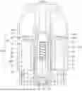
An electronic atomizing device 300 is provided in this disclosure. FIG. 1 is a structural schematic view of an electronic atomizing device according to an embodiment of the present disclosure. FIG. 2 is a lateral structural view of an atomizer of the electronic atomizing device in FIG. 1. FIG. 3 is a cross-sectional structural schematic view of the atomizer in direction III-III in FIG. 2.
The electronic atomizing device 300 may be used for atomizing the e-cigarette liquid. The electronic atomizing device 300 may include an atomizer 100 and a body assembly 200 connected to the atomizer 100. The atomizer 100 may be used for storing liquid and atomizing the liquid to form smoke that can be inhaled by a person. The liquid may be liquid matrix such as e-liquid, liquid medicine, etc. The body assembly 200 can be used to supply power to the atomizer 100 for atomizing the e-liquid and forming smoke.
In this embodiment, the case of using e-liquid as the liquids will be described in detail.
The atomizer 100 generally includes a liquid storage assembly 101 and an atomizing core assembly 102. The atomizing core assembly 102 can be arranged in the liquid storage assembly 101. The liquid storage assembly 101 can be used to store the e-liquid, the atomizing core assembly 102 can be used to atomize the e-liquid to form smoke.
Specifically, the liquid storage assembly 101 includes a housing 10, an inner wall 30 and a cigarette holder 40. The housing 10 defines a liquid storage cavity 120 and a first assembling hole 140 (as shown in FIG. 5 and FIG. 6). The first assembling hole 140 can be used to receive an end of the atomizing core assembly 102. An inner wall 30 is arranged in the liquid storage cavity 120. The cigarette holder 40 covers the housing 10. The atomizing core assembly 102 is arranged in the liquid storage cavity 120, and has a liquid inlet 52. A capillary gap 31 capable of generating capillary action is defined between the inner wall 30 and an outer wall of the atomizing core assembly 102. When liquid level of the housing 10 below a position of the liquid inlet 52, the e-liquid stored in the storage assembly 101 may be guided to the liquid inlet 52 along the capillary gap 31. The e-liquid could be guided to the liquid inlet 52 and be atomized by the atomizing core assembly 102, therefore improving a utilization rate of the e-liquid and reducing waste of the e-liquid.
In some embodiments, the atomizing core assembly 102 and the liquid storage assembly 101 can be detachably connected, such that the atomizing core assembly 102 could be replace. Referring to FIG. 3, the atomizing core assembly 102 could be pulled out from the bottom side of the atomizer 100, so as to install a new atomizing core assembly 102 into the atomizer 100. When the atomizing core assembly 102 is needed to be replaced, a user could turn the atomizer 100 upside down, and pull out the atomizing core assembly 102, such that remaining e-liquid in the liquid storage cavity 120 could be placed on a side far away from the base 20 under gravity, and the inner wall could block the e-liquid, and the e-liquid cannot move into the atomizing core assembly 102. Therefore, the e-liquid remaining in the liquid storage cavity 120 cannot leak out due to blocking of the inner wall 30, thereby avoiding the e-liquid leakage during the replacement of the atomizing core assembly 102, improving user experience.
In this embodiment, referring to FIG. 3 and FIG. 5, the housing 10 includes a cylinder 12, a cover 14 and a base 20, the cover 14 is arranged on an end of the cylinder 12, and the base 20 is arranged on the other end of the cylinder 12. The cover 14, the cylinder 12 and the base 20 cooperatively define the liquid storage cavity 120. The liquid storage cavity 120 is used for storing e-liquid. The cover 14 defines the first assembling hole 140 communicating with the liquid storage cavity 120. The first assembling hole 140 is used to receive the end of the atomizing core assembly 102.
The cover 14 defines an air hole 142, and the air hole 142 communicates with the liquid storage cavity 120. A waterproof ventilated membrane 144 covers the air hole 142 for reducing a possibility of the e-liquid in the liquid storage cavity 120 leaking from the air hole 142, which could facilitate gas exchange between the liquid storage cavity 120 and atmosphere. As a result, air pressure in the liquid storage cavity 120 can be kept consistent with the atmospheric pressure, thereby improving an ability of the atomizer 100 to withstand higher temperatures. Therefore, intracavity temperature of the liquid storage cavity 120 will not excessively fluctuate and an unbalance between the intracavity pressure and atmospheric pressure will not happen. In this way, it is possible to avoid liquid leakage caused by excessively high air pressure in the liquid storage cavity 120, which is beneficial to reduce liquid leakage of the atomizer 100.
The cover 14 further defines a liquid injection hole 145 and a mounting hole 146, the liquid injection hole 145 and the mounting hole 146 are communicated with the liquid storage cavity 120. Referring to FIG. 3 and FIG. 7, the liquid storage assembly 101 further includes a sealing plug 15. The sealing plug 15 includes a connecting cover plate 150. A first sealing column 152 and a second sealing column 154 are disposed on one side of the connecting cover plate 150. The first sealing column 152 is configured to seal off the liquid injection hole 145, and the second sealing column 154 is configured to seal off the mounting hole 146.
In some embodiments, the liquid injection hole 145 has a larger hole diameter than that of the mounting hole 146.
In this embodiment, the sealing plug 15 may be made of silicone material, plastic material, etc., and the sealing plug 15 can be configured to block and seal off the first injection hole 145 and the second injection hole 146.
During a process of injecting liquid, liquid can be injected into the liquid storage cavity 120 through the liquid injection hole 145. The mounting hole 146 can communicate with the atmosphere and the liquid storage cavity 120. In this way, during the liquid injection process, the sealing plug 15 can rotate around sealed mounting hole 146 to expose unsealed liquid injection hole 145. The liquid can be injected into the liquid storage cavity 120 through the unsealed liquid injection hole, such that the sealing plug 15 does not need to be completely separated from the cover 14 during the process of injecting liquid, which can reduce a possibility of the sealing plug 15 being lost.
Referring to FIGS. 3 and 8, a base 20 is arranged at the other end of the cylinder 12 away from the cover 14. The base 20 is connected to the cylinder 12 in a sealing manner, the base 20 defines a second assembling hole 21 corresponding to the first assembling hole 140. The second assembling hole 21 is used to receive another end of the atomizing core assembly 102.
In this embodiment, the cylinder 12 and the cover 14 are formed of a single piece, and the base 20 is detachably connected to the cylinder 12. In other embodiments of the present disclosure, the cylinder 12 and the cover 14 also can be detachably connected and/or the base 20 and the housing 10 can be formed of a single piece.
In other embodiments, the housing 10 may be in a shape of an ellipse, a sphere, a cylinder, or a diamond, or the housing 10 may have a split combination structure. The housing 10 may include a spherical housing and a bottom cover. The bottom cover and the spherical housing are connected to form the liquid storage cavity 120. In other embodiments, the housing 10 may include a rectangular housing and a top cover. The rectangular housing and the top cover are connected to form the liquid storage cavity 120.
In some embodiments, referring to FIG. 9 and FIG. 10, the atomizing core assembly 102 is installed from the first assembling hole 140 to the second assembling hole 21. A retaining ring 22 is arranged at the base 20 and around the second assembling hole 21. The inner wall 30 is located outside the retaining ring 22. The retaining ring 22 is further assembled and hermetically connected to the atomizing core assembly 102. The retaining ring 22 is configured to block the residual e-liquid in the liquid storage cavity 120, so as to reduce a possibility of the residual e-liquid entering the second assembling hole 21 and leaking out when the atomizing core assembly 102 is removed from one side of the cover 14.
The base 20 further defines an air inlet 23, and the base 20 include an electrode 24 electrically connected with the atomizing core assembly 102. The air inlet 23 is communicated with an atomizing cavity in the atomizing core assembly 102. Air entering the atomizing cavity from the air inlet 23 can carry smoke in the atomizing cavity to a human oral cavity.
In some embodiment, the atomizing core assembly 102 could be pulled out from the top side of the atomizer 100 (as shown in FIG. 10). When the atomizing core assembly 102 replacement operation is needed, the user could remove the cigarette holder 40 firstly, and then pull out the atomizing core assembly 102. In this embodiment, in order to prevent the e-liquid in the liquid storage cavity 120 from leaking out, a blocking member 27 could be arranged on the base 20 to prevent the e-liquid in the liquid storage cavity 120 from leaking out from air inlet 23 during the replacement process of the atomizing core assembly 102.
In other embodiments, referring to FIGS. 3, 5 and 8, the atomizing core assembly 102 is installed from the second assembling hole 21 to the first assembling hole 140. A retaining ring 22 is arranged on the cover 14 and around the first assembling hole 140. The inner wall 30 is located outside the retaining ring 22. The retaining ring 22 is used to block the residual e-liquid in the liquid storage cavity 120, so as to reduce a possibility of the residual e-liquid entering the first assembling hole 140 and leaking out when the atomizing core assembly 102 is removed from one side of the base 20.
The atomizing core assembly 102 defines an air inlet 23, the atomizing core assembly 102 includes an electrode 24, the air inlet 23 is communicated with an atomizing cavity of the atomizing core assembly 102, and the electrode 24 is electrically connected to an atomizing member 70 of the atomizing core assembly 102.
Referring to FIG. 3, the inner wall 30 is disposed in the liquid storage cavity 120 and a capillary gap 31 is defined between the inner wall 30 with the outer wall of the atomizing core assembly 102. The inner wall 30 is disposed corresponding to the liquid inlet 52, such that the capillary gap 31 can communicate with the liquid inlet 52. When the liquid level of the liquid storage cavity 120 is below the position of the liquid inlet 52, the liquid in the liquid storage cavity 120 can enter the liquid inlet 52 along the capillary gap 31 by the capillary action. Therefore, the residual e-liquid can flow into the liquid inlet 52 to be atomized by atomizing core assembly 102, which could improve the utilization rate of the e-liquid and reduce the waste of the e-liquid.
A gap 32 is defined between the base 20 and an end of the inner wall 30 facing the base 20. The gap 32 is in communication with the capillary gap 31. The thickness of the gap 32 is greater than or equal to 0.5 mm. The gap 32 is configured to allow the e-liquid in the liquid storage cavity 120 to pass through the capillary gap 31. The e-liquid can be guided to the liquid inlet 52 along the capillary gap 31 by the capillary action. Therefore, the e-liquid at the bottom of the liquid storage cavity 120 can flow into the liquid inlet 52 along the capillary gap 31, which could improve the utilization rate of the e-liquid and reducing the waste of the residue e-liquid. A width of the gap 32 can be greater than or equal to 0.5 mm, which could facilitate the e-liquid entering the capillary gap 31 from the gap 32.
The atomizing core assembly 102 defines the liquid inlet 52, and two ends of the atomizing core assembly 102 are respectively received the first assembling hole 140 and second assembling hole 21. Such that, the liquid inlet 52 can be located in the liquid storage cavity 120, and the e-liquid in the liquid storage cavity 120 can enters the atomizing core assembly 102 from the liquid inlet 52. The atomizing core assembly 102 also can be used to atomize the e-liquid to form smoke.
Specifically, referring to FIG. 3 or FIG. 10, the atomizing core assembly 102 includes a sleeve 50, a liquid absorbing member 60 and an atomizing member 70. The sleeve 50 may define a liquid inlet 52, the liquid absorbing member 60 can be disposed in the sleeve 50. An atomizing chamber 62 may be defined at center of the liquid absorbing member 60. The atomizing member 70 may be embedded in the atomizing chamber 62. The e-liquid can enter the sleeve 50 from the liquid inlet 52. The liquid absorbing member 60 could be a liquid absorbing cotton which could be used for absorbing the e-liquid and guiding the e-liquid to the atomizing part 70. The atomizing part 70 may be a heating wire, a ceramic atomizing core or the like which could atomize the e-liquid.
The sleeve 50 may define at least one liquid inlet 52. In this embodiment, the sleeve 50 defines a plurality of liquid inlets 52, and the plurality of liquid inlets 52 are communicated with the capillary gap 31.
The thickness of the capillary gap 31 between the inner wall 30 and the outer wall of the atomizing core assembly 102 ranges from 0.1 mm to 0.6 mm. That is, the thickness of the capillary gap 31 defined between the inner wall 30 and the outer wall of the sleeve 50 is 0.1 mm to 0.6 mm. Within this numerical range, the capillary gap 31 has a strong capillary action, which is beneficial for the e-liquid to be guided to the atomizing core assembly 102 along the capillary gap 31 for atomizing.
In some embodiments, referring to FIG. 3 and FIG. 4, the inner wall 30 is connected to the cover 14 and/or the cylinder 12.
In at least one embodiment, the inner wall 30 and the inner side wall of the cover 14 and/or the cylinder 12 are formed of a single piece, which could simplify the assembling and manufacturing process of the housing 10 and the inner wall 30.
In at least one embodiment, the inner wall 30 is detachably connected to the inner side wall of the cover 14 and/or the cylinder 12. The inner wall 30 could be plugged in the inner side wall of the cover 14 and/or the cylinder 12, or the inner wall 30 can be fixed to the inner side wall of the cover 14 and/or the cylinder 12 by a fastener. Thereby, it is convenient to disassemble the inner wall 30 form the inner side wall of the cover 14 and/or the cylinder 12, such that cleaning or replacing the inner wall 30 could be more convenient.
In other embodiments, the inner wall 30 is connected to the atomizing core assembly 102, and arranged in the liquid storage cavity 120 when the atomizing core assembly 102 are received by the first assembling hole 140 and the second assembling hole 21.
In other embodiments, the inner wall 30 and the outer wall of the sleeve 50 may be formed of a single piece. In at least one embodiment, the inner wall 30 may be detachably connected to the outer wall of the sleeve 50, for example, by snap connection or by fasteners.
In other embodiments, the inner wall 30 also could be connected to the base 20 and arranged in the liquid storage cavity 120 when the base 20 covers the cylinder 12.
In at least one embodiment, the inner wall 30 and the base 20 may be formed of a single piece. In at least one embodiment, the inner wall 30 also may be detachably connected to the base 20, for example, by plug connection or by fasteners.
In some embodiments, referring to FIG. 3 or FIG. 10, the inner wall 30 could be connected to the housing 20 or the atomizing core assembly 102. The inner wall 30 could be suspended in midair relative to the base 20, and a gap 32 could be defined between the base 20 and an end of the inner wall 30 facing the base 20.
In other embodiments, referring to FIG. 6, a portion of the end of the inner wall 30 facing the base 20 is connected to the base 20, and another portion of the end of the inner wall 30 facing the base 20 defines a notch 33 to from the gap 32.
In at least one embodiment, the inner wall 30 is connected to the housing 20 or the atomizing core assembly 102. The end of the inner wall 30 facing the base 20 abuts against the base 20 or is plugged in the base 20. The notch 33 could form the gap 32 between the inner wall 30 and the base 20. In one embodiment, the end of the inner wall 30 facing the base 20 is detachably connected to the base 20. The notch 33 could form the gap 32 between the inner wall 30 and the base 20. In another embodiment, the notch 33 may be a hole defined on the end of the inner wall 30 facing the base 20, and the notch 33 is in communication with the capillary gap 31 and form the gap 32 between the base 20 and the end of the inner wall 30 facing the base 20.
In some embodiments, the inner wall 30 has a cylindrical shape and is sleeved on an outer circumference of the atomizing core assembly 102. The inner wall 30 may be connected to the housing 10, the base 20 or the atomizing core assembly 102.
Referring to FIGS. 3, 4 and 6, the inner wall 30 has a cylindrical shape, the inner wall 30 and the housing 10 are formed of a single piece, the inner wall 30 is suspended in midair relative to the base 20, and a gap 32 is defined between the inner wall 30 and the base 20.
The inner wall 30 comprises a first wall 34 and a second wall 36 formed of a single piece. The first wall 34 is corresponded to the liquid inlet 52, the capillary gap 31 is defined between the first wall 34 and the outer wall of the atomizing core assembly 102, a non-capillary gap 35 is defined between the second wall 36 and the outer wall of the atomizing core assembly 102. The non-capillary gap 35 is communicated with the capillary gap 31. A distance between the second wall 36 and the outer wall of the atomizing core assembly 102 is greater than that between the first wall 34 and the outer wall of the atomizing core assembly 102. That is, the thickness of the non-capillary gap 35 is greater than that of the capillary gap 31.
The capillary gap 31 may have a significant capillary action, and the e-liquid below the level of the liquid inlet 52 could be guided to the liquid inlet 52 by the capillary action. The non-capillary gap 35 may have no capillary action or has an insignificant capillary action. The thickness of the non-capillary gap 35 is quite large, the e-liquid could easily enter the non-capillary gap 35. The liquid level in the non-capillary gap 35 could be consistent with liquid level of the liquid storage cavity 120, and the liquid level in the non-capillary gap 35 changes along with the changing of the liquid level of the liquid storage cavity 120. Therefore, when the liquid level of the liquid storage cavity 120 is not lower than the position of the liquid inlet 52, the e-liquid could easily enter the liquid inlet 52 through the non-capillary gap 35. When the liquid level of the liquid storage cavity 120 is lower than the position of the liquid inlet 52, the e-liquid also could easily enter the capillary gap 31 through the non-capillary gap 35. The e-liquid could be guided to the liquid inlet 52 by the capillary action of the capillary gap 31, which is beneficial to improve the efficiency of the e-liquid entering the liquid inlet 52.
In this embodiment, the inner wall 30 includes a plurality of first wall 34 and a plurality of second wall 36, the plurality of first wall 34 and the plurality of second wall 36 are alternately arranged. The first wall 34 is correspond to the liquid inlets 52 of the atomizing core assembly 102, such that the e-liquid could be guide to the liquid inlets 52 by the capillary gap 31. The second wall 36 may be corresponded to part of the sleeve 50 between adjacent liquid inlets 52, or the first wall 34 and the second wall 36 are corresponded to different liquid inlets 52, or a same liquid inlet 52 is corresponded to the adjacent first wall 34 and the adjacent second wall 36.
The plurality of first wall 34 and the plurality of second wall 36 are arranged alternately at intervals. The plurality of first wall 34 and the plurality of second wall 36 are in a cylindrical integrated structure. Furthermore, a plurality of liquid inlets 52 are evenly arranged on the outer wall of the atomizing core assembly 102. The e-liquid could be evenly guided to the plurality of liquid inlets 50 along the capillary gap 31 between the inner wall 30 and the outer wall of the atomizing core assembly 102, thereby improving liquid inletting process stability of the atomizing core assembly 102 and improving the atomizing efficiency of the atomizer 100.
Furthermore, one end of the first wall 34 facing the base 20 protrudes out of the second wall 36, and the notch 33 is defined between the second wall 36 and portions of two adjacent first walls 34 protruding out of the second wall 36. The gap 32 is defined between the first wall 34 and the base 20, the notch 33 is used to facilitate the e-liquid to enter the non-capillary gap 35 and the capillary gap 31, thereby improving the liquid inlet efficiency.
In at least one embodiment, the inner wall 30 may also include a first wall 34 and a second wall 36, and the first wall 34 and the second wall 36 are arranged in a cylindrical shape, which has been described above in detail, and will not be repeated here.
In one embodiment, the first wall 34 has a flat surface 340 facing the outer wall of the atomizing core assembly 102, the capillary gap 31 defined between the flat surface 340 and the outer wall of the atomizing core assembly 102 is non-uniform. The second wall 36 has a curved surface 360 facing the outer wall of the atomizing core assembly 102, the non-capillary gap 35 defined between the curved surface 360 and the outer wall of the atomizing core assembly 102 is uniform.
In one embodiment, the outer wall of the atomizing core assembly 102 has a cylindrical shape. In other words, the outer wall of the sleeve 50 has a cylindrical shape, and the inner wall 30 having a cylindrical shape is sleeved on the outer periphery of the sleeve 50. The side surface of the first wall 34 facing the outer wall of the sleeve 50 is a flat surface 340, the capillary gap 31 defined between the flat surface 340 and the outer wall of the sleeve 50 is non-uniform. The side surface of the second wall 36 facing the outer wall of the sleeve 50 is a curved surface 360, the non-capillary gap 35 formed between the curved surface 360 and the outer wall of the sleeve 50 is uniform.
Specifically, the first wall 34 is corresponded to the liquid inlet 52, the capillary gap 31 is defined between the flat surface 340 and the curved surface 360. The thickness of the capillary gap 31 gradually decreases from a contacting edge where the flat surface 340 is in contact with the curved surface 360 to middle of the flat surface 340. The capillary action generated by the capillary gap 31 gradually increases from the contacting edge where the flat surface 340 is in contact with the curved surface 360 to the middle of the flat surface 340, thereby the e-liquid could easily flow into the capillary gap 31 from the non-capillary gap 35, and the e-liquid at the edge of the capillary gap 31 could easily flow to the middle of the capillary gap 31. Since the middle of the capillary gap 31 has stronger adhesion to the e-liquid, the e-liquid could enter the liquid inlet 52 by the capillary action more easily.
In this embodiment, the curved surface 360 is parallel to arc surface of the sleeve 50 to form the uniform non-capillary gap 35. The non-capillary gap 35 may have no capillary action, and the liquid level in the non-capillary gap 35 is almost consistent with the liquid level of the liquid storage cavity 120. The liquid level in the non-capillary gap 35 also changes with the change of the liquid level of the liquid storage cavity 120.
In other embodiments, the inner wall 30 has a cylindrical shape. The inner wall 30 may be connected to the base 20 or the atomizing core assembly 102. The uniform capillary gap 31 may be formed between the first wall 34 and the outer wall of the atomizing core assembly 102. A uniform non-capillary gap 35 or a non-uniform non-capillary gap 35 could be defined between the second wall 36 and the outer wall of the atomizing core assembly 102.
In other embodiments, a plurality of inner walls 30 may be arranged around the atomizing core assembly 102 at intervals, and each of the inner walls 30 corresponds to a liquid inlet 52.
Referring to FIG. 10, FIG. 11 and FIG. 12, the inner walls 30 and the cover 14 could be formed of a single piece, the inner wall 30 could be suspended in midair relative to the base 20, and a gap 32 is defined between the inner walls 30 and the base 20.
A side surface of the inner wall 30 facing the atomizing core assembly 102 comprises a capillary plane 341, a first cambered surface 343 connected to one side of the capillary plane 341 and a second cambered surface 345 connected to the other side of the capillary plane 341. The first cambered surface 343 and the second cambered surface 345 are bent inward relative to the capillary plane 341. The capillary gap 31 defined between the capillary plane 341 and the outer wall of the atomizing core assembly 102 is non-uniform. The first cambered surface 343 and the second cambered surface 345 are used to reduce fluctuation interference of the e-liquid in the liquid storage cavity 120 on the capillary gap 31, thereby reducing the fluctuation of the e-liquid due to blocking of the first cambered surface 343 and the second cambered surface 345, and reducing the interference of capillary action generated by the capillary gap 31.
The outer wall of the sleeve 50 may have a cylindrical shape, and the capillary gap 31 defined between the capillary plane 341 and the arc surface of the sleeve 50 is non-uniform. The thickness of the capillary gap 31 may gradually decrease from the edge where the capillary plane 341 is in contact with the first cambered surface 343 and the second cambered surface 345 to the middle of the capillary plane 341.
In other embodiments, the plurality of inner walls 30 may be connected to the base 20 or the atomizing core assembly 102. A uniform capillary gap 31 may be defined between the inner wall 30 and the outer wall of the atomizing core assembly 102.
Further, referring to FIG. 13, a plurality of capillary grooves 37 capable of generating capillary action are defined on side surface of the inner wall 30 facing the outer wall of the atomizing core assembly 102. The capillary grooves 37 are communicated with the capillary gap 31, and the e-liquid could be guided to the liquid inlet 52 along the capillary grooves 37 and the capillary gap 31. The capillary groove 37 could further increase a contacting area between the e-liquid and the capillary gap 31, thereby the capillary gap 31 has a stronger tension and adsorption force on a surface of the smoke liquid, and generating a stronger capillary action.
The capillary groove 37 may be defined in a straight line along the inner wall 30 from the side where the base 20 is located toward the liquid inlet 52, or the capillary groove 37 is tortuously arranged along the inner wall 30 from the side where the base 20 is located toward the liquid inlet 52.
And/or, a plurality of capillary pores 38 capable of generating capillary action are defined on the inner wall 30. The capillary pores 38 may be communicated with the capillary gaps 31, and the capillary pores 38 may be configured to guide the liquid in the liquid storage cavity 120 to the liquid inlet 52.
For example, A plurality of capillary pores 38 are fully distributed inside the inner wall 30, such that the entire inner wall 30 and the capillary gap 31 both have capillary actions, thereby increasing guiding effect of capillary action and improving the liquid guiding efficiency greatly.
The plurality of capillary pores 38 may be evenly arranged inside the inner wall 30, or the plurality of capillary pores 38 may be randomly arranged inside the inner wall 30. The plurality of capillary pores 38 could be used to guide the e-liquid to the liquid inlet 52. Besides, the plurality of capillary pores 38 also could be communicated with each other. A liquid inlet port of the capillary pore 38 could be located on the side of the inner wall 30 away from the atomizing core assembly 102. The liquid inlet port of the capillary pore 38 also could be located on the side of the inner wall 30 facing the base 20. A liquid outlet port of the capillary pore 38 could be located on the side of the inner wall 30 facing the atomizing core assembly 102, and at least part of the liquid outlet port of the capillary pore 38 could be arranged corresponding to the liquid inlet port 52.
In at least one embodiment, referring to FIG. 14, the side of the inner wall 30 facing the atomizing core assembly 102 is provided with a capillary element 39, the capillary element 39 is used to guide the e-liquid located in the liquid storage cavity 120 to the inlet aperture 52.
The capillary element 39 may be made of cotton, sponge, etc., and the capillary element 39 is capable of guiding the e-liquid at a low liquid level to the liquid inlet 52 at a high position.
As shown in FIG. 14, the capillary element 39 may be filled between the inner wall 30 and the outer wall of the atomizing core assembly 102. The capillary element 39 connected to the liquid inlet 52 extends to the bottom of the liquid storage cavity 120. In another embodiment, as shown in FIG. 15, two capillary elements 39 are disposed on one edge of the inner wall 30 and respectively arranged at two sides of the capillary gap 31 to enhance the capillary action and avoid the fluctuation influence of the e-liquid on the capillary action.
Being different from the prior art, this disclosure discloses an atomizer, a liquid storage assembly of the atomizer, and an electronic atomizing device. A liquid storage cavity is defined in a housing, the housing defines a first assembling hole, a liquid inlet of the atomizing core assembly assembled in the first assembling hole is arranged in the liquid storage cavity. An inner wall is arranged in the liquid storage cavity. A capillary gap capable of generating capillary action is defined between the inner wall and an outer wall of the assembled atomizing core assembly. The inner wall corresponds to the liquid inlet. The capillary gap communicates with the liquid inlet. When liquid level in the liquid storage cavity is lower than the position of the liquid inlet, the liquid in the liquid storage cavity can enter the liquid inlet along the capillary gap by capillary action. E-liquid can enter the liquid inlet and is able to be atomized by the atomizing core assembly, thereby improving the utilization rate of the liquid in the liquid storage cavity, and reducing the residual quantity of the liquid in the liquid storage cavity, and a risk of dry burning of the atomizing core assembly also can be avoided. Therefore, in the present disclosure, the liquid below the liquid inlet of the atomizing core assembly can be guided to the liquid core assembly, the utilization rate of liquid in the liquid storage cavity can be improved, and the risk of dry burning of the atomizer can also be effectively reduced.
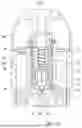
Another kind of electronic atomizing device 300 is further provided in the present disclosure. With reference to FIGS. 16-18. FIG. 16 is a structural schematic view of the electronic atomizing device 300 according to another embodiment of the present disclosure. FIG. 17 is a lateral structural schematic view of an atomizer of the electronic atomizing device 300 in FIG. 16. FIG. 18 is a first cross-sectional structural schematic view of the atomizer in direction VIII-VIII in FIG. 17.
Like the electronic atomizing device 300 illustrated in FIG. 1, the electronic atomizing device 300 may include an atomizer 100 and a body assembly 200 connected to the atomizer 100. The atomizer 100 may be used for storing atomizable material and atomizing the atomizable material to form smoke or vapor that can be inhaled by a person. The body assembly 200 may be used to supply power to the atomizer 100 for atomizing the atomizable material and forming smoke. The body assembly 300 may also be referred to as power supply. The atomizable material may be liquid matrix such as e-liquid, liquid medicine, etc.
The atomizer 100 may include housing 10. As illustrated in FIG. 19, FIG. 19 is an axial side structural schematic view of a housing 10 of the atomizer 100 in FIG. 17. Specifically, a liquid storage cavity 120 is defined in the housing 10. The housing 10 defines the first assembling hole 140. The first assembling hole 140 is used to receive the end of the atomizing core assembly 102.
The housing 10 may include an inner wall 30. The atomizer 100 may include an outer wall 54. The outer wall 54 is at least partially arranged within the inner wall 30. Namely, the outer wall 54 is at least partially arranged radially inside the inner wall 30.
In some embodiments, the inner wall 30 of the housing 10 may be eliminated, the outer wall 54 and the housing 10 are formed of a single piece, and sever as the inner wall 30 of the housing 10. In this case, the housing 10 and the outer wall 54 jointly define the liquid storage cavity 120.
The atomizing core assembly 102 is arranged within the housing 10 and at least partially arranged within the outer wall 54. Namely, the outer wall 54 at least partially surrounds the atomizing core assembly 102. As illustrated in FIG. 20, the outer wall 54 may define a first liquid inlet 541 or a plurality of first liquid inlets 541. The atomizing core assembly 102 includes a sleeve 50, and the sleeve 50 is configured to define a plurality of fluid passage holes 502. The plurality of fluid passage holes 502 may be distributed circumferentially in the sleeve 50. The sleeve 50 is at least partially arranged radially inside the outer wall 54, and configured to jointly define a capillary gap 31 with the outer wall 54. Each of the first liquid inlet 541 and the fluid passage hole 502 is connected to the capillary gap 31, and define a fluid path from any of the plurality of fluid passage holes 502 directly through the capillary gap 31 to the first liquid inlet 541. The fluid path is continuous fluid path formed by the capillary gap 31. The fluid path is from any of the fluid passage holes 502 to the first liquid inlet 541.
In the related art, when the amount of oil in the liquid storage cavity 120 drops to, for example, below half, in case the electronic atomizing device 300 is placed on its side, the first liquid inlet 541 of the atomizing core assembly 102 may be directly exposed to the air. The cavity in the liquid storage cavity 120 may easily form a pressure equilibrium with a gas channel and the external atmosphere. The oil may then continuously flow through the first liquid inlet 541 exposed to the air, resulting in oil leakage.
However, in the present disclosure, by setting a flow path formed by the capillary gap 31, surface tension and wall surface viscous resistance preventing oil flow both exit between the capillary gap 31 and the first liquid inlet 541. The surface tension and the wall viscous resistance may work together to trap the oil within the capillary gap 31, thereby preventing the first liquid inlet 541 from being directly exposed to the air. This maintains a negative pressure within the liquid storage cavity 120, creating a pressure difference between the inside and outside of the atomizing core assembly 102, so as to hinder the continuous flow of the oil into the atomizing core assembly 102 and prevent the oil leakage.
Specifically, when the electronic device 300 is placed on its side, the oil inside the atomizing core assembly 102 may flow from at least one of the fluid passage holes 502 currently at a lower position, then enter the capillary gap 31, and be guided by the capillary gap 31 to the first liquid inlet 501. The surface tension of the oil around the first liquid inlet 501 and the wall viscous resistance of the capillary gap 31 may thus prevent oil leakage through the first liquid inlet 501.
In the present embodiment, as illustrated in FIG. 19, the housing 10 includes a cylinder 12 and the inner wall 30 connected by an end plate 122. The cylinder 12, the inner wall 30 and the end plate 122 of the housing 10 together defines the liquid storage cavity 120. As illustrated in FIG. 18, the atomizer 100 includes a base 20. The base 20 is arranged on the end of the cylinder 12 opposite to the end plate 122. The cylinder 12 and the base 20 cooperatively define the liquid storage cavity 120 120. The liquid storage cavity 120 120 is used for storing or accommodating the atomizable material, such as oil. The liquid storage cavity 120 may have a shape of an annular cavity, but the shape of the liquid storage cavity 120 is not limited in the present disclosure.
The housing 10 also defines the first assembling hole 140. The first assembling hole 140 is used to receive the end of the atomizing core assembly 102.
As illustrated in FIG. 18, the base 20 is arranged at the other end of the cylinder 12 opposite to the end plate 122, and is configured to cover an end of the housing 10. The base 20 is connected to the cylinder 12 in a sealing manner. The base 20 is also configured to secure the other end of the atomizing core assembly 102.
In the present embodiment, the base 20 and the cylinder 12 may be detachably connected.
The base 20 further defines an air inlet (not illustrated). The atomizer 100 includes an electrode 24 arranged in the base 20. The electrode 24 is electrically connected with the atomizing core assembly 102. The air inlet is communicated with an atomizing cavity in the atomizing core assembly 102. Air entering the atomizing cavity from the air inlet 23 can carry smoke in the atomizing cavity to a human oral cavity.
As illustrated in FIG. 17, the electronic atomizing device 300 further includes an inhaling tube 80. The inhaling tube 80 is configured to pass through the first assembly hole 140 of the housing 10 and extend into the atomizing cavity within the atomizing core assembly 102, so as to guide the smoke in the atomizing cavity into a person's oral cavity.
Specifically, as illustrated in FIG. 18, the housing 10 further includes a liquid guiding member 61. The liquid guiding member 61 may be a liquid absorbing cotton which could be used for absorbing the oil and guides the oil to the atomizing core assembly 102. One end of the liquid guiding member 61 may extend into the liquid storage cavity 120, another end of the liquid guiding member 61 may be positioned near or abutting the first liquid inlet 541. As illustrated in FIG. 18, the other end of the first liquid-absorbing member is positioned near the first liquid inlet 541, so as to guide the oil to a cavity near the first liquid inlet 541, allowing the oil to flow into the atomizing core assembly 102 through the first liquid inlet 541. The liquid guiding member 61 60 may be supported by the base 20 or the cylinder 12, which is not restricted in the present embodiment.
As illustrated in FIGS. 20-23, FIG. 20 is a perspective view of the atomizing core assembly and the outer wall of the atomizer 100 of FIG. 17. FIG. 21 is a cross-sectional perspective view of the atomizing core assembly and the outer wall in direction X-X of FIG. 20. FIG. 22 is an axial side structural schematic view of an outer wall of FIG. 20. FIG. 23 is an axial side structural schematic view of a sleeve of the atomizing core assembly in FIG. 20
As illustrated in those Figures, the outer wall 54 has a cylindrical shape. As an example, but not a limitation, the outer wall 54 has a shape of a cylinder. The outer wall 54 defines one or a plurality of first liquid inlets 541 distributed circumferentially. The number of first liquid inlets 541 may be 2, 3, 4, 6 or 8, which is not limited here.
One end of the outer wall 54 may be fixedly connected to the base 20. Optionally, the outer wall 54 completely surrounds the atomizing core assembly 102. In this way, the oil from the liquid storage cavity 120 may enter the atomizing core assembly 102 only through the first liquid inlet 541, thereby helping to prevent oil leakage. The liquid guiding member 61 may guide the oil to the first liquid inlet 541. In this way, the first liquid inlet 541 is configured to be in fluid communication with the liquid storage cavity 120.
The atomizing core assembly 102 includes a sleeve 50, a first liquid absorbing member 62, a second liquid absorbing member 63 and the atomizing member 70.
The sleeve 50 is surrounded by the outer wall 54, and the capillary gap 31 is formed between the inner side surface of the outer wall 54 and the outer side surface of the sleeve 50 that faces each other. The thickness of the capillary gap 31 ranges from 0.1 mm to 0.6 mm. Within this numerical range, the capillary gap 31 has a strong capillary action, which is beneficial for the oil to flow along the capillary gap 31. The capillary gap 31 may be an annular gap, for example, the annular gap between the inner surface of the outer wall 54 and the outer surface of the sleeve 50.
The sleeve 50 may define a plurality of second liquid inlets 501. The plurality of second liquid inlets 501 may be arranged circumferentially in the sleeve 50. Further, the plurality of second liquid inlets 501 may be arranged evenly and circumferentially in the sleeve 50. The number of the plurality of the second liquid inlets may be 3, 4, 5, 6 or more, and is not limited here. The second liquid inlet 501 may be positioned corresponding to the first liquid inlet 541. For example, the second liquid inlet may face the first liquid inlet 541, allowing the oil from the liquid storage cavity 120 to quickly pass through the second liquid inlet 501 into the atomizing core assembly 102 when the user inhales.
In some embodiments, at least a portion of the capillary gap 31 surrounds the plurality of second liquid inlets 501, so as to form a fluid path directly through the capillary gap 31 between the plurality of second liquid inlets 501. Therefore, the plurality of second liquid inlets 501 are connect through a continuous capillary gap 31. In case that the electronic atomizing device 100 is placed on its side, a second liquid inlet 501 currently at a lower height may be immersed in oil. The oil may thus pass through this second liquid inlet 501, and enter the capillary gap 31, and finally arrive at another second liquid inlet 501 at a higher height. In this way, the second liquid inlet 501 at the higher height may be prevented from being exposed to the air, and like the reason discussed above, the surface tension and the wall viscous resistance may prevent oil leakage through the second liquid inlet 501. Further, at least a portion of the capillary gap 31 may surround the plurality of fluid passage holes 502, and form a fluid path directly through the capillary gap 31 between the plurality of second liquid inlets 501 and the plurality of fluid passage holes 502. In this way, the plurality of second liquid inlets 501 and the plurality of fluid passage holes 502 may be connected by a continuous capillary gap 31. The oil passing through the plurality of fluid passage holes 502 may be guided to the second liquid inlets 501, and helps to prevent oil leakage through the second liquid inlets 501.
The first liquid absorbing member 62 is arranged between the first liquid inlet 541 and the second liquid inlet 501. The first liquid absorbing member 62 may be a liquid absorbing cotton which could be used for absorbing and guiding the oil. The first liquid absorbing member 62 may seal at least one of the first liquid inlet 541 and the second liquid inlet 501.
In some embodiments, as specifically illustrated in FIG. 23, the sleeve 50 defines a plurality of fluid passage holes 502. The fluid passage holes 502 may include a plurality of fluid passage holes 502 arranged circumferentially in the sleeve 50. The plurality of fluid passage holes 502 may be evenly distributed circumferentially. The number of the plurality of fluid passage holes 502 may be 3, 4, 5 or more, and is not limited here.
The second liquid absorbing member 63 may be arranged within or inside the sleeve 50. The second liquid absorbing member 63 may be a liquid absorbing cotton which could be used for absorbing the oil. The second liquid absorbing member 63 may be configured to seal the plurality of second liquid inlets 501, thus may directly absorb the oil passing through the plurality of second liquid inlets 501. In some embodiment, the fluid passage hole 502 may be defined in a portion of the sleeve 50 that is distal to the second liquid absorbing member 63, thus the plurality of fluid passage holes 502 are arranged to be offset from the second liquid absorbing member 63. In this way, when the electronic atomizing device 300 is placed on its side, the oil inside the sleeve 50 may be facilitated to flow from inside the sleeve 50 to the capillary gap 31, without being directly absorbed by the second liquid absorbing member 63.
The second liquid-absorbing member 63 may, for example, be in the form of a cylinder, such as a cylindrical shape. The second liquid absorbing member 63 is configured to surround the atomizing member 70.
In some embodiments, the second liquid-absorbing member 63 defines an atomizing cavity inside itself. The atomizing cavity may, for example, be a columnar cavity. The atomizing member 70 may be arranged inside the atomizing cavity and may be in contact with the second liquid-absorbing member 63. The atomizing member 70 may be a heating wire, a ceramic atomizing core or the like which could atomize the oil. The atomizing core assembly 102 may include an atomizing member bracket 72. One end of the bracket 72 is fixed to the base 20, another end of the bracket 72 is connected to the atomizing member 70. As illustrated in FIG. 18 and FIG. 21, the bracket 72 may include two supporting arms. The atomizing member 70 is mounted on the supporting arms. As mentioned above, the atomizing member 70 is configured to connect with the electrode 24, to receive electrical energy and generate heat, thereby heating the oil in the atomizing cavity to produce smoke. The inhaling tube 80 may extend into the atomizing cavity to guide the vapor or smoke generated inside the atomizing cavity to the user's mouth.
The embodiments of the present disclosure have been described in detail above. Specific examples have been used herein to explain the principles and implementation of the present disclosure. The descriptions of the embodiments are only to help understand the method of the present disclosure and core ideas. For those skilled in the art, there will have a change in the specific embodiments and the scope of present disclosure according to the idea of the present disclosure. In summary, the content of the present specification should not be construed as limiting the present disclosure.
Claims
What is claimed is:1. An atomizer, comprising:
an outer wall, defining a first liquid inlet;
an atomizing core assembly, at least partially arranged inside the outer wall, and comprising a sleeve, the sleeve is configured to:
define a plurality of fluid passage holes;
be at least partially arranged radially inside the outer wall, and jointly define a capillary gap with the outer wall,
wherein each of the first liquid inlet and the fluid passage holes is connected to the capillary gap, defining a fluid path from any of the plurality of fluid passage holes directly through the capillary gap to the first liquid inlet.
2. The atomizer as claimed in claim 1, wherein
the plurality of fluid passage holes are arranged circumferentially in the sleeve.
3. The atomizer as claimed in claim 2, wherein
the sleeve is further configured to define a second liquid inlet,
the atomizing core assembly further comprises a first liquid absorbing member, the first liquid absorbing member is arranged between the first liquid inlet and the second liquid inlet.
4. The atomizer as claimed in claim 1, further comprising:
a housing, defining a liquid storage cavity, the liquid storage cavity being configured to accommodate atomizable material,
the first liquid inlet is configured to be in fluid communication with the liquid storage cavity.
5. The atomizer as claimed in claim 4, wherein
the outer wall and the housing are formed of a single piece, and configured to define the liquid storage cavity; or
the housing comprises an inner wall, the outer wall is at least partially arranged radially inside the inner wall.
6. The atomizer as claimed in claim 4, wherein
the housing defines a first assembling hole, the first assembling hole is configured to receive an end of the atomizing core assembly.
7. The atomizer as claimed in claim 6, further comprising:
a base, configured to cover another end of the housing,
an electrode, arranged in the base, and configured to electrically connect with the atomizing core assembly.
8. The atomizer as claimed in claim 1, wherein
the atomizing core assembly further comprises a second liquid absorbing member and an atomizing member that are arranged inside the sleeve,
the second liquid absorbing member is configured to surround the atomizing member.
9. The atomizer as claimed in claim 8, wherein
the fluid passage hole is defined in a portion of the sleeve that is distal to the second liquid absorbing member.
10. An atomizer, comprising a housing, an outer wall and an atomizing core assembly, wherein the housing is configured to define a liquid storage cavity, the liquid storage cavity is configured to accommodate atomizable material, and receive at least a portion of the atomizing core assembly;
the outer wall at least partially surrounds the atomizing core assembly;
the atomizing core assembly comprises:
a sleeve, defining a plurality of second liquid inlets distributed circumferentially, and the sleeve and the outer wall jointly defining a capillary gap,
a second liquid absorbing member, arranged inside the sleeve, the second liquid absorbing member is configured to seal the plurality of second liquid inlets,
wherein at least a portion of the capillary gap surrounds the plurality of second liquid inlets, forming a fluid path directly through the capillary gap between the plurality of second liquid inlets.
11. The atomizer as claimed in claim 10, wherein
the sleeve further defines a plurality of fluid passage holes distributed circumferentially,
at least a portion of the capillary gap surrounds the plurality of fluid passage holes, and form a fluid path directly through the capillary gap between the plurality of second liquid inlets and the plurality of fluid passage holes.
12. The atomizer as claimed in claim 10, wherein
the plurality of fluid passage holes are arranged to be offset from the second liquid absorbing member.
13. The atomizer as claimed in claim 10, wherein
the housing defines a first assembling hole, the first assembling hole is configured to receive an end of the atomizing core assembly.
14. The atomizer as claimed in claim 13, further comprising:
a base, configured to cover an end of the housing,
an electrode, arranged in the base, and configured to electrically connect with the atomizing core assembly.
15. An electronic atomizing device, comprising an atomizer and a power supply configured to supply power to the atomizer, wherein
the atomizer comprises:
an outer wall, defining a first liquid inlet;
an atomizing core assembly, at least partially arranged inside the outer wall, and comprising a sleeve, the sleeve is configured to:
define a plurality of fluid passage holes;
be at least partially arranged radially inside the outer wall, and jointly define a capillary gap with the outer wall,
wherein each of the first liquid inlet and the plurality of fluid passage holes is connected to the capillary gap, defining a fluid path from any of the plurality of fluid passage holes directly through the capillary gap to the first liquid inlet.
16. The electronic atomizing device as claimed in claim 15, wherein
the plurality of fluid passage holes are arranged circumferentially in the sleeve.
17. The electronic atomizing device as claimed in claim 16, wherein
the sleeve is further configured to define a plurality of second liquid inlets distributed circumferentially,
the atomizing core assembly further comprises a first liquid absorbing member, the first liquid absorbing member is arranged between the first liquid inlet and the second liquid inlet.
18. The electronic atomizing device as claimed in claim 15, further comprising:
a housing, defining a liquid storage cavity, the liquid storage cavity being configured to accommodate atomizable material,
the first liquid inlet is configured to be in fluid communication with the liquid storage cavity.
19. The electronic atomizing device as claimed in claim 17, wherein
the atomizing core assembly further comprises:
a second liquid absorbing member, arranged inside the sleeve, the second liquid absorbing member is configured to seal the plurality of second liquid inlets.
20. The electronic atomizing device as claimed in claim 15, wherein
at least a portion of the capillary gap surrounds the plurality of second liquid inlets, and forming a fluid path directly through the capillary gap between the plurality of second liquid inlets and the plurality of fluid passage holes.
Images & Drawings included:


Sources:
- United States Patent and Trademark Office - verify current appl. status at the USPTO↗
Similar patent applications:
- » 20210227890
METHOD AND DEVICE FOR ENERGY-SAVING CONTROL OF ELECTRONIC ATOMIZING DEVICE, AND ELECTRONIC ATOMIZING DEVICE - » 20210401056
Power supply component of electronic atomization device and electronic atomization device - » 20250134170
ELECTRONIC ATOMIZATION DEVICE AND SUPPORT FOR ELECTRONIC ATOMIZATION DEVICE - » 20220166208
Controlling device and electronic atomization device - » 20210289846
System, method, device, and electronic atomizing device for detecting nicotine content in e-liquid - » 20240349798
HEATING ATOMIZATION ASSEMBLY, HEATING ATOMIZATION DEVICE, AND ELECTRONIC ATOMIZER COMPRISING HEATING ATOMIZATION DEVICE - » 20160174076
MATCHING DEVICE AND METHOD FOR ELECTRONIC ATOMIZATION DEVICE BASED ON MOBILE TERMINAL - » 20160050196
Control device and method for electronic atomization device based on mobile terminal - » 20160269375
Authentication device and method for electronic atomization device based on mobile terminal - » 20150180488
Quantum interference device, atomic oscillator, electronic device, and moving object
Recent applications in this class:
- » 20250169543 2025-05-29
SMOKING SUBSTITUTE APPARATUS - » 20250160421 2025-05-22
ATOMIZER AND ELECTRONIC ATOMIZATION DEVICE - » 20250160420 2025-05-22
CARTRIDGE FOR USE WITH APPARATUS FOR HEATING SMOKABLE MATERIAL - » 20250160419 2025-05-22
AEROSOL PROVISION DEVICE - » 20250151804 2025-05-15
VAPORIZER DEVICES WITH BLOW DISCRIMINATION - » 20250151803 2025-05-15
AEROSOL GENERATING SYSTEM - » 20250151802 2025-05-15
ATOMIZATION BASE, ATOMIZER, AND ELECTRONIC ATOMIZATION DEVICE - » 20250151801 2025-05-15
ATOMIZER AND ELECTRONIC ATOMIZATION DEVICE - » 20250151800 2025-05-15
AEROSOL PROVISION DEVICE - » 20250151799 2025-05-15
AEROSOL PROVISION SYSTEM
Recent applications for this Assignee:
- » 20250057244 2025-02-20
ATOMIZER AND ELECTRONIC ATOMIZING DEVICE - » 20240392815 2024-11-28
ELECTRONIC CIGARETTE AND ATOMIZER THEREOF - » 20240373912 2024-11-14
ATOMIZER, HOUSING THEREFOR AND ELECTRONIC ATOMIZING APPARATUS - » 20230404151 2023-12-21
Heat-generating electronic paste composition, heat-generating electronic paste and method for preparing the same, heat-generating body of electronic cigarette and electronic cigarette - » 20230292403 2023-09-14
ATOMIZER CAPABLE OF PREVENTING LIQUID LEAKAGE CAUSED BY AIR INSIDE A LIQUID RESERVOIR AND ELECTRONIC CIGARETTE WITH THE SAME - » 20230106748 2023-04-06
Aerosol atomization device, test device, control method therefor, and control apparatus thereof - » 20230042998 2023-02-09
Electronic cigarette, atomizer and heating assembly thereof - » 20230031723 2023-02-02
Vaporization main unit and aerosol-forming device - » 20230014694 2023-01-19
Battery assembly and electronic vaporization device - » 20220409832 2022-12-29
Electronic atomization device and atomization assembly