SUPPORT STRUCTURE OF TOY FOR FIGURE PLAY
US20250144535A1
2025-05-08
18/934,662
2024-11-01
Smart Summary: A toy support structure helps hold figures in place during play. It has a base, a middle section, and a top part that supports the figure. The base has a curved surface and a flexible locking feature. A fixing part is attached to the main toy body and connects with the base. This design allows for easy attachment and removal of the figures while keeping them stable during play. 🚀 TL;DR
Abstract:
A support structure of a toy for figure play includes a supporting member and the fixing part. The supporting member includes a base end portion, a middle portion and a distal portion, and extends upward from the base end portion toward the middle portion and downward from the middle portion toward the distal end portion. The distal end portion is configured to support a supported body. The base end portion includes a contacting portion having an arcuate contacting surface and an elastic locking portion. The fixing part is fixed to a main body of the toy for figure play, and includes a contacted portion configured to contact the contacting portion and a locked portion configured to be detachably locked to the elastic locking portion.
Assignee:
- EPOCH COMPANY, LTD. 67 🇯🇵 Tokyo, Japan
Applicant:
Interested in similar patents?
Get notified when new applications in this technology area are published.
Classification:
A63H3/52 » CPC main
Dolls; Details; Accessories Dolls' houses, furniture or other equipment ; Dolls' clothing or footwear
Description
CROSS-REFERENCE TO RELATED APPLICATIONS
This application is based on and claims priority under 35 USC 119 from Japanese Patent Application No. 2023-188191 filed on Nov. 2, 2023, the contents of which are incorporated herein by reference.
TECHNICAL FIELD
The present disclosure relates to a support structure of a toy for figure play, which can be played with a figure.
BACKGROUND ART
In the related art, toys for figure play that can be played with small figures are provided. For example, JP2023-068422A discloses a toy for figure play designed in an imagination of an underwater castle. A child who is a user can imagine and have fun playing in accordance with an imagination of the toy for figure play.
SUMMARY OF INVENTION
For the toy for figure play, for example, a toy imitating a swing ride on which a figure can be placed may be provided on a supporting member extending in an arch shape from a main body of the toy for figure play. This form is enjoyable in terms of play and appearance for a child who is a user, but there is a concern that some children may have difficulty in controlling force, potentially applying force to the supporting member to damage a connecting portion between the supporting member and the main body of the toy for figure play.
An object of the present disclosure is to provide a support structure of a toy for figure play, which reduces damage to a connecting portion between a supporting member attached to a main body of the toy for figure play and the main body of the toy for figure play.
A support structure of a toy for figure play according to an aspect of the present disclosure includes: a supporting member including a base end portion, a middle portion and a distal portion, and extending upward from the base end portion toward the middle portion and downward from the middle portion toward the distal end portion, the distal end portion being configured to support a supported body, the base end portion including a contacting portion having an arcuate contacting surface and an elastic locking portion; and a fixing part fixed to a main body of the toy for figure play, the fixing part including a contacted portion configured to contact the contacting portion and a locked portion configured to be detachably locked to the elastic locking portion.
According to the above aspect, it is possible to provide a support structure of a toy for figure play, which reduces damage to a connecting portion between a supporting member attached to a main body of the toy for figure play and the main body of the toy for figure play.
BRIEF DESCRIPTION OF DRAWINGS
The present disclosure will be described in detail based on the following without being limited thereto, wherein:
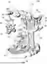
FIG. 1 is a perspective view showing an entire toy for figure play having a support structure according to an embodiment of the present disclosure;
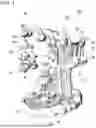
FIG. 2 is a perspective view showing a relevant part of the support structure of a toy for figure play according to the embodiment of the present disclosure;
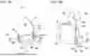
FIG. 3 is an exploded perspective view showing the relevant part of the support structure of a toy for figure play according to the embodiment of the present disclosure;
FIG. 4 is a rear view of the support structure of a toy for figure play according to the embodiment of the present disclosure;
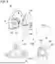
FIGS. 5A and 5B show a supporting member of the support structure of a toy for figure play according to the embodiment of the present disclosure, in which FIG. 5A is a perspective view showing a periphery of a base end portion, and FIG. 5B is a cross-sectional view taken along line Vb-Vb of FIG. 5A;
FIG. 6 is an exploded perspective view showing a rotation shaft and a periphery of a rotating body of the support structure of a toy for figure play according to the embodiment of the present disclosure; and
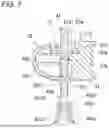
FIG. 7 is a cross-sectional view taken along line VII-VII of FIG. 2, showing the support structure of a toy for figure play according to the embodiment of the present disclosure.
DESCRIPTION OF EMBODIMENTS
An embodiment of the present disclosure will be described with reference to the drawings. FIG. 1 shows a toy 100 which serves as a toy for figure play of the present disclosure designed in an imagination of a castle floating in the sky. At a base part, a pond part 10 imitating a pond is formed on an inner side of a shape of an annular cloud. A lower surface of the pond part 10 is provided with a plurality of installation legs 110. By means of the installation legs 110, the toy 100 appears to float about 10 mm above an installation surface when installed. Note that, in the following description, a front side of the toy 100 is referred to as the front, an opposite side thereto is referred to as the rear, the pond part 10 side is referred to as the lower, an opposite side thereto is referred to as the upper, and when viewing the toy 100 from the front, a left side is referred to as the left, and a right side is referred to as the right.
A castle part 20 is provided above the pond part 10. The castle part 20 is designed in an imagination of a castle floating in clouds. The castle part 20 is provided with two elongated waterfall portions 21, which are long in the vertical direction and designed in an imagination of waterfalls flowing from the castle part 20 to the pond part 10. Note that on a rear side of the pond part 10, a tree portion 111 is provided, which is erected in a substantially plate-like shape and designed in an imagination of a tree. The castle part 20 is supported by the waterfall portions 21 and the tree portion 111. The castle part 20 is provided with a cloud-like support base part 120.
A swing ride part 40 is provided from the support base part 120 via an arcuate supporting part 30 supporting the swing ride part 40. The swing ride part 40 is provided with a rotating body 42 rotatably connected to a rotation shaft 43 imitating a sunflower. The rotating body 42 is provided with three swings 41 suspended from the rotating body 42. In addition, the pond part 10 is provided with a rotating playground equipment part 70 designed to resemble a fountain and imitating a rotating playground equipment. A boat part 80 imitating a boat is provided on a front side of the rotating playground equipment part 70. Additionally, on a right side of the castle part 20, an elevator 90 is provided with a string 92 connected via a forked branch portion 91. The elevator 90 includes a figure placement portion 93 imitating a shape of a flower, allowing for placement of a figure for play.
FIGS. 2 and 3 show a support structure 200 of the toy 100 including the swing ride part 40, the arcuate supporting part 30 supporting the swing ride part 40, and the support base part 120 to which the arcuate supporting part 30 is attached. The support base part 120 includes a fixing part 125 attached to the support base part 120, as a separate part. As shown in FIG. 3, the fixing part 125 has an internal space formed. In the internal space of the fixing part 125, a substantially long rectangular fixing hole portion 125a elongated in the left-right direction is provided, and a substantially long rectangular projection 120a protruding from a front surface of the support base part 120 is inserted and fixed therein. The support base part 120 including the fixing part 125 is formed imitating the shape of a cloud. Note that the support base part 120 may be provided with a boss, and a boss hole into which the boss fits may be provided in the internal space of the fixing part 125.
As shown in FIGS. 2 and 3, the arcuate supporting part 30 includes a base end portion 31, a distal end portion 33, and a middle portion 32, which is a connecting portion between a portion extending upward from the base end portion 31 and a portion extending downward and having the distal end portion 33. That is, the arcuate supporting part 30, which serves as a supporting member, is provided to extend upward from the base end portion 31 and extend downward via the middle portion 32. The distal end portion 33 is provided with the swing ride part 40, which serves as a supported body. Note that, in the present embodiment, the supporting member is formed in an arc shape (arcuate supporting part 30), but may be formed in another shape, such as a U-shape.
The arcuate supporting part 30 includes a supporting main body plate 30a with a plate surface facing in the front-rear direction, and supporting side edge plates 30b and 30c erected in a wall shape facing rearward along opposing edges of the supporting main body plate 30a. The supporting side edge plate 30b is provided on a radially outer side of the arcuate supporting part 30, and the supporting side edge plate 30c is provided on a radially inner side.
As shown in FIG. 4, in the internal space of the fixing part 125, a contacted plate 125b serving as a contacted portion is provided above the fixing hole portion 125a. The contacted plate 125b is arranged with a plate surface oriented in the vertical direction. The fixing hole portion 125a and the contacted plate 125b are connected to and reinforced by a vertical rib 125c with a plate surface facing in the left-right direction.
An upper surface of the fixing part 125 is provided with an opening portion 125d, which opens in a substantially long rectangular shape elongated in the left-right direction (see also FIG. 2). Both left and right end edges of the opening portion 125d are formed as locked portions 125e, which are locked on lower surfaces with locking projections 35d of an elastic locking portion 35 described below.
As shown in FIG. 4 and FIGS. 5A and 5B, an end portion on the base end portion 31 side of the arcuate supporting part 30 is provided with a contacting portion 34 having an arcuate contacting surface 34a. The contacting portion 34 is provided by being connected to the supporting main body plate 30a via a step portion 30a1 bent rearward from the supporting main body plate 30a. The contacting portion 34 includes a connecting plate 34b with a plate surface facing in the front-rear direction, and a contacting plate 34c bent rearward from a lower end of the connecting plate 34b and formed into an arc shape so as to be convex downward when viewed in the front-rear direction. A lower surface of the contacting plate 34c is the contacting surface 34a. The contacting surface 34a contacts an upper surface of the contacted plate 125b.
Note that the arcuate supporting part 30 is provided such that the supporting main body plate 30a is inclined with respect to the connecting plate 34b of the contacting portion 34. This inclination is set such that the distal end portion 33 of the arcuate supporting part 30 is positioned further forward than the base end portion 31. Therefore, the step portion 30al is substantially triangular in shape.
In addition, an end portion on the base end portion 31 side is provided with an elastic locking portion 35. The elastic locking portion 35 is formed in a hook shape when viewed in the front-rear direction so that locking projections 35d protruding outward are formed. The elastic locking portion 35 includes an elastic locking portion 35b provided continuously with the supporting side edge plate 30b and an elastic locking portion 35c provided continuously with the supporting side edge plate 30c. The elastic locking portions 35b and 35c are provided on both sides of the contacting portion 34 with slits 35a interposed, respectively. The elastic locking portions 35b and 35c are connected, on the upper side, to a rear surface side of the supporting main body plate 30a by a reinforcing plate 35e with a plate surface oriented in the vertical direction.
In a normal state, the locking projections 35d of the elastic locking portion 35 of the arcuate supporting part 30 are positioned below the locked portions 125e, and the arcuate supporting part 30 is locked and fixed to the fixing part 125. Here, when a load is applied to the arcuate supporting part 30 by pressing the arcuate supporting part 30 downward from above or pushing the same upward from below, the arcuate supporting part 30 rotates counterclockwise or clockwise when viewed from the front. At this time, the contacting surface 34a formed in the arc shape allows the counterclockwise or clockwise rotation of the arcuate supporting part 30 to be performed smoothly. Then, the elastic locking portions 35b and 35c of FIG. 4 resist the elastic force, narrowing the gaps of the slits 35a, and the elastic locking portion 35b on the left side of FIG. 4 or the elastic locking portion 35c on the right side first escapes from the locked portion 125e. Then, the elastic locking portion 35c on the right side or the elastic locking portion 35b on the left side also escapes from the locked portion 125e.
As shown in FIGS. 2 and 3, the distal end portion 33 of the arcuate supporting part 30 is provided with a shaft supporting part 36 formed in the shape of a cloud similarly to the support base part 120. As shown in FIG. 6, the shaft supporting part 36 is attached to the distal end portion 33 of the arcuate supporting part 30. Specifically, the shaft supporting part 36 is fixed to the distal end portion 33 by four bosses 33b provided at the distal end portion 33 being fitted with four boss holes (not shown) of the shaft supporting part 36. As shown in FIG. 7, the shaft supporting part 36 is fixed to the distal end portion 33, resulting in formation of a bearing part 37 by bearing surfaces 33a and 36a, which are formed as semi-cylindrical surfaces provided on the distal end portion 33 and the shaft supporting part 36, respectively.
The bearing part 37 is provided as a hole penetrating in the vertical direction. The bearing part 37 is provided with a large-diameter portion 37a on an upper side. Below the large-diameter portion 37a, a supporting surface portion 37b of a smaller diameter than the large-diameter portion 37a is provided. A step portion 37al is formed at a connecting portion between the large-diameter portion 37a and the supporting surface portion 37b. Below the supporting surface portion 37b, a shaft outer peripheral surface portion 37c having a diameter larger than that of the supporting surface portion 37b and smaller than that of the large-diameter portion 37a is provided.
The rotation shaft 43 is provided at an upper end with a flower-shaped portion 43a imitating a sunflower, and the rotation shaft 43 is formed imitating a stem of a sunflower. An upper side of the rotation shaft 43 is formed as a straight portion 43b in a straight-line shape, and a lower side is formed as a wave-shaped portion 43c curved in a wave shape. A lower end of the rotation shaft 43 is provided with an annular locking ring 43d. The straight portion 43b is provided with a disc portion 43e, which is concentric with the rotation shaft 43 and has a disc shape. In this way, the rotation shaft 43 is rotatably provided at the distal end portion 33 of the arcuate supporting part 30 and is regulated from moving at least in the downward direction.
The rotating body 42 has a locking portion 42a detachably locked to the locking ring 43d of the rotation shaft 43. The locking portion 42a is provided at an upper end of the umbrella-shaped rotating body 42. The locking portion 42a includes hook-shaped locking pieces 42al and 42a2, which are arranged facing each other in a C-ring shape. In addition, the locking pieces 42al and 42a2 are resiliently provided. At tip end portions of the locking pieces 42al and 42a2, locking projections 42a3 protruding in opposing directions are provided. The locking projection 42a3 has a tip end portion chamfered in a C-shape and a lower side formed in a step shape.
Note that, as shown in a P-portion of FIG. 6, a side surface 42a31 of the lower portion of the locking projection 42a3 is formed in a convex arc shape. This allows the rotating body 42 to smoothly rock in a direction in which the side surface 42a31 comes into sliding contact with the locking ring 43d.
When the rotating body 42 is pulled downward with a predetermined force, the locking ring 43d of the rotation shaft 43 enters between the locking projections 42a3 of the locking pieces 42al and 42a2, and escapes from the locking ring 43d while resisting the elastic force of the locking pieces 42al and 42a2. When attaching the rotating body 42, the locking ring 43d can be easily inserted between the locking pieces 42al and 42a2 because the tip end portions of the locking pieces 42al and 42a2 are chamfered into a C-shape.
In addition, the escaping force (force of pulling the rotating body 42 downward) required for causing the rotating body 42 to escape from the locking ring 43d is smaller than a releasing force required for releasing locking of the elastic locking portion 35 of the arcuate supporting part 30 and the locked portion 125e. Accordingly, even when the rotating body 42 is pulled downward, the rotating body 42 escapes from the locking ring 43d first, so a situation in which the arcuate supporting part 30 escapes from the fixing part 125 does not occur.
Note that, contrary to the present embodiment, the locking portion 42a of the rotating body 42 may be formed in an annular shape, and the locking ring 43d of the rotation shaft 43d may be formed in a C-shaped ring.
According to the embodiment of the present disclosure described above, a support structure of a toy for figure play of the following aspect can be provided.
A support structure of a toy for figure play according to a first aspect includes: a supporting member including a base end portion, a middle portion and a distal portion, and extending upward from the base end portion toward the middle portion and downward from the middle portion toward the distal end portion, the distal end portion being configured to support a supported body, the base end portion including a contacting portion having an arcuate contacting surface and an elastic locking portion; and a fixing part fixed to a main body of the toy for figure play, the fixing part including a contacted portion configured to contact the contacting portion and a locked portion configured to be detachably locked to the elastic locking portion.
With this configuration, even when a downward force is applied to the so-called arcuate supporting member, the supporting member rotates smoothly because the arcuate contacting surface contacts the contacted portion, releasing the locking between the elastic locking portion and the locked portion, allowing the supporting member to escape from the fixing part. Accordingly, damage to a connecting portion between the supporting member attached to the main body of the toy for figure play and the main body of the toy for figure play can be reduced.
In the support structure of a toy for figure play according to a second aspect, the supporting member is formed in an arc shape.
With this configuration, the supporting member with excellent aesthetic design can be provided.
In the support structure of a toy for figure play according to a third aspect, the fixing part has an opening portion, the elastic locking portion is provided on both sides of the contacting portion with a slit interposed therebetween, and the locked portion is provided at an edge portion of an opening portion.
With this configuration, the elastic force of the elastic locking portion can be easily formed as a plate spring from a structure of the component members.
In the support structure of a toy for figure play according to a fourth aspect, the supported body includes: a rotation shaft rotatably provided on the supporting member such that the rotation shaft extends in a vertical direction; and a rotating body detachably locked to the rotation shaft, and an escaping force required for causing the rotating body to escape from the rotation shaft is smaller than a releasing force required for releasing locking of the elastic locking portion and the locked portion.
With this configuration, even when the rotating body supported by the supporting member is pulled, the locking between the rotation shaft and the rotating body is released first, while the locking between the supporting member and the fixing part is maintained. Therefore, for example, when a toy such as a swing ride is used as the supported body, the locking structure of the rotating body can be easily achieved, allowing the locking release of the rotating body that is easy to pull down to be easily performed, while the release of locking of the supporting member can be reserved as a safety measure in case of an emergency.
In the support structure of a toy for figure play according to a fifth aspect, the rotating body includes a plurality of swings configured to allow one or more figures to be placed thereon.
With this configuration, it is possible to reduce breakage in a toy for figure play including a swing ride.
Although the embodiments of the present disclosure have been described, the present disclosure is not limited to the above-described embodiments and can be variously changed without departing from the scope of the present disclosure.
Claims
What is claimed is:1. A support structure of a toy for figure play, the support structure comprising:
a supporting member comprising a base end portion, a middle portion and a distal portion, and extending upward from the base end portion toward the middle portion and downward from the middle portion toward the distal end portion, the distal end portion being configured to support a supported body, the base end portion comprising a contacting portion having an arcuate contacting surface and an elastic locking portion; and
a fixing part fixed to a main body of the toy for figure play, the fixing part comprising a contacted portion configured to contact the contacting portion and a locked portion configured to be detachably locked to the elastic locking portion.
2. The support structure of a toy for figure play according to claim 1, wherein the supporting member is formed in an arc shape.
3. The support structure of a toy for figure play according to claim 1,
wherein the fixing part has an opening portion,
wherein the elastic locking portion is provided on both sides of the contacting portion with a slit interposed therebetween, and
wherein the locked portion is provided at an edge portion of an opening portion.
4. The support structure of a toy for figure play according to claim 1,
wherein the supported body comprises: a rotation shaft configured to be rotatably provided on the supporting member such that the rotation shaft extends in a vertical direction; and a rotating body detachably locked to the rotation shaft, and
wherein an escaping force required for causing the rotating body to escape from the rotation shaft is smaller than a releasing force required for releasing locking of the elastic locking portion and the locked portion.
5. The support structure of a toy for figure play according to claim 4, wherein the rotating body comprises a plurality of swings configured to allow one or more figures to be placed thereon.
Images & Drawings included:


Sources:
- United States Patent and Trademark Office - verify current appl. status at the USPTO↗
Recent applications in this class:
- » 20250161833 2025-05-22
ROBUST CHILDREN'S TOY AND SET OF ROBUST CHILDREN'S TOYS - » 20250144534 2025-05-08
TOY FOR FIGURE PLAY - » 20250083061 2025-03-13
DOLL GARMENT MANUFACTURING METHOD - » 20250083060 2025-03-13
Toy Figurine and Packaging - » 20250041744 2025-02-06
TOY HOUSE - » 20250041743 2025-02-06
COMBINED CLIMBING TOY AND TOY SLIDE FOR TOY HOUSE, AND TOY HOUSE - » 20250025799 2025-01-23
RIDE AND PLAY RIDE-ON - » 20240238686 2024-07-18
TOY FOR FIGURE PLAY - » 20240238685 2024-07-18
TOY FOR FIGURE PLAY - » 20240238684 2024-07-18
FIGURE-PLAYABLE PORTABLE TOY
Recent applications for this Assignee:
- » 20250170493 2025-05-29
DOLL AND METHOD FOR MANUFACTURING DOLL - » 20250170492 2025-05-29
DOLL HOLDER - » 20250144540 2025-05-08
FUSIBLE TOY BEAD AND METHOD FOR PRODUCING FUSIBLE TOY BEAD - » 20250144537 2025-05-08
TRAVELING TOY - » 20250144536 2025-05-08
SWINGABLE TOY - » 20250144534 2025-05-08
TOY FOR FIGURE PLAY - » 20250143345 2025-05-08
CREAMY PRODUCT, PIPING TOOL, AND METHOD FOR PRODUCING CREAMY PRODUCT - » 20250135372 2025-05-01
FOOD MODEL TOY - » 20250135371 2025-05-01
MODEL TOY AND COOKING TOY - » 20250135368 2025-05-01
LOCKING STRUCTURE