AIR-CONDITIONING APPARATUS AND INSTALLATION-POSITION DETERMINATION METHOD
US20250146689A1
2025-05-08
18/838,367
2022-04-18
Smart Summary: An air-conditioning system has an outdoor unit and several indoor units placed in different rooms. Each indoor unit has a temperature sensor that measures the air temperature in its area. A remote control is used to manage both the outdoor and indoor units. The remote control can figure out where each indoor unit is located by looking at the temperatures they detect. This helps the system work more efficiently by adjusting to the specific needs of each room. 🚀 TL;DR
Abstract:
An air-conditioning apparatus includes an outdoor unit, a plurality of indoor units installed in an air-conditioning target space, and a remote control. The plurality of indoor units include respective temperature sensors configured to detect indoor temperatures that are respective temperatures of indoor air to be sucked into the plurality of indoor units. The remote control includes a remote-control-side controller configured to control the outdoor unit and the plurality of indoor units. The remote-control-side controller is configured to determine relative installation positions of the plurality of indoor units based on the indoor temperatures detected at the plurality of indoor units.
Applicant:
Interested in similar patents?
Get notified when new applications in this technology area are published.
Classification:
F24F2110/10 » CPC further
Control inputs relating to air properties Temperature
F24F11/56 » CPC further
Control or safety arrangements characterised by user interfaces or communication Remote control
F24F11/30 » CPC main
Control or safety arrangements for purposes related to the operation of the system, e.g. for safety or monitoring
Description
TECHNICAL FIELD
The present disclosure relates to an air-conditioning apparatus provided with a plurality of indoor units and to an installation-position determination method.
BACKGROUND ART
In order to maintain an air-conditioning apparatus, it is necessary to know installation positions of an outdoor unit and an indoor unit. This means that it is necessary to determine where an outdoor unit and an indoor unit having respective specific type names and respective manufacturer's serial numbers are installed. In the past, a maintenance worker has known the installation positions of an outdoor unit and an indoor unit by referring to a working drawing of the air-conditioning apparatus.
However, in the case where a working drawing is not present, or an actual installation position is coincident with the installation position indicated by a working drawing, it is very hard to accurately know the installation position. In particular, it should be noted that in many cases, an indoor unit is fixed to a ceiling, and in order to know the installation position of the indoor unit, a maintenance worker thus needs to climb up to the ceiling and check the type name and manufacturer's serial number of the indoor unit. In view of that, in recent years, various techniques for workers to know the installation position of an indoor unit have been proposed.
For example, Patent Literature 1 discloses an air-conditioning system including a plurality of air-conditioning apparatuses, a server, and an installation-position determination device connected to the server by a network. In this air-conditioning system, the installation-position determination device obtains a captured image of a space where the plurality of air-conditioning apparatuses are installed, obtains controlled states of the plurality of air-conditioning apparatuses, and determines the installation positions of the air-conditioning apparatuses based on the obtained captured image and controlled states.
CITATION LIST
Patent Literature
Patent Literature 1: International Publication No. WO 2020/084767
Summary of Invention
Technical Problem
However, in the air-conditioning system disclosed in Patent Literature 1, it is necessary to provide an infrastructure such as the server and the network, an installation-position determination device that determines an installation position, and communication devices in order to determine the installation positions of the plurality of air-conditioning apparatuses. Inevitably, the cost required for building the infrastructure increases, and a workload on workers to prepare the communication devices also increases.
The present disclosure is applied to solve the above problem of the above related art, and relates to an air-conditioning apparatus and an installation-position determination method that can determine installation positions of a plurality of indoor units without installing additional devices and building additional infrastructure.
Solution to Problem
An air-conditioning apparatus according to one embodiment of the present disclosure includes an outdoor unit, a plurality of indoor units installed in an air-conditioning target space, and a remote control. The plurality of indoor units include respective temperature sensors configured to detect indoor temperatures that are respective temperatures of indoor air to be sucked into the plurality of indoor units. The remote control includes a remote-control-side controller configured to control the outdoor unit and the plurality of indoor units. The remote-control-side controller is configured to determine relative installation positions of the plurality of indoor units based on the indoor temperatures detected at the plurality of indoor units.
An installation-position determination method according to another embodiment of the present disclosure is an installation-position determination method of determining relative installation positions of a plurality of indoor units installed in an air-conditioning target space. The method includes determining the relative installation positions of the plurality of indoor units based on indoor temperatures detected at the plurality of indoor units.
Advantageous Effects of Invention
According to the embodiments of the present disclosure, relative installation positions of the plurality of indoor units are determined based on the indoor temperatures detected at the plurality of indoor units. It is therefore possible to determine the installation positions of the plurality of indoor units without providing additional devices and building additional infrastructure.
BRIEF DESCRIPTION OF DRAWINGS
FIG. 1 is a schematic diagram illustrating an example of the configuration of an air-conditioning apparatus according to Embodiment 1.
FIG. 2 is a schematic diagram illustrating an example of the configuration of an outdoor unit as illustrated in FIG. 1.
FIG. 3 is a schematic diagram illustrating an example of the configuration of an indoor unit as illustrated in FIG. 1.
FIG. 4 is a block diagram illustrating an example of the configuration of a remote control 30 as illustrated in FIG. 1.
FIG. 5 is a schematic diagram illustrating an example of the data structure of a signal to be transmitted and received between devices.
FIG. 6 is a schematic diagram illustrating an example of the display on the remote control 30 according to Embodiment 1.
FIG. 7 is a schematic diagram for an explanation of an effect of blowing air from a specific indoor unit on the other indoor units.
FIG. 8 is a schematic diagram for explanation of a relative positional relationship between a reference indoor unit and the other indoor units in installation-position determination processing according to Embodiment 1.
FIG. 9 is a schematic diagram for explanation of the effect of blowing air from a specific indoor unit on the other indoor units.
FIG. 10 is a schematic diagram for explanation of a relative positional relationship between the reference indoor unit and the other indoor units in the installation-position determination processing according to Embodiment 1.
FIG. 11 is a schematic diagram for explanation of the effect of blowing air from a specific indoor unit on the other indoor units.
FIG. 12 is a schematic diagram for explanation of a relative positional relationship between the reference indoor unit and the other indoor units in the installation-position determination processing according to Embodiment 1.
FIG. 13 is a schematic diagram for explanation of a method of determining installation positions of the indoor units.
FIG. 14 is a flowchart indicating an example of the flow of the installation-position determination processing by an air-conditioning apparatus 1 according to Embodiment 1.
DESCRIPTION OF EMBODIMENTS
Hereinafter, an embodiment of the present disclosure will be described with the drawings. The present disclosure is not limited to the embodiment described below. and can be variously modified without departing from the gist of the present disclosure. In each of figures in the drawings, components that are the same as or equivalent to those in a previous figure or previous figures are denoted by the same reference signs, and the same is true of the entire text of the specification. Furthermore, the level of the pressure or the temperature is not determined in relation to an absolute value, but is relatively determined based on the state, operation, and other factors of a device, an apparatus, etc.
Embodiment 1
An air-conditioning apparatus according to Embodiment 1 will be described below.
Configuration of Air-Conditioning Apparatus 1
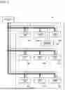
FIG. 1 is a schematic diagram illustrating an example of the configuration of an air-conditioning apparatus according to Embodiment 1. As illustrated in FIG. 1, an air-conditioning apparatus 1 includes an outdoor unit 10, a plurality of indoor units 20A to 20I, and a remote control 30. In the example illustrated in FIG. 1, the air-conditioning apparatus 1 includes one outdoor unit 10, nine indoor units 20A to 20I, and one remote control 30. It should be noted that in the following descriptions, the indoor units 20A to 20I may be individually referred simply to as “indoor unit 20” when they do not need to be distinguished from each other.
For example, the outdoor unit 10 is installed outdoors. The indoor units 20A to 20I are installed in the same air-conditioning target space to be air-conditioned. The remote control 30 is installed in, for example, the air-conditioning target space where the plurality of indoor units 20A to 20I are installed. The remote control 30 is operated, for example, by a worker who installs and maintains the air-conditioning apparatus 1 or by a user who uses the air-conditioning apparatus 1.
It should be noted that the number of outdoor units 10 and the number of remote controls 30 are not limited to the numbers indicated regarding this example, and may each be an arbitrary number. The number of indoor units 20 may be two to eight, or may be equal to 10 or more, as long as a plurality of indoor units 20 are provided.
The outdoor unit 10 and each of the indoor units 20A to 20I are connected by refrigerant pipes 2, whereby a refrigerant circuit is formed. Refrigerant, for example R32 or R410A, circulates in the refrigerant circuit.
The outdoor unit 10, a plurality of indoor units 20, and the remote control 30 are electrically connected by transmission lines 3. The transmission lines 3 are wireless, for example, but some of the transmission lines 3 may be wired lines. All the transmission lines 3 may be wired lines. A communication protocol for communication through the transmission lines 3 is not limited to a particular one. For example, a communication protocol dedicated to the air-conditioning apparatus 1 may be used, or a general-purpose communication protocol may be used.
Outdoor Unit 10
FIG. 2 is a schematic diagram illustrating an example of the configuration of the outdoor unit as illustrated in FIG. 1. As illustrated in FIG. 2, the outdoor unit 10 includes a compressor 11, a refrigerant flow switching device 12, a heat-source-side heat exchanger 13, an outdoor-side expansion valve 14, and an outdoor-side fan 15. The outdoor unit 10 further includes an outdoor-side communication module 16, an outdoor-side storage 17, and an outdoor-side controller 18. The compressor 11, the refrigerant flow switching device 12, the heat-source-side heat exchanger 13, and the outdoor-side expansion valve 14 are connected by the refrigerant pipes 2.
The compressor 11 sucks low-temperature and low-pressure refrigerant, compress the sucked refrigerant to change it into high-temperature and high-pressure refrigerant, and discharge the high-temperature and high-pressure refrigerant. The compressor 11 is, for example, an inverter compressor whose capacity is controlled by changing the operational frequency. The capacity is the volume of refrigerant to be delivered per unit time. The operational frequency of the compressor 11 is controlled by the outdoor-side controller 18.
The refrigerant flow switching device 12 is, for example, a four-way valve, and switches the flow direction of the refrigerant between plural flow directions to switch the operation between a cooling operation and a heating operation. In the cooling operation, the state of the refrigerant flow switching device 12 is switched to a state indicated by solid lines in FIG. 2, that is, a state in which a discharge side of the compressor 11 is connected to the heat-source-side heat exchanger 13. In the heating operation, the state of the refrigerant flow switching device 12 is switched to a state indicated by dotted lines in FIG. 2, that is, a state in which a suction side of the compressor 11 is connected to the heat-source-side heat exchanger 13. Switching between the above flow passages in the refrigerant flow switching device 12 is controlled by the outdoor-side controller 18.
The heat-source-side heat exchanger 13 is, for example, a fin-and-tube heat exchanger, and causes heat exchange to be performed between outdoor air and the refrigerant. In the cooling operation, the heat-source-side heat exchanger 13 operates as a condenser to transfer heat of the refrigerant to the outdoor air and condense the refrigerant. In the heating operation, the heat-source-side heat exchanger 13 operates as an evaporator to evaporate the refrigerant and cool the outdoor air by using vaporization heat generated by the evaporation.
The outdoor-side fan 15 is provided in such a manner as to face the heat-source-side heat exchanger 13. The outdoor-side fan 15 supplies outdoor air to the heat-source-side heat exchanger 13. The rotation speed of the outdoor-side fan 15 is controlled by the outdoor-side controller 18.
The outdoor-side expansion valve 14 expands the refrigerant. The outdoor-side expansion valve 14 is, for example, an electronic expansion valve whose opening degree is controllable. The opening degree of the outdoor-side expansion valve 14 is controlled by the outdoor-side controller 18.
The outdoor-side communication module 16 is an interface for communicating with the indoor units 20A to 20I and the remote control 30 through the transmission lines 3. The outdoor-side communication module 16 transmits and receives various kinds of control signals, data, and other information through the transmission lines 3. The outdoor-side communication module 16 operates as both a transmission module and a reception module to transmit a signal and receive a signal. Therefore, the outdoor-side communication module 16 is made up of a transmission device and a reception device, or is a transmitter-receiver.
The outdoor-side storage 17 is, for example, a read only memory (ROM) or a random access memory (RAM), and stores, for example, a program for controlling the outdoor unit 10. In addition, the outdoor-side storage 17 stores, for example, a control signal or data that is received through the outdoor-side communication module 16.
The outdoor-side controller 18 controls the outdoor unit 10 based on a control signal received from any of the indoor units 20A to 20I or the remote control 30 through the outdoor-side communication module 16. Specifically, the outdoor-side controller 18 controls the operational frequency of the compressor 11, the flow passage in the refrigerant flow switching device 12, the rotation speed of the outdoor-side fan 15, the opening degree of the outdoor-side expansion valve 14, etc., based on information included in the obtained control signal.
The outdoor-side controller 18 runs software on a computation device such as a microcomputer, thereby to fulfill various functions. Alternatively, the outdoor-side controller 18 is made up of hardware such as circuit devices that fulfill various functions.
Indoor Unit 20
FIG. 3 is a schematic diagram illustrating an example of the configuration of the indoor unit as illustrated in FIG. 1. As illustrated in FIG. 3, the indoor unit 20 includes a use-side heat exchanger 21, an indoor-side expansion valve 22, an indoor-side fan 23, and a temperature sensor 24. The indoor unit 20 further includes an indoor-side communication module 25, an indoor-side storage 26, and an indoor-side controller 27. The use-side heat exchanger 21 and the indoor-side expansion valve 22 are connected by the refrigerant pipe 2. It should be noted that the indoor units 20A to 20I have the same configuration, and in the following description, they may each be referred to “indoor unit 20.”
The use-side heat exchanger 21 is, for example, a fin-and-tube heat exchanger and causes heat exchange to be performed between the refrigerant and indoor air that is air in an air-conditioning target space. With this heat exchange, air for use in heating or cooling is generated and is supplied to an indoor space. In the cooling operation, the use-side heat exchanger 21 operates as an evaporator to cool the indoor air, thereby performing the cooling operation. In the heating operation, the use-side heat exchanger 31A operates as a condenser to heat the indoor air, thereby performing the heating operation.
The indoor-side fan 23 is provided in such a manner as to face the use-side heat exchanger 21. The indoor-side fan 23 supplies indoor air to the use-side heat exchanger 21. The rotation speed of the indoor-side fan 23 is controlled by the indoor-side controller 27.
The indoor-side expansion valve 22 expands the refrigerant. The indoor-side expansion valve 22 is, for example, an electronic expansion valve whose opening degree is controllable. The opening degree of the indoor-side expansion valve 22 is controlled by the indoor-side controller 27.
The temperature sensor 24 is provided at an air inlet that is provided in the indoor unit 20 and that allows indoor air to flow into the indoor unit 20. The temperature sensor 24 detects an indoor temperature that is the temperature of indoor air that is sucked from the air inlet.
The indoor-side communication module 25 is an interface through which the outdoor unit 10 and the remote control 30 communicate with each other using the transmission lines 3. The indoor-side communication module 25 transmits and receives various kinds of control signals, data, etc., through the transmission lines 3. The indoor-side communication module 25 operates as both a transmission module and a reception unit to transmit a signal and receive a signal. Therefore, the indoor-side communication module 25 is made up of a transmission module and a reception module, or is a transmitter-receiver.
The indoor-side storage 26 is, for example, a ROM or a RAM, and stores, for example, a program for controlling the indoor unit 20. The indoor-side storage 26 stores, for example, a control signal, data, etc., received through the indoor-side communication module 25. In Embodiment 1, the indoor-side storage 26 stores an indoor temperature detected by the temperature sensor 24.
The indoor-side controller 27 controls the indoor unit 20 based on a control signal received from the outdoor unit 10 or the remote control 30 through the indoor-side communication module 25. Specifically, the indoor-side controller 27 controls the rotation speed of the indoor-side fan 23, the opening degree of the indoor-side expansion valve 22, etc., based on information included in the obtained control signal.
The indoor-side controller 27 runs software on a computation device such as a microcomputer, thereby to fulfill various functions. Alternatively, the indoor-side controller 27 is hardware such as a circuit device that fulfills various functions.
Remote Control 30
FIG. 4 is a block diagram illustrating an example of the configuration of the remote control 30 as illustrated in FIG. 1. As illustrated in FIG. 4, the remote control 30 includes a display operation module 31, a remote-control-side communication module 32, a remote-control-side storage 33, and a remote-control-side controller 34.
The display operation module 31 displays various kinds of information on the air-conditioning apparatus 1 that is collected by the remote control 30. The display operation module 31 is, for example, a liquid crystal display (LCD), or an organic electro luminescence (EL) display. On the display operation module 31, for example, an image including an editing area, an input window, etc., are displayed. In Embodiment 1, in the case where the air-conditioning apparatus 1 does not operate properly. information regarding a failure is displayed on the display operation module 31.
The display operation module 31 is configured such that a touch panel including a touch sensor is stacked on a display. With this configuration, the display operation module 31 can receive an operation input from a worker. For example, the worker operates the display operation module 31, with an image including an editing area, an input window, etc., displayed on the display operation module 31, whereby various operations are performed on the air-conditioning apparatus 1.
It should be noted that in this example, the display operation module 31 is configured such that the touch panel is stacked on the display, and a display function and an operation function are provided in such a single body. However, the display operation module 31 is not limited to that of this example. For example, operation elements such as keys to be operated by the worker may be provided separately from the display operation module 31, and the display function and the operation function may be independent from each other.
The remote-control-side communication module 32 is an interface for communicating with other devices such as the outdoor unit 10 and the indoor unit 20 through the transmission lines 3. The remote-control-side communication module 32 transmits and receives various kinds of control signals, data, etc., through the transmission lines 3. The remote-control-side communication module 32 operates as both a transmission unit and a reception unit to transmit a signal and receive a signal. Therefore, the remote-control-side communication module 32 is made up of a transmission device and a reception device, or is a transmitter-receiver.
The remote-control-side storage 33 is, for example, a ROM or a RAM, and stores, for example, a program for use in control of the remote control 30. The remote-control-side storage 33 store data on details of an operation that is performed by the worker on the display operation module 31, a control signal, data, and other information received through the remote-control-side communication module 32.
The remote-control-side controller 34 controls the entire air-conditioning apparatus 1. The remote-control-side controller 34 processes the control signal, data, and other information received through the remote-control-side communication module 32, and controls operation of the air-conditioning apparatus 1 that is a target to be controlled, based on the result of the above processing.
In Embodiment 1, the remote-control-side controller 34 performs installation-position determination processing to determine an installation position of each of the indoor units 20 based on an indoor temperature that is detected at the indoor unit 20 and that is received through the remote-control-side communication module 32. The installation-position determination processing will be described later in detail.
The remote-control-side controller 34 runs software on a computation device such as a microcomputer, thereby to fulfill various functions. Alternatively, the remote-control-side controller 34 is hardware such as a circuit device that fulfills various functions.
Data Structure of Signal
Next, a data structure of a signal to be transmitted and received by each of devices through the transmission lines 3 will be described. These devices correspond to the outdoor unit 10, the indoor units 20A to 20I, and the remote control 30 that are connected by the transmission lines 3. FIG. 5 is a schematic diagram illustrating an example of the data structure of a signal to be transmitted and received between the devices. As illustrated in FIG. 5, a signal to be transmitted and received between the devices of the air-conditioning apparatus 1 according to Embodiment 1 has a header part 51, a communication command part 52, and a frame check part 53.
The header part 51 includes address information that identifies devices, such as a source address and a destination address. The destination address can indicate a specific device, and can also designate all of the devices. The header part 51 also includes information indicating the length of a telegram message of a communication command, and other information.
The communication command part 52 stores information on the communication command. The communication command part 52 includes a command for monitoring the state of a device, information for use in the control of the device, and other information. The frame check part 53 includes a code such as an error-correcting code for detecting a transmission error when a signal is transmitted or received.
Construction of Air-Conditioning Apparatus 1
Next, a construction of the air-conditioning apparatus 1 according to Embodiment 1 will be described. In Embodiment 1, the outdoor unit 10 of the air-conditioning apparatus 1 is installed mainly in an outdoor space that is a space different from an air-conditioning target space. The indoor unit 20 and the remote control 30 are installed mainly in an indoor space that is the air-conditioning target space. In particular, the indoor unit 20 is installed in a ceiling of the air-conditioning target space. After the outdoor unit 10, the indoor unit 20, and the remote control 30 are installed by a construction worker in the above manner, the outdoor unit 10 and the indoor unit 20 are connected by the refrigerant pipes 2, and the refrigerant pipes 2 are then filled with refrigerant.
Next, the outdoor unit 10, the indoor unit 20, and the remote control 30 are electrically connected by the transmission lines 3 by the worker. When the remote control 30 is operated by the worker, operation of the air-conditioning apparatus 1 is started, and it is checked whether the air-conditioning apparatus 1 operates properly or not.
At this time, the indoor-side controller 27 in the indoor unit 20 and the remote-control-side controller 34 in the remote control 30 both determine whether the air-conditioning apparatus 1 operates properly.
When determining that the air-conditioning apparatus 1 does not operate properly, the indoor-side controller 27 and the remote-control-side controller 34 each produce a command signal including a failure cause that is a cause of improper operation and an identifier that uniquely identifies a target device in which a failure occurs. Then, the indoor-side controller 27 and the remote-control-side controller 34 each transmit the produced command signal to the remote control 30 through the transmission lines 3. In this case, as an example of the identifier, a type name and a manufacturer's serial number are used. It should be noted that the identifier is not limited to that of this example, that is, any identifier can be used as long as it can uniquely identify an indoor unit 20.
FIG. 6 is a schematic diagram illustrating an example of the display on the remote control 30 according to Embodiment 1. As illustrated in FIG. 6, when the air-conditioning apparatus 1 does not properly operate, an identifier that identifies a target device in which a failure occurs and a failure cause are displayed on the display operation module 31 of the remote control 30. In this example, the type name and the manufacturer's serial number are displayed as the identifier. As the failure cause, information indicating a cause of the improper operation of the air-conditioning apparatus 1 is displayed. When the identifier and the failure cause are displayed on the display operation module 31 of the remote control 30 in the above manner, the target device is identified by the worker based on the displayed identifier, and the failure cause is eliminated.
In the case where improper operation of the air-conditioning apparatus 1 is caused by an indoor unit 20, in the past, the worker has needed to climb up to the space in the ceiling of the air-conditioning target space and confirm the type name and the manufacturer's serial number of each of the indoor units 20. Therefore, in an existing air-conditioning apparatus, it is hard to determine which of the indoor units causes a failure, on the installation site.
Therefore, the air-conditioning apparatus 1 according to Embodiment 1 performs the installation-position determination processing to determine an installation position of an indoor unit 20 that causes a failure, without the need for the worker to check the indoor units 20 individually.
Installation-Position Determination Processing
For example, in the case where a plurality of indoor units 20 are installed in a single air-conditioning target space, the temperature of air that is blown out from one of the indoor units 20 affects indoor air that is sucked into another one of the indoor units 20. Therefore, when blowing air from a certain indoor unit 20 greatly affects indoor air that is sucked into another indoor unit 20, it can be seen that the certain indoor unit 20 is installed close to the above other indoor unit 20. In contrast, when blowing air from the certain indoor unit 20 does not affect indoor air that is sucked into the other indoor unit 20, it can be seen that the certain indoor unit 20 is installed far from the other indoor unit 20.
In the installation-position determination processing by the air-conditioning apparatus 1 according to Embodiment 1, relative installation positions of the indoor units 20 with reference to one of the indoor units 20 that is selected as a reference indoor unit are determined based on the indoor temperatures detected at the indoor units 20. This installation-position determination processing is performed by the remote-control-side controller 34 of the remote control 30.
Specifically, in the installation-position determination processing, a specific indoor unit 20 is selected as a reference indoor unit from among the plurality of indoor units 20. and the indoor unit 20 selected as the reference indoor unit is operated. At this time, operation of the other indoor units 20 is stopped. This is intended to prevent air blown from the other indoor units 20 from affecting the indoor air. That is, in the installation-position determination processing, the indoor temperature detected by the temperature sensor 24 built in each of the other indoor units 20 is affected only by the blowing air from the indoor unit 20 selected as the reference indoor unit.
Case Where Indoor Unit 20A is Selected as Reference Indoor Unit
First, the following description refers to by way example the case where the indoor unit 20A is selected as a reference indoor unit. In this case, of the indoor units 20A to 20I, only the indoor unit 20A is operated, and operation of the other indoor units 20B to 20I is stopped. FIG. 7 is a schematic diagram for explanation of the effect of blowing air from a specific indoor unit on the other indoor units. FIG. 7 illustrates installation positions of the indoor units 20A to 20I in the air-conditioning target space, and the effect of blowing air such as cooled air or heated air that is blown out from the indoor unit 20A in the case where the indoor unit 20A is selected as a reference indoor unit.
For example, when only the reference indoor unit 20A is operated, the closer another one of the indoor units to the indoor unit 20A, the greater the effect of air that is blown out from the indoor unit 20A on the above other indoor unit. Thus, referring to FIG. 7, a region X1 located from the indoor unit 20A to a boundary line 40A is relatively greatly affected by the air blown from the indoor unit 20A, as compared with other regions; a region Y1 located from the boundary line 40A to a boundary line 40B is relatively less affected by the blowing air from the indoor unit 20A, as compared to other regions; and a region Z1 located from the boundary line 40B to the outside thereof is not affected by the blowing air from the indoor unit 20A.
When the indoor unit 20A is selected as a reference indoor unit as described above, in the example illustrated in FIG. 7, the indoor units 20B and 20D located in the region X1 are close to the indoor unit 20A relatively to the other indoor units 20C and 20E to 20I. Therefore, indoor air that is sucked into the indoor units 20B and 20D is greatly affected by the blowing air from the indoor unit 20A.
The indoor unit 20E located in the region Y1 is far from the indoor unit 20A relatively to the indoor units 20B and 20D, and is close to the indoor unit 20A relatively to the indoor units 20C and 20F to 20I. Therefore, indoor air that is sucked into the indoor unit 20E is slightly affected by the blowing air from the indoor unit 20A.
Furthermore, the indoor units 20C and 20F to 20I located in the region Z1 is far from the indoor unit 20A relatively to the other indoor units 20B, 20D, and 20E. Therefore, indoor air that is sucked into the indoor units 20C and 20F to 20I is not affected by the blowing air from the indoor unit 20A.
The degree of the effect of the blowing air from the reference indoor unit 20 can be determined based on indoor temperatures that are temperatures of indoor air detected at the indoor units 20. In the example illustrated in FIG. 7, the indoor units 20B and 20D installed in the region X1 are greatly affected by the blowing air from the reference indoor unit 20A. Therefore, the indoor temperature detected at each of the indoor units 20B and 20D is nearly equal to the temperature of the blowing air from the indoor unit 20A, that is, the indoor temperature detected at the indoor unit 20A, and the difference between these indoor temperatures is small.
The indoor unit 20E installed in the region Y1 is slightly affected by the blowing air from the reference indoor unit 20A. Therefore, the indoor temperature detected at the indoor unit 20E is different from the indoor temperature detected at the indoor unit 20A, and the difference between these indoor temperatures is slightly increased.
Furthermore, the indoor units 20C and 20F to 20I installed in the region Z1 are not affected by the blowing air from the reference indoor unit 20A. Therefore, the indoor temperatures detected at the indoor units 20C and 20F to 20I are greatly different from the indoor temperature detected at the indoor unit 20A, and the difference between these indoor temperatures is increased.
As described above, in the installation-position determination processing according to Embodiment 1, when a certain indoor unit 20 is selected as a reference indoor unit, it is possible to determine relative positions of the other indoor units 20 to the reference indoor unit 20 based on the differences between indoor temperatures detected at the reference indoor unit 20 and at the other indoor units 20.
FIG. 8 is a schematic diagram for explanation of a relative positional relationship between the reference indoor unit and the other indoor units in the installation-position determination processing according to Embodiment 1. FIG. 8 indicates a reference device and other devices in association with relative distances. In the case where the indoor unit 20A is selected as a reference indoor unit, when the differences between indoor temperatures detected at the reference indoor unit 20A and at the other indoor units 20B to 20I are calculated in the above manner, a relative positional relationship between the indoor unit 20A and the indoor units 20B to 20I is established as illustrated in FIG. 8.
In this example, based on the calculated temperature differences, it is determined that the indoor units 20B and 20D are each installed at a short distance from the indoor unit 20A; it is determined that the indoor unit 20E is installed at an intermediate distance from the indoor unit 20A; and it is determined that the indoor units 20C and 20F to 20I are each installed at a long distance from the indoor unit 20A.
It should be noted that each of the above terms “short distance,” “intermediate distance,” and “long distance” does not intend to indicate a specific distance. For example, the term “short distance” is used to explain that an indoor unit is close to the reference indoor unit relatively to indoor units that are each installed at the “intermediate distance” or “long distance” from the reference indoor unit; the term “intermediate distance” is used to explain that an indoor unit is far from the reference indoor unit relatively to an indoor unit that is installed at the “short distance” from the reference indoor unit and is close to the reference indoor unit relatively to an indoor unit that is installed at the “long distance” from the reference indoor unit: and the term “long distance” is used to explain that an indoor unit is far from the reference indoor unit relatively to indoor units that are each installed at the “short distance” or “intermediate distance” from the reference indoor unit.
Case Where Indoor Unit 20B is Selected as Reference Indoor Unit
The following description is made with respect to the case where the indoor unit 20B is selected as a reference indoor unit. In this case, of the indoor units 20A to 20I, only the indoor unit 20B is operated, and operation of the other indoor units 20A and 20C to 20I is stopped. FIG. 9 is a schematic diagram for explanation of the effect of air blown from a specific indoor unit on the other indoor units. FIG. 9 illustrates installation positions of the indoor units 20A to 20I in the air-conditioning target space and the effect of air that is blown from the indoor unit 20B in the case where the indoor unit 20B is selected as a reference indoor unit.
For example, in the case where only the reference indoor unit 20B is operated, the closer a region to the indoor unit 20B, the greater the effect of air blown from the indoor unit 20B to the region. Therefore, referring to FIG. 9, a region X2 located from the indoor unit 20B to a boundary line 41A is greatly affected by the blowing air from the indoor unit 20B relatively to other regions; a region Y2 located from the boundary line 41A to a boundary line 41B is slightly affected by the blowing air from the indoor unit 20B relatively to other regions; and a region Z2 located from the boundary line 41B to the outside thereof is not affected by the blowing air from the indoor unit 20B.
In the case where the indoor unit 20B is selected as a reference indoor unit as described above, in the example illustrated in FIG. 9, the indoor units 20A, 20C, and 20E installed in the region X2 are each located at a short distance from the indoor unit 20B relatively to the other indoor units 20D and 20F to 20I. Therefore, indoor air that is sucked into the indoor units 20A, 20C, and 20E is greatly affected by air blown from the indoor unit 20B. Thus, the indoor temperatures detected at the indoor units 20A, 20C, and 20E are nearly equal to the indoor temperature detected at the indoor unit 20B. The differences between those indoor temperatures are small.
The indoor units 20D and 20F installed in the region Y2 are each located at a long distance from the indoor unit 20B relatively to the indoor units 20A, 20C, and 20E, and at a short distance from the indoor unit 20B relatively to the indoor units 20G to 20I. Therefore, indoor air that is sucked into the indoor units 20D and 20F is slightly affected by the blowing air from the indoor unit 20B. Thus, the indoor temperatures detected at the indoor units 20D and 20F are different from the indoor temperature detected at the indoor unit 20B. The difference between those indoor temperatures is slightly increased.
Furthermore, the indoor units 20G to 20I installed in the region Z2 are each located at a long distance from the indoor unit 20B relatively to the other indoor units 20A and 20C to 20F. Therefore, indoor air that is sucked into the indoor units 20G to 20I is not affected by the blowing air from the indoor unit 20B. Thus, the indoor temperatures detected at the indoor units 20G to 20I are greatly different from the indoor temperature detected at the indoor unit 20B. The difference between those indoor temperatures is increased.
FIG. 10 is a schematic diagram for explanation of a relative positional relationship between the reference indoor unit and the other indoor units in the installation-position determination processing according to Embodiment 1. FIG. 10 illustrates a reference device and other devices in association with relative distances. In the case where the indoor unit 20B is selected as a reference indoor unit, when the differences between indoor temperatures detected at the reference indoor unit 20B and at the other indoor units 20A and 20C to 20I are calculated in such a manner as describe above, a relative positional relationship between the reference indoor unit 20B and the indoor units 20A and 20C to 20I is established as illustrated in FIG. 10. It should be noted that FIG. 10 additionally illustrates the relative positional relationship between the indoor unit 20A and the indoor units 20B to 20I as illustrated in FIG. 8.
In this example, based on the calculated temperature differences, it is determined that the indoor units 20A, 20C, and 20E are each installed at a short distance from the indoor unit 20B; the indoor units 20D and 20F are each installed at an intermediate distance from the indoor unit 20B; and the indoor units 20G to 20I are each installed at a long distance from the indoor unit 20B.
Case Where Indoor Unit 20D is Selected as Reference Indoor Unit
The following description is made with respect to the case where the indoor unit 20D is selected as a reference indoor unit. FIG. 11 is a schematic diagram for explanation of the effect of air blown from a specific indoor unit on the other indoor units. FIG. 11 illustrates installation positions of the indoor units 20A to 20I in the air-conditioning target space and the effect of air blown from the indoor unit 20D in the case where this indoor unit 20D is selected as a reference indoor unit.
Also in this case, the closer a region to the indoor unit 20D, the greater the effect of the blowing air from the indoor unit 20D, as in the case where the indoor unit 20A is selected as a reference indoor unit and the case where the indoor unit 20B is selected as a reference indoor unit. Therefore, referring to FIG. 11, a region X3 located from the indoor unit 20D to a boundary line 42A is greatly affected by the blowing air from the indoor unit 20D relatively to other regions; a region Y3 located from the boundary line 42A to a boundary line 42B is slightly affected by the blowing air from the indoor unit 20D relative to other regions; and a region Z3 located form the boundary line 42B to the outside thereof is not affected by the blowing air from the indoor unit 20D.
FIG. 12 is a schematic diagram for explanation of a relative positional relationship between the reference indoor unit and the other indoor units in the installation-position determination processing according to Embodiment 1. When the differences between indoor temperatures detected at the reference indoor unit 20D and at the other indoor units 20A to 20C and 20E to 20I are calculated in such a manner as describe above, a relative positional relationship between the indoor unit 20D and the indoor units 20A to 20C and 20E to 20I is established as illustrated in FIG. 12. It should be noted that FIG. 12 additionally illustrates the relative positional relationship between the indoor unit 20A and the indoor units 20B to 20I as illustrated in FIG. 8 and the relative positional relationship between the indoor unit 20B and the indoor units 20A and 20C to 20I as illustrated in FIG. 10.
In such a manner, in Embodiment 1, each of the indoor units 20 installed in the air-conditioning target space is selected as a reference indoor unit and the relative installation positions of the other indoor units 20 to the reference indoor unit are determined. Based on obtained information on the relative installation positions to the reference indoor unit, the relative installation positions of the indoor units 20 are determined.
It should be noted that preferably, the installation-position determination processing should be performed under a condition that many people or a heat source such as a PC being in operation is not present in the air-conditioning target space, or a condition that a load, for example, outdoor air such as hot air or cold air, is not applied to the processing; that is, a condition that such a load has no effect on the processing. This is intended to prevent the indoor temperatures detected at the indoor units 20 other than the reference indoor unit 20 from being changed by the effect of heat from the outside.
In general, in the indoor unit 20, a louver is provided at an air outlet from which air blows out, and the louver is capable of causing the blowing air to flow in an up-down direction. When the installation-position determination processing is performed, it is preferable that the remote-control-side controller 34 set the louver such that the louver faces upward, whereby the blowing air from the reference indoor unit 20 flows toward a ceiling to a maximum extent.
As a result, the blowing air from the reference indoor unit 20 is easily sucked into the other indoor units 20. Thus, when the installation-position determination processing is performed, it is possible to more properly determine the relative installation positions of the indoor units 20. However, even when another indoor unit 20 is selected as a reference indoor unit, it is still necessary to set the flow direction of blowing air in the same manner as described above. This is intended to prevent a relative positional relationship from being incorrectly determined in the case where another indoor unit 20 is selected as a reference indoor unit.
Furthermore, in the case where the louver provided at the indoor unit 20 can also change the flow direction of the blowing air such that the blowing air flows in a lateral direction, it is preferable to perform a swinging operation in which the louver is swung in the lateral direction during the installation-position determination processing. In this case, the remote-control-side controller 34 sets operation of the reference indoor unit 20, such that the louver of the reference indoor unit 20 is continuously swung in the lateral direction. With this operation, the blowing air from the reference indoor unit 20 is supplied to a wider area. It is therefore possible to supply the blowing air from the reference indoor unit 20 to a wider area.
In addition, when the installation-position determination processing is performed, it is preferable that the temperature of the blowing air from the reference indoor unit 20 be set in such a manner as to differ from the present indoor temperature. Specifically, in the case where, for example, the indoor temperature detected at each of the indoor units 20 in the heating operation is 22 degrees C., the reference indoor unit 20 is set to perform the heating operation at a set temperature of approximately 28 degrees C., and the installation-position determination processing is then performed. It should be noted that in the case where no person is present in the air-conditioning target space, and it is therefore unnecessary to consider comfort, the reference indoor unit 20 may perform the cooling operation at a set temperature of approximately 18 degrees C.
In this case, the remote-control-side controller 34 sets the set temperature of the reference indoor unit 20 to a temperature obtained by adding or subtracting a preset set value to or from an indoor temperature detected at the reference indoor unit 20. As a result, when the installation-position determination processing is performed, the indoor temperatures detected at the other indoor units 20 greatly vary, as compared with the case where the difference between the set temperature and the indoor temperature is small. It is possible to more reliably detect the effect of the blowing air from the reference indoor unit 20 on the other indoor units 20.
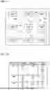
FIG. 13 is a schematic diagram for explanation of a method of determining installation positions of the indoor units. FIG. 13 shows a table that indicates the relative installation positions of the indoor units 20 other than, for example, the indoor unit 20A, 20B, or 20D in the case where the indoor unit 20A, 20B, or 20D is selected as a reference indoor unit. In the following description, in a column of the table indicated in FIG. 13, “R1”, “R2” . . . are indicated in this order from the above, and in a row of the table, “C1”, “C2” . . . are indicated in this order from the left. Specifically, it is assumed that for example, in the case where the indoor unit 20A is selected as a reference indoor unit, “R2C2” is indicated in fields indicating that the indoor units 20B and 20D are installed at a short distance from the reference indoor unit 20A.
Referring to FIG. 13, it is seem from the fields “R2C2” that the indoor units 20A, 20C, and 20E are each installed at a short distance from the indoor unit 20B. It is also seen from the fields “R2C2” that the indoor units 20A and 20E are each installed at a short distance from the indoor unit 20B. From this, it can be determined that a relative distance between the indoor unit 20A and the indoor unit 20C is longer than that between the indoor unit 20A and the indoor unit 20E, and be shorter than that between the indoor unit 20A and each of the indoor units 20F to 20I.
Similarly, it can be determined from the fields “R4C1” that the indoor unit 20G is farther from the indoor unit 20D than the indoor unit 20E, but is closer to the indoor unit 20D than the indoor units 20F. 20H, and 20I.
In such a manner, each of the indoor units 20 is selected as a reference indoor unit, and the relative installation positions of the other indoor units 20 to the reference indoor unit are determined, whereby it is possible to determine the relative installation positions of all the indoor units 20.
Even in the case where an obstacle such as a wall or a column is present between the indoor units 20 in the air-conditioning target space, the indoor units 20 are sequentially selected one by one as a reference indoor unit, whereby it is possible to correctly determine the relative installation positions of the other indoor units 20.
For example, the following description is made with respect to the case where a column is installed between the indoor unit 20A and the indoor unit 20B. In this case, when the indoor unit 20A is selected as a reference indoor unit, blowing air from the indoor unit 20A does not easily reach the indoor unit 20B because of the presence of the column. As a result, it is determined that the indoor unit 20B is relatively far from the indoor unit 20A.
In contrast, when the indoor unit 20D or 20E, which is not easily affected by the column, as compared with the indoor unit 20B, is selected as a reference indoor unit, blowing air from the indoor unit 20D or 20E easily reaches the indoor units 20A and 20B. It is therefore determined that the indoor units 20A and 20B are relatively close to the indoor unit 20D or 20E.
Therefore, based on the result obtained in the case where the indoor unit 20D or 20E is selected as a reference indoor unit, it can be assumed that an obstacle is present between the indoor units 20A and 20B, and it is therefore possible to correct the determination for the relative installation positions of the indoor units 20A and 20B.
FIG. 14 is a flowchart indicating an example of the flow of the installation-position determination processing by the air-conditioning apparatus 1 according to Embodiment 1. In step S1, the remote-control-side controller 34 in the remote control 30 produces an operation command signal including an operation command for causing an indoor unit 20, which is selected as a reference indoor unit that is a reference in the installation-position determination processing, to perform the heating operation or the cooling operation. The remote-control-side controller 34 transmits the produced operation command signal to all the indoor units 20 through the remote-control-side communication module 32.
At this time, in the header part 51 of the operation command signal, address information on the remote control 30 is set as a source address, and address information on the reference indoor unit 20 (for example, the indoor unit 20A) is set as a destination address. In the communication command part 52, a heating operation command or a cooling operation command is set for the reference indoor unit 20A.
Thus, an indoor unit 20 indicated by the address information on the destination address starts the heating operation or the cooling operation in response to the operation command set in the communication command part 52. The other indoor units 20 do not perform any operation, because they are not indicated by the address information on the destination address.
When the reference indoor unit 20 starts operation, in step S2, the remote-control-side controller 34 produces a request command signal including a request command for detecting an indoor temperature at each of the indoor units 20. The remote-control-side controller 34 transmits the produced request command signal to all the indoor units 20 through the remote-control-side communication module 32.
At this time, in the header part 51 of the request command signal, address information on the remote control 30 is set as a source address, and address information on the indoor units 20A to 20I is set as a destination address. In the communication command part 52, a request command for transmitting the indoor temperature detected by the temperature sensor 24 of each of the indoor units 20A to 20I to the remote control 30 is set.
Thus, the indoor-side controller 27 in each of the indoor units 20A to 20I indicated by the address information on the destination address detects an indoor temperature with the temperature sensor 24, in response to the request command set in the communication command part 52. Then, the indoor-side controller 27 in each of the indoor units 20A to 20I transmits the detected indoor temperature to the remote control 30 through the indoor-side communication module 25.
The remote-control-side controller 34 in the remote control 30 collects the indoor temperatures detected at the indoor units 20A to 20I through the remote-control-side communication module 32.
In step S3, the remote-control-side controller 34 in the remote control 30 determines the relative installation positions of the indoor units 20B to 20I to the reference indoor unit 20A based on the indoor temperatures collected from the indoor units 20A to 20I.
In this case, the remote-control-side controller 34 calculates the temperature differences between the indoor temperature at the reference indoor unit 20A and the indoor temperatures at the indoor units 20B to 20I. Then, the remote-control-side controller 34 compares the calculated temperature differences with a preset threshold, and determines the relative installation positions of the indoor units 20B to 20I to the reference indoor unit 20A.
More specifically, as illustrated in FIG. 7, in the case where the air-conditioning target space is divided into three regions X1, Y1, and Z1, the remote-control-side controller 34 sets a first threshold and a second threshold greater than the first threshold for the temperature difference, and stores the first and second thresholds in the remote-control-side storage 33 in advance. Then, the remote-control-side controller 34 compares the temperature difference with these two thresholds.
When the temperature difference is smaller than the first threshold, the remote-control-side controller 34 determines that an indoor unit 20 associated with the compared temperature difference is installed in the region X1. When the temperature difference is equal to or greater than the first threshold and smaller than the second threshold, the remote-control-side controller 34 determines that an indoor unit 20 associated with the compared temperature difference is installed in the region Y1. Furthermore, when the temperature difference is equal to or greater than the second threshold, the remote-control-side controller 34 determines that an indoor unit 20 associated with the compared temperature difference is installed in the region Z1.
In such a manner, the remote-control-side controller 34 determines the relative installation positions of the indoor units 20B to 20I to the indoor unit 20A. It should be noted that the number of thresholds set in advance is determined depending on the number of regions into which the air-conditioning target space is divided. For example, where the air-conditioning target space is divided into N regions (N is a natural number), (N-1) thresholds are set.
In step S4, the remote-control-side controller 34 produces a stop command signal including an operation stop command for stopping operation of each of the indoor units 20. The remote-control-side controller 34 transmits the produced stop command signal to all the indoor units 20 through the remote-control-side communication module 32.
At this time, in the header part 51 of the stop command signal, address information on the remote control 30 is set as a source address, and address information on the indoor unit 20A is set as a destination address. The operation stop command for the indoor unit 20A is set in the communication command part 52.
Thus, an indoor unit 20 indicated by the address information on the destination address stops operation in response to the operation stop command set in the communication command part 52.
In step S5, the remote-control-side controller 34 determines whether or not the processes of steps S1 to S4 are performed with reference to each of all the indoor units 20 that are sequentially selected as a reference indoor unit. When the above processes are performed with reference to each of all the indoor units 20 sequentially selected as a reference indoor unit (Yes in step S5), the processing proceeds to step S6. In step S6, the remote-control-side controller 34 displays the installation positions of the indoor units 20 on the display operation module 31.
In contrast, in step S5, when not all the indoor units 20 sequentially selected as a reference indoor unit are referred to in the above processes; that is, the above processes are not performed with reference to each of all the indoor units 20 sequentially selected as a reference indoor unit (No in step S5), the processing returns to step S1. Then, the remote-control-side controller 34 changes the reference indoor unit from the current reference indoor unit 20 to a subsequent indoor unit 20 (for example, the indoor unit 20B), and then repeats the processes of step S1 to S4.
As described above, in the air-conditioning apparatus 1 according to Embodiment 1, the remote-control-side controller 34 in the remote control 30 determines the relative installation positions of the plurality of indoor units 20 based on the indoor temperatures detected at the plurality of indoor units 20. As a result, it is possible to determine the installation positions of the plurality of indoor units 20 without providing additional devices and building additional infrastructure, and it is therefore possible to easily determine the positional relationships between the indoor units 20.
REFERENCE SIGNS LIST
-
- 1: air-conditioning apparatus, 2: refrigerant pipe, 3: transmission line, 10: outdoor unit, 11: compressor, 12: refrigerant flow switching device, 13: heat-source-side heat exchanger, 14: outdoor-side expansion valve, 15: outdoor-side fan, 16: outdoor-side communication module, 17: outdoor-side storage, 18: outdoor-side controller, 20, 20A, 20B, 20C, 20D, 20E, 20F, 20G, 20H, 20I: indoor unit, 21: use-side heat exchanger, 22: indoor-side expansion valve, 23: indoor-side fan, 24: temperature sensor, 25: indoor-side communication module, 26: indoor-side storage, 27: indoor-side controller, 30: remote control, 31: display operation module, 32: remote-control-side communication module, 33: remote-control-side storage, 34: remote-control-side controller, 40A, 40B, 41A, 41B, 42A, 42B: boundary line, 51: header part, 52: communication command part, 53: frame check part
Claims
1. An air-conditioning apparatus comprising an outdoor unit, a plurality of indoor units installed in an air-conditioning target space, and a remote control,
wherein
the plurality of indoor units include respective temperature sensors configured to detect indoor temperatures that are respective temperatures of indoor air to be sucked into the plurality of indoor units,
the remote control is configured to
control the outdoor unit and the plurality of indoor units,
store in advance a threshold for a temperature difference between an indoor temperature detected at a reference indoor unit and indoor temperatures detected at ones of the plurality of indoor units that are other than the reference indoor unit, when a specific one of the plurality of indoor units is selected as the reference indoor unit. and
compare, with the threshold, the temperature difference obtained when the reference indoor unit is operated. and determine relative installation positions of the ones of the plurality of indoor units that are other than the reference indoor unit, to the reference indoor unit.
2-3. (canceled)
4. The air-conditioning apparatus of claim 1, wherein the remote control is configured to determine that the smaller the temperature difference, the closer another one of the other indoor units to the reference indoor unit.
5. (canceled)
6. The air-conditioning apparatus of claim 1, wherein the remote control is configured to
sequentially select the plurality of indoor units one by one as the reference indoor unit, and determine the relative installation positions of the other ones of the plurality of indoor units to the reference indoor unit as which the plurality of indoor units are sequentially selected one by one, and
determine, based on the determined relative installation positions of the other ones of the plurality of indoor units, the relative installation positions of all the plurality of indoor units to the reference unit as which the plurality of indoor units are sequentially selected one by one.
7. The air-conditioning apparatus of claim 1, wherein
the reference indoor unit includes a louver configured to cause blowing air to flow in an up-down direction, and
the remote control is configured to control the reference indoor unit such that the louver faces upward, when the remote-control-side controller determines the relative installation positions of the other ones of the plurality of indoor units to the reference indoor unit.
8. The air-conditioning apparatus of claim 1, wherein
the reference indoor unit includes a louver configured to cause blowing air to flow in a lateral direction, and is capable of causing the blowing air to flow in the left-right direction, and
the remote control is configured to control the reference indoor unit such that the louver continuously operates to swing in the left-right direction, when the remote control determines the relative installation positions of the other ones of the plurality of indoor units to the reference indoor unit.
9. The air-conditioning apparatus of claim 1, wherein the remote control is configured to set a set temperature of the reference indoor unit to a temperature obtained by adding or subtracting a preset value to or from the indoor temperature detected at the reference indoor unit.
10. (canceled)
11. An air-conditioning apparatus comprising an outdoor unit, a plurality of indoor units installed in an air-conditioning target space, and a remote control,
wherein
the plurality of indoor units include respective temperature sensors configured to detect indoor temperatures that are respective temperatures of indoor air to be sucked into the plurality of indoor units,
the remote control is configured to control the outdoor unit and the plurality of indoor units,
a reference unit as which a specific one of the plurality of indoor units is selected includes a louver configured to cause blowing air to flow in an up-down direction, and
the remote control is configured to
control the reference indoor unit in such a manner as to cause the louver to face upward,
determine relative installation positions of ones of the plurality of indoor units that are other than the reference indoor unit, to the reference indoor unit, based on the indoor temperatures detected at the plurality of indoor units.
12. An air-conditioning apparatus comprising an outdoor unit, a plurality of indoor units installed in an air-conditioning target space, and a remote control,
wherein
the plurality of indoor units include respective temperature sensors configured to detect indoor temperatures that are respective temperatures of indoor air to be sucked into the plurality of indoor units,
the remote control is configured to control the outdoor unit and the plurality of indoor units,
a reference unit as which a specific one of the plurality of indoor units is selected includes a louver capable of causing blowing air to flow in a lateral direction, and
the remote control is configured to
control the reference indoor unit in such a manner as to cause the louver to continuously swing in the lateral direction,
determine relative installation positions of ones of the plurality of indoor units that are other than the reference indoor unit, to the reference indoor unit, based on the indoor temperatures detected at the plurality of indoor units.
Images & Drawings included:


Sources:
- United States Patent and Trademark Office - verify current appl. status at the USPTO↗
Recent applications in this class:
- » 20250172306 2025-05-29
Systems and Methods for Controlling Rate of Change of Air Temperature in a Building - » 20250164130 2025-05-22
LIQUID MICRONIZATION APPARATUS - » 20250155146 2025-05-15
DEVICE BASED ON ACTIVITY WITHIN PROPERTY - » 20250146688 2025-05-08
Determining HVAC Cycle Type Through Remote Web-Connected Sensor Data - » 20250116416 2025-04-10
SYSTEMS AND METHODS FOR CONTROLLING A HEATING AND AIR-CONDITIONING (HVAC) SYSTEM - » 20250102169 2025-03-27
DETECTION OF HVAC EQUIPMENT WIRED TO A THERMOSTAT - » 20250102168 2025-03-27
SYSTEM AND METHOD FOR A CONTROLLED ENVIRONMENT - » 20250075924 2025-03-06
METHOD, SYSTEM, AND APPARATUS FOR CONTROLLING A PLURALITY OF PARAMETERS IN A NON-AIR-CONDITIONED CLOSED ENVIRONMENT - » 20250067452 2025-02-27
METHODS AND SYSTEMS FOR CONTROLLING AN HVAC SYSTEM TO IDENTIFY ENERGY USAGE UNDER DIFFERENT CONTROL STRATEGIES - » 20250043979 2025-02-06
SYSTEM AND METHOD FOR MONITORING AIR QUALITY WHILE COOLING AN OUTDOOR ELECTRONIC DISPLAY ASSEMBLY