REUSABLE INSULATED ROOF SYSTEM AND METHOD
US20250154768A1
2025-05-15
18/873,941
2023-04-12
Smart Summary: A roof system is designed with a waterproof layer and a layer of insulation made from cellular glass. A special protective coating is placed on top of the insulation layer. The waterproof layer is laid loosely over this coating, allowing for easy removal later. This setup makes it simple to separate the waterproof layer from the insulation when needed. Additionally, there is a method for both installing and uninstalling the entire roof assembly efficiently. 🚀 TL;DR
Abstract:
A roof system includes a waterproofing layer and a cellular glass insulation layer. A protective coating is applied to an uppermost surface (i.e., a surface furthest from the roofing deck) of the cellular glass insulation layer. The waterproofing layer is loosely laid on the uppermost surface of the cellular glass insulation layer, such that the protective coating is positioned between the cellular glass insulation layer and the waterproofing layer. This arrangement facilitates subsequent separation (e.g., manually) of the waterproofing layer from the cellular glass insulation layer. A roof assembly is also provided which comprises a roof system and a roof deck. Also provided is a method of installing and uninstalling a roof assembly.
Inventors:
- Ellen Kuppens 4 🇧🇪 Mol, Belgium
- Marc Clynhens 1 🇧🇪 Wondelgem, Belgium
- Frank Vanhove 1 🇧🇪 Nieuwpoort, Belgium
- Sylvain Terryn 1 🇧🇪 Mouscron, Belgium
- Sven Van Caimere 1 🇧🇪 Mortsel, Belgium
Applicant:
Interested in similar patents?
Get notified when new applications in this technology area are published.
Classification:
E04D11/02 » CPC main
Roof covering, as far as not restricted to features covered by only one of groups - ; Roof covering in ways not provided for by groups - , e.g. built-up roofs, elevated load-supporting roof coverings Build-up roofs, i.e. consisting of two or more layers bonded together , at least one of the layers being of watertight composition
E04D3/351 » CPC further
Roof covering by making use of flat or curved slabs or stiff sheets; Roofing slabs or stiff sheets comprising two or more layers, e.g. for insulation at least one of the layers being composed of insulating material, e.g. fibre or foam material
E04D3/35 IPC
Roof covering by making use of flat or curved slabs or stiff sheets Roofing slabs or stiff sheets comprising two or more layers, e.g. for insulation
Description
FIELD
The present disclosure relates to a roof system which can be easily dismantled and reused. The present disclosure also relates to a method of installing and uninstalling such a roof system.
BACKGROUND
The roof is an important part of the envelope of a building. The roof primarily protects the building from the elements (e.g., precipitation). The roof should also be insulated to retain conditioned air within the building. Additionally, a roof may also perform other functions. For example, flat roofs may serve as car parking, walkways, playgrounds, terraces, and platforms for mechanical and electrical equipment.
A roof should provide reliable thermal and weatherproof protection for the entire service life of the building. Thus, insulation is also a key factor in the construction or renovation of buildings, as it can account for up to 75% of the total energy reduction potential of buildings. In this respect, the use of cellular glass insulation materials in roofing systems has increased over the years. One of the reasons for this is that these materials retain their strength and other properties, such as thermal performance and resistance to fire, over time.
While cellular glass insulation materials have proved to be a sustainable solution for roofing elements, there is an ever-growing demand for products and solutions with a reduced carbon footprint and which can contribute to a circular economy.
The present invention has been designed with these considerations in mind.
SUMMARY
In one aspect, the present disclosure relates to a roof system for a (warm) roof assembly comprising a cellular glass insulation layer and a waterproofing layer, wherein: the waterproofing layer is loosely laid above the cellular glass insulation layer; wherein the waterproofing layer remains uncoupled from the cellular glass insulation layer; wherein the cellular glass insulation layer comprises one or more layers of cellular glass insulation material; and wherein the uppermost layer of cellular glass insulation material has a protective coating on its uppermost surface, such that the protective coating forms an upper face of the cellular glass insulation layer and is positioned between the cellular glass insulation layer and the waterproofing layer.
In one aspect, the present disclosure relates to a roof assembly comprising a roof deck and a roof system as described above.
In one aspect, the present disclosure relates to a method of installing a roof assembly, comprising: (i) installing a cellular glass insulation layer to a roof deck, wherein the cellular glass insulation layer comprises one or more layers of cellular glass insulation material; (ii) coating the uppermost surface of the uppermost layer of cellular glass insulation material with a protective coating; (iii) loosely laying a waterproofing layer on the protective coating, wherein the waterproofing layer remains uncoupled from the cellular glass insulation layer; and (iv) positioning (e.g., loosely laying) roof ballast directly or indirectly abutting the upper surface of the waterproofing layer.
In one aspect, the present disclosure relates to a method of uninstalling a roof provided with a roof system as described above.
BRIEF DESCRIPTION OF THE DRAWINGS
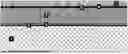
FIG. 1 shows a schematic of an exemplary roof assembly.
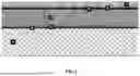
FIG. 2 shows a schematic of an exemplary roof assembly.
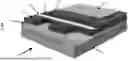
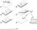
FIG. 3 shows the installation/uninstallation of an exemplary roof system.
DETAILED DESCRIPTION
Throughout this disclosure, including the appended claims, unless the context requires otherwise, the word “comprise” and “include”, and variations such as “comprises”, “comprising”, and “including” will be understood to imply the inclusion of a stated component, integer or step or group of components, integers or steps but not the exclusion of any other component, integer or step or group of components, integers or steps.
It must be noted that, as used in this disclosure and the appended claims, the singular forms “a,” “an,” and “the” include plural referents unless the context clearly dictates otherwise.
The expressions “element A is loosely laid onto/above element B” or “element A is directly laid onto/above element B” are intended to mean that there is no adhesive or any other fastening means used between the two elements, i.e., element A is placed onto element B as is, such that element A and element B are not affixed to one another. This definition also applies to the expressions “loosely laying element A onto/above element B” and “directly laying element A onto/above element B.”
The present disclosure relates to a roof system comprising a cellular glass insulation layer and a waterproofing layer.
In one aspect, the present disclosure relates to a roof system for a roof assembly comprising a cellular glass insulation layer (4,11) and a waterproofing layer (5,6; 13,14) wherein: the waterproofing layer is loosely laid above the cellular glass insulation layer; the waterproofing layer remains uncoupled from the cellular glass insulation layer; the cellular glass insulation layer comprises one or more layers of cellular glass insulation material; and the uppermost layer of cellular glass insulation material has a protective coating (12) on its uppermost surface, such that the protective coating forms an upper face of the cellular glass insulation layer and is positioned between the cellular glass insulation layer and the waterproofing layer.
In some embodiments, the roof system further includes a levelling layer (3). The levelling layer (3) can ensure the roof deck (1) has the correct slope gradient for rainwater to be carried from the roof of the building towards rainwater outlet and downpipes, guttering systems, hoppers, etc.
In some embodiments, the roof system further includes a vapor barrier (2). The vapor barrier (2) is positioned directly or indirectly between the cellular glass insulation layer (4) and the roof deck (1).
In some embodiments, the roof system further includes roof ballast (7,15) positioned directly or indirectly abutting the upper surface of the waterproofing layer.
Cellular Glass Insulation Layer
The cellular glass insulation layer comprises one or more layers of cellular glass insulation material. Cellular glass insulation material is typically provided in slabs, notably cuboid slabs. A layer of cellular glass insulation material typically includes a single layer of orthogonal and/or cuboid cellular glass insulation slabs arranged side by side. Two or more layers of cuboid cellular glass insulation slabs arranged side by side may be stacked to form the cellular glass insulation layer having more than one layer of cellular glass insulation material. The insulation material typically has a closed cell structure, i.e., the insulation material includes a number of cells comprising cell walls of insulation material and cell interiors of a different material. Typically, the cell interiors are composed of a gas, such as air, N2 and/or CO2. At the surface of a closed cell structure insulation material, the substrate may include open cells. The open cells may be formed from part of a closed cell. For example, the open cells may be created where a closed cell is formed and then the substrate is cut through the closed cell to form the surface. Cellular glass insulation materials suitable for use in the roof system of the present disclosure are available from Pittsburgh Corning Europe N. V. Such insulation materials are typically compliant with standards EN 13167, EN 14305, ASTM C552.
In some embodiments, the total thickness of the cellular glass insulation layer may be in the range of 100 to 500 mm. The thickness of the cellular glass insulation layer as used herein is the minimum distance from the uppermost to the lowermost parts of the layer. In some embodiments, the total thickness of the cellular glass insulation layer may be in the range of 250 to 400 mm. A typical thickness of cellular glass insulation material slabs is in the range of 50 to 200 mm.
In some embodiments, the cellular glass insulation layer includes from 1 to 5 cellular glass insulation material layers. In other words, the cellular glass insulation layer may be formed of a single insulation material layer. Alternatively, the cellular glass insulation layer may be formed of 2 to 5 insulation material layers stacked on top of each other. In particular embodiments, the cellular glass insulation layer includes 2 or 3 cellular glass insulation material layers. In more particular embodiments, the cellular glass insulation layer includes 2 cellular glass insulation material layers. When multiple cellular glass insulation material layers are used, any seams between adjacent cellular glass slabs in one layer are substantially covered (from above or below) by cellular glass slabs in another layer.
In some embodiments, the cellular glass insulation layer has a Reaction to Fire classification according to Standard EN 13501-1 of class A. In other words, the cellular glass insulation layer has a Reaction to Fire classification of A1 or A2 according to Standard EN 13501-1. In more particular embodiments, the cellular glass insulation layer has a Reaction to Fire classification of A1 according to Standard EN 13501-1.
Protective Coating
The protective coating is applied onto the upper surface of the cellular glass insulation layer. When the cellular glass insulation layer comprises two or more layers of cellular glass insulation material, the protective coating is applied onto the upper surface of the uppermost layer of cellular glass insulation material.
In some embodiments, the protective coating is selected from mineral protective coatings, silica-based protective coatings, and alkali metal silicate-based protective coatings. Specific examples of protective coatings suitable for applying to cellular glass insulation materials include, but are not limited to: calcium hydroxide-based coatings; examples include coatings prepared by mixing water and the product known as PC® HTAA available from Pittsburgh Corning Europe N. V.; calcium sulphate-based coatings; examples include coatings prepared by mixing water and the product known as PC® 85 available from Pittsburgh Corning Europe N. V.; modified silica-based coatings, such as two-component systems including an inorganic slurry formed from glass powders and fillers (component 1) and a modified silica dispersion (component 2); examples include coatings prepared from the product known as PC® 80M available from Pittsburgh Corning Europe N. V.; lime-based coatings and renders, such as a mixture of sands, cement and lime; examples include coatings prepared from the product known as PC® 74 A1 or A2 available from Pittsburgh Corning Europe N. V.; alkali metal silicate-based coatings, also known as alkali silicate-based coatings.
For example, the protective coating may be a coating comprising sodium silicate, potassium silicate, or a mixture thereof. In particular embodiments, the alkali metal silicate protective coating may include potassium silicate. Particular examples of suitable alkali metal silicate protective coatings are the potassium silicate coatings described in EP-A-3 626 692, the entire contents of which are incorporated herein by reference.
In some embodiments, the protective coating is applied in situ to the upper surface of cellular glass insulation layer. In other embodiments, the protective coating is pre-applied to the upper surface of cellular glass insulation layer (off site).
Application of the protective coating can be performed by any suitable method, including known methods such as spray drying or application by means of a rubber scraper or a spatula, as long as the surface cells (of the upper surface of cellular glass insulation layer) are filled.
The protective coatings described herein are typically curable at ambient temperature. It will be appreciated that depending on the time of the year (and hence on relative humidity), curing of the protective coating (once applied to the upper surface of the cellular glass insulation layer) may take a few minutes, e.g., 10 to 30 minutes, to a few hours, e.g., 2 to 5 hours, depending on the chemical composition of the coating and the reaction time of its constituents.
Waterproofing Layer
The roof system comprises a waterproofing layer which is loosely laid above the cellular glass insulation layer, which is itself coated with a protective coating. In this manner, the waterproofing layer remains uncoupled from the cellular glass insulation layer. As indicated above, the protective coating forms an upper face of the cellular glass insulation layer and is positioned between the cellular glass insulation layer and the waterproofing layer.
In some embodiments, the waterproofing layer comprises at least two layers of waterproofing material, and one of said layers is loosely laid above the cellular glass insulation layer. In such embodiments, one layer (first layer) of waterproofing material is loosely laid onto the uppermost layer of cellular glass insulation material, and the other layer (second layer) is either torched or partially or fully adhered to the first layer.
Waterproofing layers suitable for use in the roof system of the present disclosure are known. Commonly used waterproofing layers include ethylene-propylene-diene monomers (EPDM), reinforced bitumen membranes (RBMs), and single-ply membranes. Reinforced bitumen membranes RBMs may require a two-layer application. The thickness of the RBM may be in the range of 3 to 8 mm. Single-ply membranes may have a thickness in the range of 1.2 to 2 mm. A single ply-membrane may require a screed to falls. A roof screed laid to falls, also called a screed to falls, is a variable thickness screed that is laid on top of the roof deck or slab to give it the correct slope gradient for rainwater to be carried from the roof, thereby ensuring proper drainage of rainwater and preventing the accumulation of ponding water and its infiltration into the building, which enhances the durability of roof waterproofing and insulation layers.
Roof Ballast
When present, roof ballast is positioned directly or indirectly abutting the upper surface of the waterproofing layer. In other words, the roof ballast may be positioned on top of the waterproofing layer. In this way, the waterproofing layer may be weighed down and/or substantially fixed by the roof ballast.
Roof ballasts suitable for use in the roof system of the present disclosure are known. Examples of suitable roof ballasts include concrete, stone or other paving slabs, gravel ballasts, and extensive green roof. Alternatively, the roof ballast may be a raised floor access or pedestals with a floor finishing or equivalent. Such roof ballast may be used for balconies, accessible areas, pedestrian walkways, etc.
In one aspect, the present disclosure relates to a roof assembly (20) comprising a roof system as described herein and a roof deck (21), wherein the roof system is loosely laid on top of the roof deck.
In one aspect, the present disclosure relates to a roof assembly comprising a roof system as described herein, a roof deck (21), and a vapor barrier (22), wherein the vapor barrier is positioned between the lowermost layer of cellular glass insulation material and the roof deck, and wherein the cellular glass insulation layer is loosely laid onto the vapor barrier.
In some embodiments, the vapor barrier is loosely laid onto the roof deck. In some embodiments, the vapor barrier adheres to the roof deck. The function of a vapor barrier is to retard the migration of water vapor. Vapor barriers suitable for use in the roof system of the present disclosure are known. Examples of suitable vapor barriers include polyethylene, aluminum laminates, bitumen glass fleece, bitumen polyester fleece, reinforced bitumen, and reinforced bitumen with metalfoil.
In another aspect, the present disclosure provides a method of installing a roof assembly, comprising: (i) installing a cellular glass insulation layer to a roof deck, wherein the cellular glass insulation layer comprises one or more layers of cellular glass insulation material; (ii) coating the uppermost surface of the uppermost layer of cellular glass insulation material with a protective coating; (iii) loosely laying a waterproofing layer onto the protective coating, wherein the waterproofing layer comprises one or more layers of waterproofing material; and (iv) positioning roof ballast directly or indirectly abutting the upper surface of the waterproofing layer.
Step (i) comprises installing the cellular glass insulation layer, typically formed of cellular glass insulation slabs, to a roof deck. This is done by directly laying the cellular glass insulation layer onto the roof deck (sometimes referred to as the structural deck). The roof deck typically provides the platform on which the layers of the roof system are installed. Typically the roof deck is concrete slab. However, wooden and metal roof decks may be used.
FIG. 3 schematically shows a method of installing and uninstalling a roof assembly as disclosed herein. Symbol 1 shows the step of installing, in particular, loosely laying, a cellular glass insulation layer, on top of a roof deck. The step of coating the uppermost surface of the uppermost layer of cellular glass insulation material with a protective coating is not shown in FIG. 3, but a representative result thereof can be seen in FIG. 2. Symbol 2 shows the step of loosely laying a waterproofing layer onto the protective coating, resulting in the structure represented by symbol 3.
In some embodiments (not shown in FIG. 3), the installing method further comprises positioning a vapor barrier between the roof deck and the cellular glass insulation layer such that the vapor barrier is loosely laid on or adheres to the roof deck and the cellular glass insulation layer is loosely laid onto the vapor barrier.
It will be appreciated that the additional and alternative features described herein with respect to the roof system are also additional and alternative features of the method of installing the roof.
The roof system according to the present disclosure has been designed such that the cellular glass insulation material and other elements of the system can be re-used. The various elements of the system, which are loosely laid one of top of the other, can readily be dismantled and separated per product, giving access in particular to the cellular glass insulation material (typically in the form of cellular glass insulation slabs) which, even if coated, can be used as such in other insulation applications, and notably in the construction of buildings. For example, such reclaimed cellular glass insulation slabs can be re-used in a flat roof build-up construction. In addition to being a sustainable product (it is a thermal insulation product that has recycled glass and sand as base materials), the cellular glass insulation material, when used according to the systems and methods disclosed herein, can be easily recycled. In some embodiments, depending on the new application, the recycling may not require further processing of the cellular glass insulation material before it is re-used.
In another aspect, the present disclosure accordingly provides a method of uninstalling a roof assembly provided with a roof system as disclosed above, the method comprising: (i) if present, removing roof ballast; (ii) removing the waterproof layer; (iii) removing the cellular glass insulation material coated with the protective coating; and (iv) recovering any remaining uncoated cellular glass insulation slabs forming said cellular glass insulation layer.
With reference to FIG. 3, symbol 4 shows the step of removing the waterproof layer, and symbol 5 shows the step of removing the cellular glass insulation layer.
In some embodiments (not shown in FIG. 3), the uninstalling method further comprises removing the vapor barrier if present and if loosely laid onto the roof deck. This can be for example the case where the barrier is no longer needed.
As mentioned above, the coated cellular glass insulation material can be recovered and recycled in other insulation applications. This is shown in FIG. 3 (symbols {circle around (6)} and {circle around (7)}). Thus, in another aspect, the present disclosure provides the use of a coated cellular glass insulation slab recovered by the method described above as an insulation material in a roof system for a flat roof assembly. The present disclosure further provides a method of recycling coated cellular glass insulation slabs recovered by the method described above by using said recovered slabs for building a flat roof assembly.
It will be appreciated that the additional and alternative features described herein with respect to the roof system are also additional and alternative features of the method of uninstalling the roof.
While the present disclosure refers to the exemplary embodiments described above, many equivalent modifications and variations will be apparent to those skilled in the art when given this disclosure. Accordingly, the exemplary embodiments set forth above are considered to be illustrative and not limiting. Various changes to the described embodiments may be made without departing from the spirit and scope of the present disclosure.
EXAMPLES
The present disclosure is illustrated with reference to the following non-limiting Examples.
Example 1
Various coatings were prepared by homogeneously mixing starting powders with water or silica dispersion in the ratios indicated in Table 1. The coatings were applied to slabs of cellular glass to form an even coating thereon, and were then cured. The coverage, density, potlife and curing time of the coatings were determined and are reported in Table 1.
| TABLE 1 | ||||
| Starting | Ratio | Coverage | Density | Potlife/ |
| material | (w/w) | (kg/m2) | (kg/L) | Curing time |
| PC ®85 | 3:1.88 | ~1.0 | 1.32 | 20 min/1 h |
| (powder/water) | ||||
| PC ®74A1 | 3:1.88 | ~1.2 | 1.30 | 3 h/4 h |
| (powder/water) | ||||
| PC ®80M | 3:1.88 | ~1.2 | 1.46 | 3 h/4 h |
| (powder/silica | ||||
| dispersion) | ||||
It can be seen that coatings made from PC®74A1 and PC®80M showed a slightly higher coverage but a longer curing time.
Example 2
To evaluate how the coatings behave when they are subjected to condensation conditions, 200×200 mm cellular glass samples with the different coatings and with a bituminous membrane on top of each sample were tested in a climatic test chamber. The samples were subjected for one week to a temperature of +40° C. and 95% relative humidity, and for a further week to a temperature of +40° C. and 98% relative humidity. After these two weeks, no visible moisture under the bituminous membranes were observed and also no degradation or pulverization of the coatings was observed.
Example 3
Cellular glass slabs with or without coating were installed horizontally on the rack in a climatic chamber. The slabs were fully wetted, covered with a loose laid bituminous membrane, and subjected to a freeze/thaw cycling test mimicking a rapid aging test. Namely, the samples were subjected to 12 cycles −10° C./+30° C. (3 cycles/day, temperature changes 1° C./minute and keeping the cycle limits constant for at least 2 hours). At the end of the freeze/thaw cycles, a limited degradation and pulverization of the different coatings was observed, for all samples, when rubbing the surface.
The point load or crushing penetration was measured on the different coatings in accordance with EN12430. A preload of 100 N was applied on a cylindrical steel indenter (diameter of 80 mm) that was brought in contact with the samples and the deformation was at that point adjusted to zero. To measure the point load/crushing penetration, the deformation increase was measured after the force was increased to 1000 N using a displacement speed of 2 mm/min. The results are presented in Table 2.
| TABLE 2 | |||
| Thermal cycling/freeze- | Average | ||
| Coating | thaw test | deformation (mm)* | |
| PC ®85 | No | 0.20 ± 0.03 | |
| PC ®85 | 12 cy. −10/+30° C. | 0.32 ± 0.07 | |
| PC ®74A1 | No | 0.19 ± 0.03 | |
| PC ®74A1 | 12 cy. −10/+30° C. | 0.26 ± 0.04 | |
| PC ®80M | No | 0.25 ± 0.03 | |
| PC ®80M | 12 cy. −10/+30° C. | 0.33 ± 0.08 | |
| None | No | 0.37 ± 0.03 | |
| None | 12 cy. −10/+30° C. | 0.53 ± 0.14 | |
| *average of 4 samples |
All tested coatings showed low crushing penetration values. For the samples that had been subjected to freeze-thaw cycling, the values were found to be 30 to 60% higher than the reference samples, but still far below the QC-limit of 1.5 mm for uncoated cellular glass.
Example 4
The bonding strength of the different coatings was evaluated by adhering 150×150 mm steel T-irons on top of coated cellular glass slabs. Afterwards incisions were made (around the T-irons) through the coating to be able to evaluate the bond between the coatings and the cellular glass substrate. The bonding strength tests were done on initial samples (=after 1 week curing at ambient temperature) and on samples which (after a 1 week curing period) were immersed for 24 hours in tap water and then afterwards cured for 3 days at ambient temperature before the bonding strength tests were performed. All samples were tested at 23° C. on a Toniversal 20 kN equipment, with a test speed set at 10 mm/minute. The results are presented in Table 3.
| TABLE 3 | ||
| 1 week@ + 20° C. + 24 | ||
| Initial (1 week@ + 20° C.) | h immersed + 3 d cured |
| Average | Average | |||
| bond | bond | |||
| strength | strength | |||
| Coating | (kPa)* | Failure mode | (kPa)* | Failure mode |
| PC ®85 | 111 ± 13 | Cohesive | 109 ± 11 | Cohesive |
| failure in | failure in | |||
| cellular glass | cellular glass | |||
| PC ®74A1 | 124 ± 9 | Cohesive | 101 ± 8 | Cohesive |
| failure in | failure in | |||
| cellular glass | cellular glass | |||
| PC ®80M | 115 ± 19 | Cohesive | 107 ± 12 | Cohesive |
| failure in | failure in | |||
| cellular glass | cellular glass | |||
| *average of 4 samples |
No significant differences were observed in the bonding strength since all failures were found cohesively in cellular glass.
Example 5
200×200 mm samples were cut from coated slabs as prepared in example 1 and then tested (at +23° C.) for short term water absorption by partial immersion in accordance with ISO 29767 (EN1609), method B. The initial mass m0 was determined and the test sample was then placed in a water bath in such position that it was partially immersed in water with the bottom face of the test sample 10±2 mm below the water level. After 10 s, the test sample was removed holding it horizontally and placed within 5 s in a plastic tray of known mass. This gave the initial water uptake m1. The test sample was placed again in the water bath, partially immersed (10±2 mm) under conditions such that the water level remained constant during the test. After 24 hours the test sample was removed and the mass m24 was determined, allowing the short term water absorption value to be calculated. The results are presented in Table 4.
| TABLE 4 | ||
| Water absorption | ||
| Coating | (kg/m2) | |
| PC ®74A1 | 0.42 | |
| PC ®80M | 0.41 | |
All coatings showed low water absorption value (<0.5 kg/m2). After a three weeks exposure to the partial water absorption a limited degradation and pulverization of the different coatings was observed for all samples (when rubbing the surface).
Claims
1. A roof system for a roof assembly, the roof system comprising:
a cellular glass insulation layer; and
a waterproofing layer,
wherein the waterproofing layer is loosely laid above the cellular glass insulation layer;
wherein the cellular glass insulation layer comprises one or more layers of cellular glass insulation material; and
wherein the uppermost layer of cellular glass insulation material has a protective coating on its uppermost surface, such that the protective coating forms an upper face of the cellular glass insulation layer and is positioned between the cellular glass insulation layer and the waterproofing layer.
2. The roof system of claim 1, wherein the waterproofing layer comprises at least two layers of waterproofing material, and
wherein one of said layers is loosely laid above the cellular glass insulation layer.
3. The roof system of claim 1, wherein the protective coating is selected from mineral protective coatings, silica-based protective coatings, and alkali metal silicate-based protective coatings.
4. The roof system of claim 1, wherein the protective coating is selected from calcium hydroxide-based coatings, calcium sulphate-based coatings, modified silica-based coatings, lime-based coatings and renders, and alkali metal silicate-based coatings.
5. The roof system of claim 1, wherein the cellular glass insulation layer is formed of a plurality of cellular glass insulation slabs.
6. The roof system of claim 1, which further comprises roof ballast positioned directly or indirectly abutting the upper surface of the waterproofing layer.
7. A roof assembly comprising a roof system and a roof deck, wherein the roof system is loosely laid on top of the roof deck, and wherein the roof system comprises:
a cellular glass insulation layer; and
a waterproofing layer,
wherein the waterproofing layer is loosely laid above the cellular glass insulation layer;
wherein the cellular glass insulation layer comprises one or more layers of cellular glass insulation material; and
wherein the uppermost layer of cellular glass insulation material has a protective coating on its uppermost surface, such that the protective coating forms an upper face of the cellular glass insulation layer and is positioned between the cellular glass insulation layer and the waterproofing layer.
8. A roof assembly comprising:
a roof system comprising:
a cellular glass insulation layer; and
a waterproofing layer,
wherein the waterproofing layer is loosely laid above the cellular glass insulation layer;
wherein the cellular glass insulation layer comprises one or more layers of cellular glass insulation material; and
wherein the uppermost layer of cellular glass insulation material has a protective coating on its uppermost surface, such that the protective coating forms an upper face of the cellular glass insulation layer and is positioned between the cellular glass insulation layer and the waterproofing layer;
a roof deck; and
a vapor barrier,
wherein the vapor barrier is positioned between the lowermost layer of cellular glass insulation material and the roof deck, and
wherein the cellular glass insulation layer is loosely laid onto the vapor barrier.
9. The roof assembly of claim 8, wherein the vapor barrier is loosely laid onto the roof deck.
10. A method of installing a roof assembly, the method comprising:
(i) installing a cellular glass insulation layer to a roof deck, wherein the cellular glass insulation layer comprises one or more layers of cellular glass insulation material;
(ii) coating the uppermost surface of the uppermost layer of cellular glass insulation material with a protective coating;
(iii) loosely laying a waterproofing layer onto the protective coating, wherein the waterproofing layer comprises one or more layers of waterproofing material; and
(iv) positioning roof ballast directly or indirectly abutting the upper surface of the waterproofing layer.
11. The method of claim 10, wherein the cellular glass insulation layer is formed of cellular glass insulation slabs.
12. The method of claim 10, which further comprises positioning a vapor barrier between the roof deck and the cellular glass insulation layer such that the vapor barrier is loosely laid onto or adheres to the roof deck and the cellular glass insulation layer is loosely laid on the vapor barrier.
13. The method of any of claim 10, wherein the protective coating is selected from mineral protective coatings, silica-based protective coatings, and alkali metal silicate-based protective coatings.
14. The method of any of claim 10, wherein the protective coating is selected from calcium hydroxide-based coatings, calcium sulphate-based coatings, modified silica-based coatings, lime-based coatings and renders, and alkali metal silicate-based coatings.
15. A method of uninstalling a roof assembly comprising a roof system and a roof deck, wherein the roof system is loosely laid on top of the roof deck, and wherein the roof system comprises: a cellular glass insulation layer;
and a waterproofing layer, wherein the waterproofing layer is loosely laid above the cellular glass insulation layer; wherein the cellular glass insulation layer comprises one or more layers of cellular glass insulation material; and wherein the uppermost layer of cellular glass insulation material has a protective coating on its uppermost surface, such that the protective coating forms an upper face of the cellular glass insulation layer and is positioned between the cellular glass insulation layer and the waterproofing layer, the method comprising:
(i) if present, removing a roof ballast;
(ii) removing the waterproofing layer;
(iii) removing the cellular glass insulation material coated with the protective coating; and
(iv) if present, recovering the cellular glass insulation material not coated with the protective coating.
16. The method of claim 15, which further comprises removing the vapor barrier if present and if loosely laid onto the roof deck.
17. (canceled)
Images & Drawings included:
Sources:
- United States Patent and Trademark Office - verify current appl. status at the USPTO↗
Recent applications in this class:
- » 20250137256 2025-05-01
METHOD FOR CONSTRUCTING A ROOF SYSTEM USING ADHESIVE TRANSFER FILMS ADHERING CONSTRUCTION COMPONENTS - » 20240392571 2024-11-28
FASTENING SYSTEMS FOR ATTACHING FABRIC TO A ROOF DECK - » 20240392570 2024-11-28
ROOFING SYSTEM - » 20240295126 2024-09-05
UNDER BALLASTED ROOF SUBSTRATE ASSEMBLY - » 20240209633 2024-06-27
METHOD FOR APPLICATION OF PROTECTIVE ROOF COATING - » 20240076876 2024-03-07
ROOF SYSTEM - » 20240052639 2024-02-15
THERMOPLASTIC ROOFING MEMBRANES FOR FULLY-ADHERED ROOFING SYSTEMS - » 20240052638 2024-02-15
FLUTE FILLER - » 20240026685 2024-01-25
Impact resistant roofing systems and methods - » 20230332410 2023-10-19
Roof cover board derived from engineered recycled content