Scraper System With Fixed Working-Angle Lift And Toothed Tool Assembly
US20250154782A1
2025-05-15
18/948,361
2024-11-14
Smart Summary: A riding machine is designed to scrape floor surfaces effectively. It has a lift system that allows the scraping tool to move up and down without changing its angle. The tool can slide and rotate thanks to a special assembly that uses hydraulic cylinders for movement. The scraping tool features a base that holds teeth, which are designed to scrape the floor, and these teeth have a strong carbide insert shaped like a diamond. This setup helps the machine apply force efficiently while maintaining the right angle for scraping. 🚀 TL;DR
Abstract:
A riding machine for scraping floor surfaces includes a fixed working-angle lift assembly allowing upward and downward movement of a tool to/from the floor independent of rotation of the tool to/from a working angle. A slide assembly slides on pins or shafts in slots in the frame of the riding machine and includes a blade slide and a blade swivel that rotates relative to the blade slide on a shaft. Upward and downward movement and rotation are effected by hydraulic cylinders. A toothed tool assembly includes a tool base mounted to the lift assembly by a shaft, the tool base including a mounting point for one or more teeth for scraping, and a loading surface on a transverse rail for transmitting force from the riding machine to the teeth. The teeth are mounted with a face against the loading surface. A carbide insert on the teeth has a diamond profile.
Inventors:
- Max F Buchanan 1 🇺🇸 Copper Canyon, TX, United States
- Charles A. Barkley 1 🇺🇸 West Chicago, IL, United States
Assignee:
- Onsite Equipment Manufacturing LLC 1 🇺🇸 West Chicago, IL, United States
Applicant:
Interested in similar patents?
Get notified when new applications in this technology area are published.
Classification:
E04G23/006 » CPC main
Working measures on existing buildings Arrangements for removing of previously fixed floor coverings
E04G23/00 IPC
Working measures on existing buildings
Description
REFERENCE TO RELATED APPLICATIONS
This application incorporates in their entirety U.S. Provisional Patent Appl. No. 63/598,774 and U.S. Pat. No. 6,343,981 B1.
FIELD OF THE INVENTION
Riding machines for removing tile, carpeting, or other coverings from a floor and for resurfacing floors, specifically attachments including an edged structure to be wedged between the underlying surface and the covering to be removed.
BACKGROUND OF THE INVENTION
A riding machine, such as a motorized floor scraper or skid-steer loader, moves an edged structure, or a blade, forward, and the edged structure strips the covering from the underlying surface.
BRIEF STATEMENT OF THE INVENTION
The current invention provides a lift assembly, including a slide assembly and a tool assembly such as a blade assembly (blade holder assembly) or toothed tool assembly, these being mounted to a set of frame rails of a riding machine. The slide assembly includes a blade slide and a blade swivel, the tool assembly removably fixed to the blade swivel. The slide assembly, specifically the blade slide, and the frame rails cooperate to permit the lift assembly to lower the tool assembly from an off-floor elevation to a working elevation and to lift the tool assembly from the working elevation to the off-floor elevation. The blade swivel, rotatably mounted to the blade slide, cooperate to permits the lift assembly to rotate the blade swivel down from an off-floor tilt to a working tilt (which is selectable by the operator) and to rotate the blade swivel up from the working tilt to the off-floor tilt. The lowering and lifting of the blade slide, and slide assembly, and lift assembly, can occur independently, without altering the rotation of the blade swivel and without altering the working angle applied by the operator. Thus, the system provides a fixed working-angle lift capability.
The riding machine includes a frame, including parallel substantially flat frame rails connected by cross-pieces and a top surface for rigidity and strength. The frame rails extend forwardly to the front frame and may extend to the rear of frame. An upper lift cylinder anchor is connected to the frame and may be mounted to the front of the top surface at a pair of vertical or angled arms. The front ends of each frame rail include lift assembly slots, one upper and one lower on each side. The slot length (rather than width) of each slot corresponds to a length at least as great as the lift between the working elevation and the off-floor elevation. Slots, and the front ends of the frame rails, may be vertical or angled relative to vertical. Angling the slots back, with the upper ends towards the rear of the riding machine, reduces the height of the lift assembly from the surface, and facilitates a user to see the tool assembly over components of the lift assembly. The repose angle is greater than zero degrees, and may be about 25-50 degrees, or about 30-40 degrees, or about 35 degrees. A single slot of the overall length may be used instead, requiring the combined length of at least as great as the lift and the distance between the center pin shaft and swivel pin shaft. Mounted to the frame rails are rear wheels to each side; a front wheel assembly is mounted centerline between frame rails. The riding machine may include a seat or a platform for standing.
The slide assembly includes the blade slide and the blade swivel and the lift cylinder and tilt cylinder. The blade slide includes a pair of parallel center lift rails connected near the bottom by fixed pin tube (just between the rails) and near the center pin tube (extending to each side of the rails). A center pin shaft extends through center pin tube and beyond its ends to each side. The ends of the center pin shaft fit into the upper lift assembly slots forming center pins parallel to the transverse axis to the lift assembly slots. Lift rails include upper tilt cylinder anchor, fixed to upper tilt cylinder mounting point near the top and offset forward from the pin tubes, and a lower lift cylinder anchor, fixed to lower lift cylinder mounting point near the bottom and offset rearward from the pin tubes. The blade swivel includes a plate with a pin end rearward and a socket end forward and which can be tapered and narrower at the socket end. The pin end includes a set of swivel pin tubes, spaced apart to permit alignment to the fixed pin tube and to the sides of the lift rails. A swivel pin shaft passes through the fixed pin tube, lift rails, and swivel pin tubes, and beyond the ends of each swivel pin tubes to each side. The ends of the swivel pin shaft fit into the lower lift assembly slots. As the blade slide is fixed into the lift assembly slots, it cannot rotate relative thereto, though the blade swivel can. The socket end includes a socket for connecting to the tool assembly, typically centerline to the blade slide and blade swivel. The socket end also includes lower tilt cylinder anchor on the top.
The blade swivel may be wider at the socket end to accommodate multiple sockets for connecting to one blade assembly each. Three sockets may be fixed to the blade plate, with one centerline to the blade slide and blade swivel (and with lower tilt cylinder anchor on the top thereof) and with one to each side of the first socket. The central socket may be used, or the side sockets may be used, and the side sockets may be placed to permit the blade to extend to the side of the blade swivel and the riding machine.
Blade swivel can rotate about the axis of swivel pin shaft to and from a working angle. Blade slide, and the lift assembly, can slide up and down along the upper and lower lift assembly slots on center pin shaft and swivel pin shaft. Rotation and sliding are independent; the entire lift assembly slides, moving blade swivel up and down with it without changing the working angle. Rotation can also take place independently, without changing the elevation.
Elevation is altered by operating a hydraulic lift cylinder connected to the frame at the upper lift cylinder anchor and to the lift assembly at the lower lift cylinder anchor on the slide rails The lift cylinder may be parallel to the slide assembly and to the center lift rails, and between the frame rails. Extending the lift cylinder forces the lift assembly down to a working elevation, which may lift the front wheel assembly off the floor to place weight on the tool assembly, depending upon the applied working angle and whether blade swivel is at a working tilt. Retracting the lift cylinder lifts the lift assembly up from a working elevation to an off-floor elevation, which lifts the tool assembly off the floor. Lift is the distance between working elevation and off-floor elevation.
Tilt is altered by operating a hydraulic tilt cylinder connected at the upper tilt cylinder anchor on the slide rails of the slide assembly and to blade swivel at the lower tilt cylinder anchor. Extending the tilt cylinder forces the blade swivel down to a working tilt, which may lift the front wheel assembly off the floor to place weight on the tool assembly, if the lift assembly is at a working elevation. Retracting the tilt cylinder lifts the blade swivel up from a working tilt to an off-floor tilt, which lifts the tool assembly off the floor.
Where the tool assembly is a blade assembly, the blade assembly includes a blade holder base and one or more blade clamps, to hold in place the blade used for removing floor covering. The blade holder base includes a shaft section, for removable and locking insertion into a socket of the blade swivel, and a plate including a transverse (to the shaft) stop extending upward therefrom, and a clamp surface forward of the stop. The blade clamp(s) include a transverse (to the shaft) recess to receive the transverse stop, and a clamp surface forward of the recess. Bolt holes are provided in both blade holder base and blade clamp for removably clamping and locking the blade between the clamp surfaces and against the transverse stop to supporting axial and vertical scraping forces.
The blade holder base may hold one blade and include a single blade clamp of similar length to the blade and blade holder base, where the blade clamp includes a central notch to accommodate the shaft section fixed to the plate. The blade holder base may hold two (or more) blades, and include two (or more) blade clamps of similar length to the blade, where the blade holder base is of the combined lengths, and where the blade clamps includes a cutaway (which may be on an end thereof) to accommodate the shaft section fixed to the plate.
The current invention provides a tool assembly having mountable, or a mountable set, of teeth adjustable in number and position, for attachment to a riding machine such as a motorized floor scraper or skid-steer loader.
The current invention described below includes a toothed tool assembly for attachment to a scraping assembly used on a riding machine such as motorized floor scraper or skid-steer loader. The scraping assembly may comprise a slide assembly, lift cylinder, and tilt cylinder, these being mounted to a set of frame rails of a motorized floor scraper. The toothed tool assembly includes tooth support assembly including a shaft and a tooth base. The shaft serves to mount the tool on the scraping assembly, such as to a shaft receiving cylinder, and support a tooth base with mounting points for the teeth. The tooth base is mounted to the shaft and has a mounting surface for the teeth and a loading face to apply longitudinal forces to the teeth. The teeth are roughly rectangular normal to the mounting surface and extend past its end to expose a chisel point extending from side to side for contacting the surface to be scraped.
The toothed tool assembly includes a tubular connecting shaft for a pinned connection (permitting partial rotation to maintain full contact with the surface being scraped) to the scraping assembly and being fully rotatable when the pin is removed from the pinned connection. The connecting shaft includes a collar to support a compressive load applied between the tool and the scraping assembly. On the connecting end, the shaft has a hole for the pin, and a keyed section for an LT connection. Other connection options are a transverse pin, a groove in the shaft and pin fitted therein, and pinned shaft extending past the end of the tube. On the tool end of the shaft, the lower side includes a flat deep shoulder of about ½ the section of the shaft, while the upper side includes a tapered section forming a flat end shoulder of about ½ of the tapered section of the shaft. The shoulders are oriented axially and a tool face extends therebetween and faces to the second, lower side, normal to the shoulders.
The tooth base is mounted to the shaft, such as by welding, and provides a mounting point with a flat mounting surface on its first, upper side, at its teeth end with bolt holes through the mounting point, for the teeth to be bolted thereto using a clamping assembly and to support the normal loading forces applied to the teeth in use. In this design, the mounting surface is wide enough to support three teeth and three bolt holes are provided and spaced apart to mount the teeth with one centered and one to each side, thus forming three teeth positions. Teeth positions are closely adjacent to one another and may permit teeth to be mounted with inter-teeth space of less than a tooth-width, of less than half a tooth-width, of less than a quarter tooth-width, and with the teeth touching. A clamping assembly is provided, such as a nut and bolt. The end of the mounting point is cut back at the lower side at the teeth end, away from the mounting surface, to avoid contact with the surface being scraped. The tooth base includes a transverse rail extending outwardly on its first, upper, side, in the middle between the teeth end and the shaft end. The rail has a loading face (tool side) to help support longitudinal loading applied to the teeth and a shaft face (opposite, shaft side), and a deflector extending shaftward from the shaft face to pass that longitudinal loading to the shaft and to deflect debris from wedging between the connecting end of the shaft and the surface being scraped. The loading face is between the tooth end and shaft end. The mounting point is between the tooth end and the loading face. The tooth base also includes, at its shaft end, a shaft connection including a flat shoulder on the shaft end and a shaft connection face on its first, upper, side. The flat shoulder and the loading face and shaft face are oriented axially, with the shaft connection face extending between the flat shoulder and the shaft face and normal to the flat shoulder and shaft face. The flat shoulder on the shaft end is mounted in contact with the deep shoulder on the shaft, to pass that longitudinal loading to the shaft, with the shaft connection face mounted in contact with the shaft tool face. Mounting may be welding.
The connecting shaft of the toothed tool assembly also may include, on the tool end of the shaft a circular profile lacking the shoulders described above and a tool end that is circular.
The tooth base in such case is mounted to the shaft, such as by welding, and provides a mounting point with a flat mounting surface on its first, upper side, at its teeth end with bolt holes through the mounting point, for the one or more teeth to be bolted thereto using a clamping assembly and to support the normal loading forces applied to the teeth in use. In this design, the mounting surface is wide enough to support one or more teeth and the appropriate number of bolt holes are provided and spaced apart to mount the teeth in teeth positions. If more than one, teeth positions are closely adjacent to one another and may permit teeth to be mounted with inter-teeth space of less than a tooth-width, of less than half a tooth-width, of less than a quarter tooth-width, and with the teeth touching. A clamping assembly is provided, such as a nut and bolt. The end of the mounting point is cut back at the lower side at the teeth end, away from the mounting surface, to avoid contact with the surface being scraped. The tooth base includes a transverse rail extending outwardly on its first, upper, side, spaced apart from the teeth end and extending to the shaft end. The tooth base includes a bolt section (below) providing the mounting surface and bolt holes and a rail section (above) providing the rail. The bolt section and rail section may be a single piece, where the rail section is formed by a manufacturing process (e.g. milling) or formed as two separate pieces joined by a manufacturing process (e.g. welding). The rail has a loading face (tool side) to help support longitudinal loading applied to the teeth. The tooth base (and rail section and bolt section) include a shaft face (shaft side) and a shaft notch. The shaft face and tool end are mounted in contact with one another to facilitate mounting (e.g. by welding) to tool end of the shaft and pass that longitudinal loading to the shaft.
A tooth base may provide only a single mounting point and teeth position to support only a single tooth. Here, the tooth is similar in width to the shaft but the tooth base must be wider to provide the shaft notch and support for the tooth. In such case, tooth base (and bolt section and rail section) may include tapered ends narrowing to the tooth width to assist in preventing debris from wedging on the tooth base. Especially where only a single tooth is used, causing higher torque loads, a tooth base may include an anti-rotation collar. The anti-rotation collar includes extensions extending away from the collar, a connector connecting the extensions to one another and the collar, at least two pins facing toward connecting end, and at least one hole each in the extensions for mounting the pins. The pins are spaced off of the collar to fit closely outwardly of a shaft receiving cylinder (or socket) when the connecting end of the shaft is inserted thereinto. The pins are also set at a separation angle of less than 180 degrees (from shaft centerline), where that angle may be about 125-155 degrees or about 145 degrees. This place both pins on the same side of the collar, and closely fitted thereto, thus preventing (or minimizing) rotation of tooth base relative to where it is mounted.
The teeth include a base face on a second, lower, side for contact to the mounting surface on the mounting point, a bolt hole that may be larger than the bolt hole on the mounting point, a chisel end cut backwards to form a chisel point, and a base end opposite the chisel end forming a flat rail face. The corner between the base face and rail face may be chamfered to avoid debris on the tooth base from preventing or impeding mounting the tooth thereon. The base face may be roughly an elongated rectangle between the chisel end and the base end, with the bolt hole in the central portion thereof. The chisel end may include a carbide insert forming the chisel point, especially for ceramic tile removal, the chisel end having an angled pocket for the carbide insert. The pocket extends between the base face on the lower side and away from the base end on the first, upper, side, forming an insert shoulder and an insert face. The chisel end pocket for the carbide insert may instead have two insert faces that are substantially symmetrical extending between the lower side and the upper side. The carbide may have a diamond profile (transversely), and be symmetrical. The carbide insert is mounted, by welding, to the insert faces, to place the carbide insert's chisel points on the endmost point of the tooth. The placement of the bolt hole and the transverse width of the teeth are set to permit side-by-side, or closely-adjacent, placement of the teeth in the teeth positions on the tooth base. The tooth bolt hole may be square and have a side length greater than the diameter of the bolt hole on the mounting point to allow the tooth to be drawn into the rail. This allows the tooth to move shaftward a small amount (even while clamped/bolted) so that the rail face is against the loading face of the rail to keep the tooth square in alignment and prevents tooth movement during operation. In this embodiment, the nut and bolt assembly provides all or substantially all compressive force normal to the mounting surface (through the tooth), with a small or zero component longitudinally. Longitudinal compressive force is applied between the rail face and loading face
In some variations, the “axial” orientation can also include surfaces slightly angled off the longitudinal axis such as to permit a beveled end, in particular on the base end of the teeth so as to be captured by a reverse beveled on the loading face. This would permit the loading face to support both longitudinal loading and normal loading away from the mounting surface. Here, the loading face would include an off-axis component (transverse but extending forward more away from the long axis) to entrap the teeth and help resist teeth lifting from the tooth base.
The current invention includes a tool for holding teeth to remove difficult materials like ceramic floor tile, which can be made to fit various machines from different manufacturers, and to hold different sizes of teeth, different numbers of teeth, and different styles of teeth. The tool has been made to accept up to three teeth, and in other embodiments can be made to hold more, such as 4, 5, 6, 7, 8 or more, and can be made in differing sizes to accommodate such differing teeth numbers and sizes.
Teeth may have a piece of carbide welded to the cutting edge for durability and to help maintain a sharp edge for removal purposes. The base material of teeth is a strong steel to support the carbide and punishment of the removal process. Use of a removeable tooth or multiple teeth is advantageous as it permits ready replacement of the cutting structure as wear occurs on the system.
The shaft to be received by the machine can be of any size or configuration, including square, oval, hexagonal, or other polygonal shapes. One shaft is 2″ in diameter to fit the Workhorse line of equipment. Another shaft is 1-½″ in diameter shaft.
The invention permits different teeth configurations. The tool may be fitted with only one tooth for very difficult removal, in any of the three teeth positions. The tool may be fitted with two teeth for less difficult removal, in a side-by-side or spaced configuration. And the tool may be fitted with three for easily removed material. If more than three teeth positions and teeth exist, other configurations are possible.
This tool is used in conjunction with a machine or an attachment to hold it in place (forced down) for flooring removal. The shaft will pivot with the scraping assembly to allow the tool to stay flat with the floor during removal. The toothed tool assembly provides many improvements over existing prior art. Many embodiments are possible, specific embodiments are described in described in brief below.
BRIEF DESCRIPTION OF THE FIGURES
FIGS. 1A-1D are, respectively, top, right side, front, and rear, views of an embodiment of a toothed tool assembly.
FIGS. 2A-2B are, respectively, top and right side views of embodiment of a tooth support assembly.
FIGS. 3A-3B are, respectively, top and right side views of an embodiment of a tooth.
FIG. 4 is a right side view of an embodiment of a tooth blank before installation of a carbide insert.
FIGS. 5A-5C are top views of an embodiment of a toothed tool assembly showing different tooth configurations.
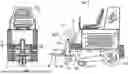
FIG. 6 is a side view of an embodiment of the toothed tool assembly mounted on a motorized floor scraper.
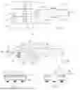
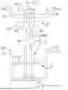
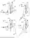
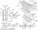
FIGS. 7A-7E are left side, front, rear, top, and oblique views of an embodiment of a riding machine.
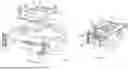
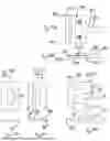
FIGS. 8A & 8B show, respectively, an oblique view of a frame of a riding machine and an exploded view thereof.
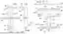
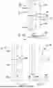
FIGS. 9A & 9B are front and top views of a lift assembly and a portion of a frame of a riding machine, with certain features only shown in FIG. 9B.
FIG. 10A is a front view of a blade slide, and FIG. 10B is a section view along line A-A from FIG. 10A.
FIGS. 11A & 11B are front and top views of a blade swivel.
FIG. 12 is a front view of a pin shaft.
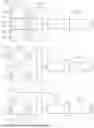
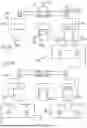
FIGS. 13A-13D show a lift assembly in various positions.
FIGS. 14A-14D show a lift assembly in the same positions as FIGS. 13A-13D with certain features transparent to reveal others.
FIGS. 15A & 15B show top and left views of a blade assembly.
FIGS. 15C & 15D show top and left views of a blade holder base.
FIGS. 15E-15H show, respectively, top, bottom, left, and right views of a blade clamp.
FIGS. 16A & 16B show top and left views of a blade assembly.
FIGS. 16C & 16D show top and left views of a blade holder base.
FIGS. 16E & 16F show top and left views of two blade clamps.
FIGS. 17A & 17B show top views of a blade swivel and blade assemblies and a portion of a frame of a riding machine, in different configurations.
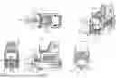
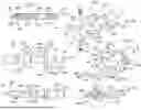
FIGS. 18A-18E are, respectively, top, right side, rear, and two oblique views of an embodiment of a toothed tool assembly, FIG. 18E being an exploded view of FIG. 18D.
FIGS. 19A-19F are, respectively, top, right side, rear, and two oblique views of an embodiment of a toothed tool assembly, FIG. 19E being an exploded view of FIG. 19D. FIG. 19F is a section view along line B-B from FIG. 19E.
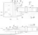
FIGS. 20A-20C top, right side, and rear views of an embodiment of a riding machine.
DETAILED DESCRIPTION OF THE INVENTION
In one embodiment of the invention, as described in detail below, with attention to FIG. 6, toothed tool assembly 1 attaches to scraping assembly 3 mounted on motorized floor scraper 7 by inserting shaft 10 into shaft receiving cylinder 4 and pinning shaft 10 by inserting pin 5 through shaft receiving cylinder 4 and hole 16 in shaft 10. Chisel point 89 on tooth (or teeth) 70 forms an edged structure to be wedged between underlying surface 8 and covering 9 to be removed from surface 8. As floor scraper 7 moves chisel point(s) 89 forward the edged structure strips covering 9 from underlying surface 8.
Turning to FIGS. 1A-ID & 2A-2B, in an embodiment, toothed tool assembly 1 includes tooth support assembly 2 and one or more teeth 70. Tooth support assembly 2 includes shaft 10 and tooth base 30. Shaft 10 is for mounting toothed tool assembly 1 on scraping assembly 3 via shaft receiving cylinder 4 and supports tooth base 30 to support and mount one or more teeth 70. Tooth base 30 is mounted to shaft 10 and has mounting surface 38 for teeth 70 and loading face 52 to apply longitudinal forces to teeth 70. Teeth 70 are roughly rectangular normal to mounting surface 38 and extend past teeth end 32 to expose chisel point(s) 89 extending from side to side for contacting surface 8 to be scraped.
In an embodiment, shaft 10 includes collar 19 to apply compressive forces/longitudinal loading between tooth support assembly 2 of toothed tool assembly 1 and scraping assembly 3. On connecting end 13 of shaft 10, shaft 10 has hole 16 for inserting pin 5 and keyed section 17. On tool end 12 of shaft 10, lower side 21 includes flat deep shoulder 24 and upper side 22 includes tapered section 15 forming flat end shoulder 25. Shoulders 24 and 25 are oriented axially and tool face 26 extends therebetween and faces to lower side 21 normal to shoulders 24 and 25.
In an embodiment, tooth base 30 is mounted by welding to shaft 10 and provides mounting point 36 with flat mounting surface 38 on upper side 42 at teeth end 32 with bolt holes 43 extending through mounting point 36 for teeth 70 to be bolted thereto and to support normal loading forces applied to teeth 70 in use. Mounting point 36 and mounting surface 38 are wide enough to support three teeth 70 at three teeth positions 39. Three bolt holes 43 are provided and spaced apart to provide three teeth positions 39. Teeth positions 39 include one centered on mounting point 36 (and aligned to shaft cut 10) and one to each side thereof. Teeth end 32 of mounting point 36 is cut back at lower side 41 away from mounting surface 38 to avoid contact with surface 8 during operation. Mounting point 36 also includes transverse rail 50 extending outwardly from on upper side 42 between teeth end 32 and shaft end 34. Rail 50 includes loading face 52 (facing tooth end 32) to apply compressive forces/longitudinal loading to teeth 70 and shaft face 54 (facing shaft end 34) and deflector 56 extending toward shaft end 34 from shaft face 34 to apply compressive forces/longitudinal loading to shaft 10 and deflect debris Tooth base 30 includes at shaft end 34, shaft connection 60 including flat shoulder 64 on shaft end 34, and shaft connection face 62 on upper side 42. Flat shoulder 64 and loading face 52 and shaft face 54 are oriented axially, with shaft connection face 62 extending between flat shoulder 64 and shaft face 54 and normal to flat shoulder 64 and shaft face 54. Flat shoulder 64 on shaft end 34 is mounted in contact with deep shoulder 24 on shaft 10 to apply compressive forces/longitudinal loading to shaft 10 with shaft connection face 62 mounted in contact with tool face 26.
Turning to FIGS. 1A-1D, 3A-3B, and 4, in an embodiment, teeth 70 include base face 74 on lower side 81 for contact to mounting surface 38 on mounting point 36, bolt hole 75 larger in size than bolt hole 43 on mounting point 36 between lower side 81 and upper side 82, chisel end 71 cut backwards to form chisel point 89 and base end 72 opposite chisel end 71, with base end forming flat rail face 76. Base face 74 forms a roughly elongated rectangle between chisel end 71 and base end 72 having bolt hole 75 located centrally therein. Chisel end 71 may include carbide insert 88 forming chisel point 89, chisel end 71 having angled pocket 84 for carbide insert 88. Pocket 84 extends between base face 74 on lower side 81 and away from base end 72 on upper side 82, forming insert shoulder 85 at an angle to insert face—Carbide insert 88 is mounted into pocket 84 by welding it to insert shoulder 85 and insert face 86 to place chisel point 89 on the endmost point of tooth 70. The placement of bolt hole 75 and the transverse width of teeth 70 are set to permit side-by-side placement of teeth 70 in teeth positions 39 on tooth base 30. FIG. 4 shows tooth 70 as a tooth blank prior to removal of material to form pocket 84 and prior to insertion of carbide insert 88.
Turning to Figs. 5A-5C, in an embodiment, different teeth configurations 90 are possible by mounting teeth 70 to mounting point 38 in all teeth positions 39 or just one or a fraction of those teeth positions 39. Fig 5A shows full teeth configuration 91 in which all three teeth 70 have been mounted, side-by-side. Such a configuration could have additional teeth if mounting point 38 were so configured. The full teeth configuration 91 permits more covering 9 to be removed per pass but can reduce the ability to remove more difficult materials. FIG. 5B shows gap-toothed configuration 93 in which the two outer teeth 70 have been mounted but the central tooth, aligned with shaft 10, is not mounted (i.e. a 101 configuration where “1” and “0” represent a tooth/no-tooth respectively) thus forming a gap. Such a configuration also could have additional teeth if mounting point 38 were so configured, such as 11011 or 10001 configurations in which there are five teeth or such as 1001 in which there are four teeth. Gap-toothed configuration 93 may permit lifting force to be concentrated on, for example, rows of tiles, and particularly where the centers of the rows are spaced apart by about the spacing between the two teeth 70. FIG. 5C shows center tooth configuration 92 in which only the central tooth 70 aligned with shaft 10 is mounted but the two outer teeth 70 are not (i.e. a 010 configuration). Such a configuration also could have additional teeth if mounting point 38 were so configured, such as 00100 or 01110 configurations in which there are five teeth or such as 0110 in which there are four teeth. Center tooth configuration 92 may permit lifting force to be even more concentrated by reducing the number of teeth and by centering them on the shaft.
The number of teeth 70 and teeth configuration 90 can be changed by removing and/or adding and/or moving one or more teeth 70 to tooth support assembly 2. Mounting a tooth 70 involves placing base face 74 on lower side 81 to mounting surface 38 on mounting point 36, aligning bolt hole 75 to bolt hole 43 on mounting point 36, placing rail face 76 on base end 72 of tooth 70 flush against loading face 52 of rail 50, inserting bolt 45 through holes 75 & 43, and fixing tooth 70 using nut 46 on bolt 45. Demounting a tooth 70 involves reversing that process
Turning to FIGS. 18A-18E & 19A-19F, in an embodiment, toothed tool assembly 201 includes tooth support assembly 202 and one or more teeth 270 Tooth support assembly 202 includes shaft 210 and tooth base 230. Tooth base 230 includes rail section 247 and bolt section 248, as well as shaft face 254 (shaft side) and shaft notch 256. Shaft 210 is for mounting toothed tool assembly 201 on scraping assembly 3 via shaft receiving cylinder 4 (or mounting on socket, e.g. socket 174) and supports tooth base 230 to support and mount one or more teeth 270. Tooth base 230 is mounted to shaft 210 and has mounting surface 238 for teeth 270 and loading face 252 to apply longitudinal forces to teeth 270. Teeth 270 are roughly rectangular normal to mounting surface 238 and extend past teeth end 232 to expose chisel point(s) 289 extending from side to side for contacting surface 8 to be scraped.
In an embodiment, shaft 210 includes collar 219 to apply compressive forces/longitudinal loading between tooth support assembly 202 of toothed tool assembly 201 and scraping assembly 3. On connecting end 213 of shaft 210, shaft 210 has hole 216 for inserting pin 5 and keyed section 217. Tool end 212 of shaft 210 mounts to tooth base 230, and has a circular profile. Tooth base 230, including rail section 247 and bolt section 248, include shaft face 254 and shaft notch 256. Shaft face 254 and tool end 212 are mounted in contact (face-to-face) with one another, and tool end 212 is also in contact with shaft notch 256, both to facilitate mounting (e.g. by welding) shaft 210 to tooth base 230 and pass longitudinal loading to shaft 210.
Tooth base 230 provides six mounting points 236 (FIGS. 18A-18E) or one mounting point 236 (FIGS. 19A-19F) with flat mounting surface 238 on its first, upper side 242, at teeth end 232 with bolt holes 243 through mounting points 236, for the one or more teeth 270 to be bolted thereto using a clamping assembly (e.g. bolts 245 and nuts 246) and to support the normal loading forces applied to the teeth in use. Other numbers of mounting points 236 could be provided, as disclosed above. Teeth end 232 of mounting point 236 is cut back at lower side 241 away from mounting surface 238 to avoid contact with surface 8 during operation. Tooth base 230 includes rail 250 (transverse), on rail section 247, extending outwardly on upper side 242, spaced apart from teeth end 232 and extending to shaft end 234. Bolt section 248 (below) includes mounting surface 238, bolt holes 243. Rail 250 has loading face 252 (tool side), facing tooth end 232, to apply compressive forces/longitudinal loading to teeth 270 at rail face 276
Regarding FIGS. 19A-19F, in an embodiment, tooth base 230 includes single mounting point 236 and single teeth position 239 and supports single tooth 270. Tooth support assembly 202 is otherwise similar to the embodiment in FIGS. 18A-18E but tooth base 230 (and bolt section 247 and rail section 248) include tapered ends 249 narrowing to about the width of tooth 270. In an embodiment, tooth base 270 may include anti-rotation collar 290. Anti-rotation collar 290 includes two extensions 291 and connector 292 connecting extensions 291 to one another and to collar 219, and at least two pins 295 facing toward connecting end 213, and at least one hole 294 each in extensions 291 for mounting pins 295. Pins 295 are each spaced apart from collar 219 and are set at a separation angle about 145 degrees (from shaft centerline).
Turning to FIGS. 18A-18E & 19A-19F, in an embodiment, teeth 270 include base face 274 on lower side 281 for contact to mounting surface 238 on mounting point 236, bolt hole 275 larger in size than bolt hole 243 on mounting point 236 between lower side 281 and upper side 282, chisel end 271 having chisel point 289 and base end 272 opposite chisel end 271, with base end 272 forming rail face 276. Base face 274 forms a roughly elongated rectangle between chisel end 271 and base end 272 having bolt hole 275 located centrally therein. Chisel end 271 may include carbide insert 288 forming chisel point 289, chisel end 271 having pocket 284 for carbide insert 288. Pocket 284 has two insert faces 286 that are substantially symmetrical extending between lower side 281 and upper side 282. Carbide insert 288 has diamond profile 285 (transversely) that is symmetrical. Carbide insert 288 is mounted into pocket 284 by welding it to insert faces 286 to place chisel point 289 on the endmost point of tooth 270.
Turning to FIGS. 7A-7E, 8A-8B, 13A-13D & 14A-14D, in an embodiment, riding machine 100 includes frame 101, including parallel substantially flat frame rails 102 that are connected by cross-pieces 106, and top surface 107. Mounted to frame rails 102 are rear wheels 104 and front wheel assembly 105. Mounted to the front of top surface 107 is a pair of arms 112 supporting upper lift cylinder anchor 113. Set into top surface 107 is blade storage slot, including blade support channel and opposing finger-grip areas. Frame rails 102 extend from front to rear of frame 101. Front ends 103 of frame rail 102 include lift assembly slots 115, including one each upper lift assembly slot 116 and lower lift assembly slot 117 on each side Slot length 118 of lift assembly slots 115 is at least as great as lift 122 between working elevation 121 and off-floor elevation 120.
Turning more broadly to all FIGS. 7A-14D, in an embodiment, riding machine 100 also includes lift assembly 130, including slide assembly 131, and tool assembly 108 (such as blade assembly 180 or toothed tool assembly 1 or 201.
Slide assembly 131 includes blade slide 140 and blade swivel 160, where tool assembly 108 is removably fixed to blade swivel 160. Slide assembly 131, particularly blade slide 140 and lift assembly slots 115 in frame rails 102 cooperate to permit lift assembly 130 to lower tool assembly 108 from off-floor elevation 120 to working elevation 121 and to lift the tool assembly from working elevation 121 to off-floor elevation 120. Blade swivel 160, rotatably mounted to blade slide 140, cooperate to permit lift assembly 130 to rotate blade swivel 160 down from off-floor tilt 123 to working tilt 124 (as selected) and to rotate blade swivel 160 up from working tilt 124 to off-floor tilt 123. Lowering and lifting of blade slide 140, and slide assembly 131, and lift assembly 130, can occur without altering rotation of blade swivel 160 and without altering working angle 125 applied by the operator.
Slide assembly 131 includes blade slide 140, blade swivel 160, lift cylinder 132, and tilt cylinder 133.
Blade slide 140 includes center lift rails 142 connected near bottom 144 by fixed pin tube 150 and near the center at center pin tube 146 (extending beyond side 145 of rails 142). Center pin shaft 147 extends through center pin tube 146 and its ends 148 extend beyond ends of center pin tube 146 to each side to fit into upper lift assembly slots 116. Center lift rails 142 include upper tilt cylinder anchor 152, fixed to upper tilt cylinder mounting point 154 near top 143 and offset forward from center pin tube 146, and lower lift cylinder anchor 153, fixed to lower lift cylinder mounting point 156 near bottom 144 and offset rearward from fixed pin tube 150.
Blade swivel 160 includes plate 162 with pin end 166 towards rear 163 and socket end 167 forward 164, and which is tapered toward socket end 167. Pin end 166 includes a set of swivel pin tubes 169, spaced apart to permit alignment to fixed pin tube 150 and to sides of lift rails 102 (and to lift assembly slots 115). Swivel pin shaft 170 passes through fixed pin tube 150, lift rails 142, and swivel pin tubes 169, and its ends 171 extend beyond the ends of each swivel pin tube 169 to each side Ends 171 of swivel pin shaft 170 fit into lower lift assembly slots 117. Socket end 167 includes socket 174 for connecting to tool assembly 108, typically centerline 161 to blade slide 140 and blade swivel 160. Socket end 169 also includes lower tilt cylinder anchor 184 on top 165.
In another embodiment, shown in FIGS. 17A-17B, blade swivel 160 is wider at socket end 169 to accommodate multiple sockets for connecting to one tool assembly each (here shown as blade assembly 180). Here, three sockets are fixed to plate 162, with central socket 175 on centerline and two side sockets 176, one each to each side of central socket 176.
Blade swivel 160 can rotate about an axis of swivel pin shaft 169 to and from working angle 125. Blade slide 140, and lift assembly 130, can slide up and down, vertically or at an angle to vertical, along upper lift assembly slots 116 and lower lift assembly slots 117 on ends 148 of center pin shaft 147 and ends 171 of swivel pin shaft 170. Rotation and sliding are independent; the entire lift assembly 130 slides, moving blade swivel 160 up and down with it without changing working angle 125. Rotation can also take place without changing the elevation.
Elevation is altered by operating hydraulic lift cylinder 132 connected to frame 101 at upper lift cylinder anchor 113 and to lift assembly 130 at lower lift cylinder anchor 153 on slide rails 142 (shown in FIG. 9B but omitted for clarity in FIG. 9A). Extending lift cylinder 132 forces lift assembly 130 down to working elevation 121, which may lift front wheel assembly 105 off surface 8 to place weight on tool assembly 108 if blade swivel 160 is at working tilt 124. Retracting lift cylinder 132 lifts lift assembly 130 up from working elevation 121 to off-floor elevation 120, which should lift tool assembly 108 off the floor. Lift 122 is the distance between working elevation 121 and off-floor elevation 120.
Tilt is altered by operating hydraulic tilt cylinder 133 connected at upper tilt cylinder anchor 154 on slide rails 142 of slide assembly 131 and blade swivel 160 at lower tilt cylinder anchor 172. Extending tilt cylinder 133 forces blade swivel 160 down to working tilt 124, which may lift front wheel assembly 105 off surface 8 to place weight on tool assembly 108 if lift assembly 130 is at working elevation 121. Retracting tilt cylinder 133 lifts blade swivel 160 up from working tilt 124 to off-floor tilt 123, which should lift tool assembly 108 off the floor.
Turning in particular to FIGS. 15A-15H & 16A-16F, in an embodiment where tool assembly 108 takes the form of blade assembly 180, blade assembly 180 includes blade holder base 181 and one or more blade clamps 190, to hold in place blade 199 used for removing floor covering 9 from surface 8.
Blade holder base 181 includes shaft section 182, for removable and locking insertion into, e.g., socket 174 of blade swivel 160, plate 162 including transverse stop 185 extending upward therefrom, and clamp surface 186 forward of stop 185.
Blade clamp(s) 190 include transverse recess 191 to receive transverse stop 185, and clamp surface 192 forward of recess 191
Bolt holes 194 are provided in both blade holder base 181 and blade clamp 190 for removably clamping and locking blade 199 between clamp surfaces 186, 192 and against transverse stop 185 to supporting axial and vertical scraping forces on blade 199.
Blade holder base 181 may hold one blade 199 and include single blade clamp 190 of similar length to blade 199 and blade holder base 181, where blade clamp 190 includes central notch 197 to accommodate shaft section 182 fixed to plate 184. Or blade holder base 181 may hold two (or more) blades 199, and include two (or more) blade clamps 190 of similar length to blades 199, where blade holder base 181 is of the combined lengths, and where blade clamps 186, 192 include cutaway 198 (which may be on an end thereof) to accommodate shaft section 182 fixed to plate 184.
Turning to FIGS. 20A-20C, and with reference to FIGS. 9A-9B, 10A-10B, 11A-11B, and 12, in an embodiment a riding machine 100 is similar to that described above (and is numbered the same), but is designed for a rider standing on platform 114 and facilitates that rider seeing tool assembly 108 (e.g. blade assembly 180) over components of lift assembly 130. FIGS. 13A-13D, 14A-14D are also relevant to show, mutatis mutandis, the four positions taken by lift assembly 130 in operation (two each for elevation and tilt, with FIG. 20B reflecting the position shown in FIGS. 13C & 14C).
Differences from the embodiment above include that lift assembly slots 115, including upper lift assembly slots 116 and lower lift assembly slots 117, are non-vertical and are angled backward at repose angle 119, which is fixed relative to frame 101. Similarly, front ends 103 of frame rails 102, may be angled backward relative to vertical, and may also be at repose angle 119. Repose angle is about 35 degrees. As lift assembly slots 115 are at repose angle 119, and center pin shaft 147 and swivel pin shaft 170 are set therein to slide upward and downward between off-floor elevation 120 and working elevation 121, blade slide 140, including center lift rails 142, is also at repose angle 140, as is lift cylinder 132. Lift cylinder 132 is mounted to upper lift cylinder anchor 113, which is connected to frame 101.
Claims
1. A toothed tool assembly for scraping a surface, comprising:
a shaft;
a tooth base;
the tooth base having a tooth end and a shaft end;
the tooth base mounted to the shaft at the shaft end;
the tooth base having a loading face transversely therebetween; and
the tooth base having a mounting point between the tooth end and the loading face; and
the mounting point comprising a mounting surface and at least one teeth position.
2. The toothed tool assembly of claim 1, further comprising:
one or more teeth, the one or more teeth each comprising:
a chisel end;
a rail face; and
a base face between the chisel end and rail face;
the base face mounted to said mounting point; and
the chisel end extending beyond the tooth base.
3. The toothed tool assembly of claim 2, further comprising:
the rail face mounted against the loading face.
4. The toothed tool assembly of claim 3, further comprising:
the rail face in compressive loading on the loading face.
5. The toothed tool assembly of claim 1, further comprising:
the base face of the one or more teeth compressed by a bolt to the mounting surface.
6. The toothed tool assembly of claim 1, further comprising:
one or more teeth, the one or more teeth each comprising:
a chisel end;
a base face;
the base face mounted to said mounting point; and
the chisel end comprising a carbide insert;
the carbide insert having a diamond profile.
7. The toothed tool assembly of claim 1:
the mounting point comprising at least three teeth positions.
8. The toothed tool assembly of claim 7:
the at least three teeth positions comprising a first teeth position aligned to the shaft and having at least one teeth position to either side of the first teeth position.
9. The toothed tool assembly of claim 7, further comprising:
one or more teeth, the one or more teeth each comprising:
a chisel end;
a base face;
the base face mounted to said mounting point; and
a teeth configuration selected from the group of: full teeth configuration, center tooth configuration, and gap-toothed configuration.
10. The toothed tool assembly of claim 1, further comprising:
a rail extending outwardly from the mounting surface;
the rail comprising the loading surface;
11. The toothed tool assembly of claim 10:
the rail extending toward the shaft end from said loading surface.
12. The toothed tool assembly of claim 10:
the rail extending between the loading surface and the shaft.
13. The toothed tool assembly of claim 1:
the mounting point comprising a single teeth position; and
the tooth base comprising a tapered section.
14. The toothed tool assembly of claim 1:
the shaft having a tool end and a connecting end; and
the connecting end mounted on a riding machine.
15. The tooth for scraping surfaces, comprising:
a chisel end;
a rail face opposite the chisel end; and
a base face between the chisel end and rail face;
the chisel end comprising a carbide insert;
the carbide insert having a diamond profile.
16. The tooth of claim 15, further comprising:
a pocket for the carbide insert;
the pocket comprising opposing symmetrical insert faces; and
said carbide insert welded to said insert faces.
17. The tooth of claim 16, further comprising:
an upper side opposing the base face; and
the insert faces extending between the base face and the upper side.
18. The tooth of claim 15, further comprising:
an upper side opposing the base face; and
a bolt hole through the upper side and the base face.
19. A riding machine, comprising:
a frame comprising at least one lift assembly slot on either side of the riding machine; and
an adjustable lift assembly comprising,
a slide assembly, comprising
a blade swivel, comprising
a swivel pin shaft along a transverse axis to the lift assembly slots; and
one or more sockets for receiving a shaft;
a blade slide, comprising
center pins along the transverse axis to the lift assembly slots;
the slide assembly upwardly slidable relative to the frame on the center pins and swivel pin shaft along the lift assembly slots; and
the blade swivel rotatable along the transverse axis about the swivel pin shaft.
20. The riding machine of claim 19,
the frame comprising at least an upper lift assembly slot and a lower lift assembly slot on either side; and
the swivel pin shaft having ends;
the swivel pin ends in the lower lift assembly slots; and
the center pins in the upper lift assembly slots.
21. The riding machine of claim 19,
the frame comprising a pair of frame rails;
each said frame rail comprising at least one of said lift assembly slots.
22. The riding machine of claim 19,
the blade slide further comprising
at least one center lift rail; and
a center pin tube connected to said center pins; and
a fixed pin tube connected to the swivel pin shaft.
23. The riding machine of claim 22,
the at least one center lift rail having a bottom;
the at least one center lift rail connected near the bottom to the fixed pin tube; and
the at least one center lift rail connected to the center pin tube.
24. The riding machine of claim 22,
the blade slide further comprising a pair of center lift rails; and
the center lift rails having a bottom;
the center lift rails connected near the bottom by the fixed pin tube; and
the center lift rails connected by the center pin tube.
25. The riding machine of claim 19,
the blade swivel further comprising at least one swivel pin tube;
the blade slide further comprising a fixed pin tube; and
the swivel pin shaft passing through the at least one swivel pin tube and the fixed pin tube.
26. The riding machine of claim 19:
the blade swivel comprising three sockets.
27. The riding machine of claim 19, further comprising:
an extendable and retractable lift cylinder connected to the blade slide and to the frame.
28. The riding machine of claim 27,
the lift cylinder for sliding the slide assembly between a working elevation and an off-floor elevation.
29. The riding machine of claim 19, further comprising:
an extendable and retractable tilt cylinder connected to the blade slide and to the blade swivel.
30. The riding machine of claim 29,
the tilt cylinder for rotating the blade swivel between a working tilt and an off-floor tilt.
31. The riding machine of claim 19, further comprising:
a tool assembly, comprising one selected from a blade assembly and a toothed tool assembly:
the tool assembly connected to the one or more sockets on the blade swivel.
32. The riding machine of claim 31:
the blade swivel comprising three sockets; and
at least one of said sockets is positioned off a centerline of the blade swivel to position at least part of the tool assembly past a side of the riding machine.
33. The riding machine of claim 31, further comprising:
one or more blade assemblies for clamping a scraping blade, comprising
a blade holder base, having a shaft section and a plate section; and
one or more blade clamps, adjustably fixed to the blade holder base against the plate section.
34. The riding machine of claim 31, further comprising:
one or more toothed tool assemblies for supporting teeth, comprising
a shaft;
a tooth base;
the tooth base having a tooth end and a shaft end;
the tooth base mounted to the shaft at the shaft end;
the tooth base having a loading face transversely therebetween; and
the tooth base having a mounting point between the tooth end and the loading face; and
the mounting point comprising a mounting surface and at least one teeth position.
35. The riding machine of claim 19,
said lift assembly slots at a repose angle of about 30-40 degrees.
36. A method of adjusting height and working angle of a tool assembly on a riding machine, comprising:
sliding a slide assembly upwardly relative to a frame of the riding machine on center pins and a swivel pin shaft along at least one lift assembly slot on either side of the riding machine;
rotating a blade swivel about the swivel pin shaft along a transverse axis to the lift assembly slots;
the sliding step comprising sliding the blade swivel independently of rotating the blade swivel; and
the rotating step comprising rotating the blade swivel independently of sliding the slide assembly.
37. The riding machine of claim 36,
the blade swivel comprising one or more sockets for receiving a shaft for a tool assembly.
38. The riding machine of claim 36,
the sliding step further comprising sliding a blade slide comprising the center pins and connected to the swivel pin shaft.
39. The riding machine of claim 36,
the sliding step further comprising operating a lift cylinder to slide the slide assembly between a working elevation and an off-floor elevation.
40. The riding machine of claim 39,
the slide assembly further comprising a blade slide, the blade slid comprising the center pins and connected to the swivel pin shaft; and
the operating a lift cylinder step comprising extending and retracting the lift cylinder, the lift cylinder being connected to the blade slide and to the frame.
41. The riding machine of claim 36,
the rotating step further comprising operating a tilt cylinder to rotate the blade swivel between a working tilt and an off-floor tilt.
42. The riding machine of claim 41,
the slide assembly further comprising a blade slide, the blade slid comprising the center pins and connected to the swivel pin shaft; and
the operating a tilt cylinder step comprising extending and retracting the tilt cylinder, the lift cylinder being connected to the blade slide and to the blade swivel.
Images & Drawings included:


Sources:
- United States Patent and Trademark Office - verify current appl. status at the USPTO↗
Recent applications in this class:
- » 20240426118 2024-12-26
TOOL TO REMOVE PAD FROM UNDERNEATH INSTALLED OR PARTIALLY REMOVED CARPET - » 20230374802 2023-11-23
FLOOR STRIPPER MACHINE - » 20230374801 2023-11-23
Wheel coupler and scraper for floor stripper - » 20230265670 2023-08-24
RAISED FLOOR PANEL REMOVAL TOOL - » 20220381049 2022-12-01
Blade control system and flooring removal machines incorporating the same - » 20210324643 2021-10-21
Carpet tile lifting apparatus and system for removing carpet tiles - » 20210293041 2021-09-23
Carpet pulling apparatus and system for removing carpet - » 20210277674 2021-09-09
Dual-use flooring installation device with interchangeable tool-ends - » 20210238873 2021-08-05
Carpet Cutting Apparatus and A Method and System for Removing Carpet Bonded To A Floor - » 20200190835 2020-06-18
Blade arrangement