MODULAR PREFAB DELIVERY SYSTEM
US20250172007A1
2025-05-29
18/956,839
2024-11-22
Smart Summary: A modular pod is designed for building prefabricated homes, featuring a strong steel frame made of top and bottom rings connected by columns. This system helps streamline the construction, shipping, and delivery of modular buildings. Modular homes are popular because they are usually cheaper and faster to build compared to traditional homes. They can also be customized to fit the homeowner's needs and are often more energy-efficient. The new design aims to prevent damage during transportation, which is a common issue with conventional modular buildings. 🚀 TL;DR
Abstract:
A modular pod for a prefabricated modular building includes a top rectilinear ring of steel beams, a bottom rectilinear ring of steel beams and a plurality of steel columns connecting the top rectilinear ring of steel beams and the bottom rectilinear ring of steel beams. A prefabricated module home delivery system includes the modular pod, an infill frame disposed within the modular pod and a protective sheathing disposed around the modular pod.
Interested in similar patents?
Get notified when new applications in this technology area are published.
Classification:
E04H1/12 » CPC main
Buildings or groups of buildings for dwelling or office purposes; General layout, e.g. modular co-ordination, staggered storeys small buildings Small buildings or other erections for limited occupation, erected in the open air or arranged in buildings, e.g. kiosks, waiting shelters for bus stops or for filling stations, roofs for railway platforms, watchmens' huts, dressing cubicles
E04H2001/1283 » CPC further
Buildings or groups of buildings for dwelling or office purposes; General layout, e.g. modular co-ordination, staggered storeys small buildings; Small buildings or other erections for limited occupation, erected in the open air or arranged in buildings, e.g. kiosks, waiting shelters for bus stops or for filling stations, roofs for railway platforms, watchmens' huts, dressing cubicles Small buildings of the ISO containers type
Description
CROSS REFERENCE TO RELATED APPLICATIONS
This application claims priority of U.S. Provisional Application No. 63/602,576 filed on Nov. 25, 2023 under 35 U.S.C. § 119(e), the entire contents of all of which are hereby incorporated by reference.
BACKGROUND OF THE INVENTION
Field of the Invention
The present invention generally relates to prefabricated modular building and home construction and more particularly to a modular framing system designed to streamline and safeguard the construction, shipment, and delivery of modular buildings and components.
Description of the Related Art
Modular homes and other buildings have increased in popularity and use. Modular homes are typically 10% to 20% less expensive than traditionally built homes. Additionally, modular homes can be built up to 60% faster than stick-built homes. Modular homes allow a homeowner to be customized to suit their needs, both in terms of layout/square footage and features. Finally, modular homes can be more energy-efficient than traditionally built houses, and the materials and building process may be more environmentally friendly as well.
Conventional modular buildings tend to suffer from damage during transportation. For example, during transportation, wood and sheetrock stress cracks are common. Additionally, wood frames can be damaged during transportation and overtime after construction. Finally, conventional modular buildings do not offer sufficient resistance to severe weather, in particular high winds and rain.
Furthermore, despite the advantages of modular buildings, builders and developers frequently encounter challenges during the transportation of modular or prefabricated structures, regardless of the intended market. Conventional modular frames are often damaged during long-distance shipping over land, air, and sea, with wood frames especially prone to cracking and structural distortion under transport stresses. Additionally, many port facilities, particularly older or limited ones, lack the necessary infrastructure to manage the secure and efficient delivery of large or heavy modular units.
Beyond shipping issues, traditional modular buildings and homes often lack flexibility for customization. Many structures are proprietary, conforming to specific floor framing, ceiling framing, cladding, foundation, roof framing, and specific modular configurations, which restricts adaptability and limits options for accommodating diverse architectural and functional requirements.
Furthermore, conventional modular systems are also limited in that they lack design flexibility and lack compatibility with a variety of material options. Structural elements required for shear resistance in wood structures requires significant paneling along long wall runs and limits uninterrupted sections of openings or glass.
Another challenge with conventional wood framing systems is the requirement for sequential vertical assembly. Floors must be constructed first, followed by walls, and then the ceiling or roof. This step-by-step process is inherently inefficient and significantly extends fabrication time.
Conventional framing systems reveal significant limitations during craning operations. These systems necessitate lighter loads and smaller module sizes to ensure lifting will not damage the wood structure. Additionally, installing rigging points in wooden substrates presents challenges, as heavier loads risk pulling eyes or hooks out of position. Consequently, strapping often becomes the only viable method for crane lifting, which can compromise the integrity of the wooden structure.
SUMMARY OF THE INVENTION
In view of the foregoing and other exemplary problems, drawbacks, and disadvantages of the conventional methods and structures, an exemplary feature of the present invention is to provide modular building components with improved protection during delivery/shipment.
In a first, exemplary, non-limiting aspect of the present invention, a modular pod includes a top rectilinear ring of steel beams, a bottom rectilinear ring of steel beams and a plurality of steel columns connecting the top rectilinear ring of steel beams and the bottom rectilinear ring of steel beams.
In a second, exemplary, non-limiting aspect of the present invention, a prefabricated module home includes a modular pod, the modular pod including a top rectilinear ring of steel beams, a bottom rectilinear ring of steel beams and a plurality of steel columns connecting the top rectilinear ring of steel beams and the bottom rectilinear ring of steel beams.
In a third, exemplary, non-limiting aspect of the present invention, a prefabricated module home delivery system includes a modular pod, an infill frame disposed within the modular pod and a protective sheathing disposed around the modular pod. The modular pod includes a top rectilinear ring of steel beams, a bottom rectilinear ring of steel beams and a plurality of steel columns connecting the top rectilinear ring of steel beams and the bottom rectilinear ring of steel beams.
In accordance with the above, exemplary aspects of the present invention, a method and system are provided in which protection of the modular components is improved during delivery/shipment.
The present invention uses steel frames for the prefabricated modular pods. Specifically, the present invention uses structural steel, but can also be made from other materials like, for example, aluminum. The steel beams can be provided in several configurations including, but not limited to, hollow steel sections (HSS) tubes, W-section beams, castellated beams, cellular beams, and other structural shapes. The use of steel in the modular pods provides several important benefits. First, the use of a steel frame in the modular pods provides protection for internal components during shipping, whether by land or sea. Second, after the modular pods are assembled to build the home or building, the steel provides improved resistance to severe weather like, for example, hurricanes. Steel also spans further allowing for maximum flexibility for windows and window locations. The steel frame allows for a variety of roof configurations including, for example, wood trusses installed above the steel frame and flat, concrete roofs.
The modular steel frame of the present addresses the limitations of conventional modular systems by offering a design that not only improves durability and shipment resilience but also provides a flexible framework adaptable to various construction and customization needs, supporting broader applications in modular construction.
Compared to conventional wood frames, steel has less movement over time. That is, wood will shrink and expand due to moisture content, which is not an issue with steel. Additionally, if steel is protected correctly it is more durable and will last longer than wood. Finally, steel provides stronger connections when placing the pods into position at the building site.
Conventional modular systems often encounter significant challenges during installation, including issues with alignment and securing connections. The modules in the present invention overcome these challenges by utilizing alignment rods and weldable connections, ensuring a more precise fit. Steel frames further enhance accuracy by delivering consistent and predictable dimensional stability and structural integrity. In contrast, wood frames in conventional systems are prone to variability due to expansion and contraction, resulting in less reliable alignment.
The present invention exhibits reduced distortion and vibration during shipment, effectively preventing cracking in materials such as sheetrock, tile, and wood. Its rigidity during transport and post-construction also protects secondary framing elements—such as walls, floors, and ceilings—as well as internal components and finishes, ensuring they remain undamaged throughout the process.
The present invention enables significantly faster construction. Unlike conventional wood framing systems, which require sequential vertical assembly (a process often plagued by inefficiency) the steel frames of this invention provide a strong skeletal frame. Once fabricated, the remaining components can be installed within the structure, allowing simultaneous construction in both vertical and horizontal directions, greatly accelerating the overall process.
Conventional framing systems require lighter loads and smaller units to make craning feasible. Installing rigging points such as eyes and hooks in wood substrates is particularly challenging, often necessitating lighter loads or strapping as the sole option for crane lifting. In contrast, the steel frames of the present invention offer superior rigidity, supporting longer dimensions even under the gravity load pressure of craning, with significantly reduced risk of deflection or distortion. Steel also accommodates heavier loads, enabling the use of larger, more complete units, and allows for welded rigging points that simplify craning without reliance on strapping. Moreover, when strapping is unavoidable on a project site, steel's enhanced rigidity minimizes the risk of damage caused by strap pressure at the corners of modular units.
Steel, as used in the frames of the present invention, allows for larger units with longer spans that can extend beyond standard trailer lengths and widths and greater spans between supports when placed on the construction site.
BRIEF DESCRIPTION OF THE DRAWINGS
The foregoing and other exemplary purposes, aspects and advantages will be better understood from the following detailed description of an exemplary embodiment of the invention with reference to the drawings, in which:
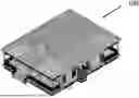
FIG. 1 illustrates a modular home 100 according to certain exemplary embodiments of the present invention;
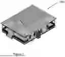
FIG. 2 illustrates an exploded view of the modular home 100;
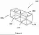
FIG. 3 illustrates the components of a modular pod 200 according to certain exemplary embodiments of the present invention;
FIG. 4 illustrates an exploded view of the steel structural frame of modular pod 200;
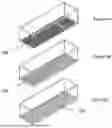
FIGS. 5A-5C illustrate various embodiments of the modular pod with floor structure;
FIGS. 6A-6C illustrate various embodiments of the modular pod with ceiling structure;
FIGS. 7A (perspective view) and 7B (top view) illustrate the modular pod with room partitions;
FIG. 8A-8C illustrate various embodiments of the modular pod with cladding types;
FIG. 9 illustrates an end view of the steel cage of the modular pod 200;
FIG. 10 is an enlarged view of a feature of the steel cage of the modular pod 200;
FIG. 11 illustrates several modular pods to be connected together;
FIG. 12 illustrates several modular pods connected together;
FIG. 13A illustrates a foundation structure 600 for a modular pod;
FIG. 13B illustrates the modular pods mounted on the foundation;
FIGS. 14A-14C illustrate various the modular pods with various versions of a roof mounted thereon;
FIG. 15 illustrates a prefabricated modular building delivery system according to certain exemplary embodiments of the present invention;
FIG. 16A illustrates an exploded view of a sheathing 1006;
FIG. 16B illustrates the sheathing 1006B on a modular pod;
FIGS. 17A and 17B illustrate a waterproof cover 1004;
FIG. 18 illustrates a concrete footing 602 of a foundation for the modular pod;
FIGS. 19A and 19B illustrate embodiments of foundation base plate 603;
FIGS. 20 and 21 illustrate various exemplary configurations of modular pods; and
FIGS. 22A and 22B illustrate rigging points and alignment rods for craning modular pods into place.
DETAILED DESCRIPTION OF EXEMPLARY EMBODIMENTS OF THE INVENTION
Referring now to the drawings, and more particularly to FIGS. 1-22B, there are shown exemplary embodiments of the method and structures according to the present invention.
FIG. 1 illustrates a prefabricated modular home 100 build using the claimed invention. The home 100 illustrated in FIG. 1 depicts an exemplary beach cottage. The claimed invention, as described herein, however, is not limited to the beach cottage example illustrated in FIG. 1. Indeed, the components described in the following description can be assembled in any configuration as desired to create any type, shape or model or home or building. The beach cottage home 100 illustrated in FIG. 1 is provided merely for exemplary purposes and in no way is intended to limit the scope of the present invention.
FIG. 2 illustrates an exploded view of the prefabricated modular home 100 and its individual components. As is illustrated in FIG. 2, the prefabricated modular home 100 is made up of one or more modular pods 200 according to certain exemplary embodiments of the present invention. In the exemplary embodiment illustrated in FIG. 2, the prefabricated modular home 100 includes three (3) modular pods 200. The prefabricated modular home (or building) 100 can include one or any number of modular pods 200. In addition to the modular pods 200, the home 100 may include additional exterior components. For example, in the beach cottage illustrated in FIGS. 1 and 2, the external components includes a rear porch 300, a front porch 400 and a roof 500. In accordance with certain exemplary aspects of the invention, the modular pods 200 are constructed in advance and then delivered to the location of the home. The external components including, for example, the side porch 300, the front porch 400 and the roof 500, can be constructed at the location of the home and secured to the modular pods 200 onsite.
Additionally, referring again to FIG. 2, the pod may include walls 210, windows 212 and doors 214. The floors and ceilings may be infilled with a structural support material such as, for example, wood, steel or concrete. Additionally, the walls 210 may be constructed with a structural support material such as, for example, wood, aluminum, steel or concrete to create open or closed structures with windows 212 and doors 214.
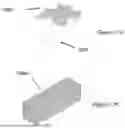
FIGS. 3 and 4 illustrates a frame 202 of one of the modular pods 200 illustrated in FIG. 2. FIG. 3 illustrates the frame 202 assembled while FIG. 4 illustrates the frame in an exploded view. The frame 202 is a steel cage. The frame 202 includes a top rectilinear ring of steel beams 203, a bottom rectilinear ring of steel beams 204 and a plurality of steel columns 205/206 connecting the top rectilinear ring of steel beams and the bottom rectilinear ring of steel beams. The plurality of steel columns include at least a plurality of corner columns 205 disposed at the four corners of the frame. Additionally, depending on the size (e.g., length) of the modular pod 200, the plurality of steel columns may also include one or more intermediate columns 206 disposed along the length of the frame 202. The intermediate columns 206 provide additional support, both during transportation and upon building. Further, depending on the size of the modular pod 200, the frame may include intermediate steel beams 207 for additional structural support.
The steel frame 202 illustrated in FIG. 3 includes three generally rectilinear, cube-shaped portions, A, B and C. At a minimum, the frame 202 will include a single rectilinear cube-shaped portion A. Depending on dimensions of the modular home 100, the frame 202 of the modular pod 200 will include two, three or any number of rectilinear cube-shaped portions to provide sufficient length.
FIGS. 5A-5C illustrate exemplary embodiments of the modular pods 200 illustrating various floor framing 208 options. FIG. 5A illustrates a floor framing 208 made of wood trusses, FIG. 5B illustrates a floor framing 208 made of steel beams, and FIG. 5C illustrates a floor framing 208 made of a concrete slab. The floor framing 208 can be pre-installed within the modular pod 200 to be shipped with the modular pod 200.
FIGS. 6A-6C illustrate exemplary embodiments of the modular pods 200 illustrating various ceiling 209 options. FIG. 6A illustrates a ceiling 209 made of wood trusses, FIG. 6B illustrates a ceiling 209 made of steel beams, and FIG. 6C illustrates a ceiling 209 made of a concrete slab. The ceiling 209 can be pre-installed within the modular pod 200 to be shipped with the modular pod 200.
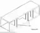
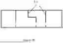
FIGS. 7A and 7B illustrate flexible configurations of interior partitions 211 created by wood, steel, aluminum, or steel infill framing. The partitions 211 are configured to provide separate rooms, doorways and hallways. The partitions 211 can be flexibly designed into any desired configuration or layout. The partitions 211 can be pre-installed within the modular pod 200 to be shipped with the modular pod 200.
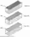
FIGS. 8A-8C illustrate exemplary embodiments of the modular pods 200 illustrating various exterior cladding 213 options. FIG. 8A illustrates an exterior cladding 213 made of wood or cementitious material installed horizontally, vertically, or in panels, FIG. 6B illustrates an exterior cladding 213 made of steel baffles for blast-proof construction applications, and FIG. 8C illustrates an exterior cladding 213 made of glass. The exterior cladding 213 can be pre-installed within the modular pod 200 to be shipped with the modular pod 200.
FIG. 9 illustrates an end view of the steel frame 202. As is illustrated in FIG. 9, each steel frame 202 includes a C-section steel beam 207 disposed along a top and a bottom of the frame 202. The C-section steel beam is disposed on a side of the steel frame 202 that will form an intersection between end module pods and interior modular pods. C-section steel beams are used so that when combined with a C-section steel beam of an adjacent pod, the two C-section steel beams will make a combined W-section shape
The steel frame 202 may also include a steel I-beam 206 disposed along a top and a bottom of the frame 202. FIG. 10 illustrates an enlarged view of the I-beam 206 attached to, for example, the top rectilinear ring of steel beams 203. Additionally, as opposed to the above beam configurations, an exemplary embodiment of the invention uses HSS breams for all of the steam beams in the frame 202.
FIG. 11 illustrates the steel frame 202 of three modular pods 200 to be connected to one another. The three module pods include a first exterior pod 200A, an interior pod 200B and a second exterior pod 200C. Again, the number of modular pods 200 to be connected is not limited to the number and/or configuration illustrated in FIG. 11. For example, any number of additional interior modular pods 200B could be included between the first exterior pod 200A and the second exterior pod 200C. The first exterior pod 200A and a second exterior pod 200C have I-beams 206 on their exterior ends and C-section steel beams 207 on their exterior ends. The interior pod 200B, however, has C-section steel beams 207 on both ends so that the interior pod 200B can be connected on each side to another pod. FIG. 12 illustrates the first exterior pod 200A, the interior pod 200B and the second exterior pod 200C connected together, forming one series of interior spaces of the modular home 100. In accordance with certain exemplary embodiments of the invention, the first exterior pod 200A, the interior pod 200B and the second exterior pod 200C are welded together. The welding technique can be any contemplated or currently used welding technique in the building construction industry. The pods are individually transported to a building site (e.g., location on which the home 100 will be built) and then welded.
Before the pods 200 are welded together, they are mounted onto a foundation, as is illustrated in FIGS. 13A and 13B. The pod 200 is lifted, for example by a crane, and placed on the foundation 600. The foundation 600 can be any foundation material and configuration including, for example, a pier, wall, beams, piles, or footings, etc. After the pods 200A, 200B, 200C are secured to the foundation, they are then welded or bolted together.
FIG. 14A illustrates a roof 500 secured on top of the pods 200A, 200B, 200C. The roof may be formed in any shape and any material. For example, the roof may be made of wood trusses or wood framing, or may be a flat concrete roof. FIG. 14B illustrates an exemplary roof 500b in accordance with certain exemplary embodiments of the invention. The roof 500B in FIG. 14B is a wood truss gable roof. FIG. 14C illustrates another exemplary roof 500B in accordance with certain exemplary embodiments of the invention. The roof 500c in FIG. 14C is a flat wood truss roof.
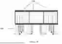
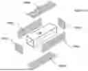
As noted, the modular pods 200 are prefabricated and then delivered/shipped to a building site. FIG. 15 illustrates a prefabricated module pod delivery system 1000. The system 1000 includes a pod 200. The system 1000 also includes a framing infill 1002. The framing infill 1002 is an frame positioned within the steel frame of the pod 200. The infill frame can be constructed with wood, aluminum, or steel. The infill frame forms the elements of the residential or commercial structure (e.g., modular home 100) and contains one or more of an exterior wall, interior partition, ceiling, floor, etc. In accordance with certain exemplary embodiments of the invention, the framing infill 1002 may include further interior finishes such as, for example, floor finish (e.g., wood, tile, etc.), cabinets, countertops, etc. That is, as discussed above, the flooring 208 (FIGS. 5A-5C), the ceiling 209 FIGS. 6A-6C) and the partitions 211 (FIGS. 7A and 7B) are included in the modular pod 200 at this time.
Additionally, the system 1000 also includes a sheathing 1006. The sheathing 1006 is further illustrated in FIGS. 16A and 16B. The sheathing 1006 includes several portions, as illustrated in FIG. 16A, which are secured over the modular pod 200. The sheathing 1006 includes a top portion 1006a, a bottom portion 1006d, two side portions 1006b and two end portions 1006c. The sheathing 1006 is placed over the pods 200 for transport and some or all of the sheathing is removed once the pods 200 are delivered to the building site. FIG. 16B illustrates the sheathing 1006 applied to the modular pod 200. Typically, once the modular pods 200 are installed at the building site, the top portion 1006a and the bottom portion 1006b of the sheathing remain in place while the end portions 1006c and the side portions 1006b are removed. The sheathing 1006 can be made of wood, cementitious material, plastic, metal, or fiberglass.
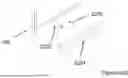
The system 1000 also includes waterproofing 1004. FIG. 17A illustrates the waterproofing 1004 as it is being applied to the modular module 200 and FIG. 17B after it is being applied to the modular module 200. The waterproofing 1004 is placed over and around the pods 200 (and placed over and around the sheathing 1006) for transport and removed once the pods 200 are delivered to the building site. The waterproofing can provide additional watertight protection during transit.
The system 1000 also includes the foundation 600, which is constructed at the building site. In the exemplary embodiment illustrated in FIG. 15, the foundation 600 includes concrete footings 602 and steel connectors 604 for mounting the pods 200 to the foundation 600. This configuration is more clearly illustrated in FIG. 17. The foundation 600 includes a baseplate 603 formed on top of each concrete footing 602. The baseplate 603 is used to connect the steel connectors 604 to the concrete footing 602. FIGS. 18A and 18B illustrate two exemplary configurations of the baseplate 603.
The modular pods 200 can be arranged and stacked in any desired configuration using any desired or necessary number of modular pods 200. FIG. 20 illustrates several exemplary, non-limiting configurations of modular pods assembled horizontally. FIG. 21 illustrates several exemplary, non-limiting configurations of modular pods assembled with vertically stacked modular pods 200.
FIGS. 22A and 22B further illustrates components for craning and securing modular pods 200. As shown in FIG. 22A, the modular pods 200 each include one or more welded eyelets 2220 for craning the modular pods 200 into place for transit and at the building site. The enlarged view in FIG. 22B illustrates components for aligning and securing adjacent modular pods 200. On one side, each modular pod includes alignment holes 2202 configured to receive a first end of an aligning rod 2206. On an opposite side, the adjacent modular pod includes alignment “mouse-holes” 2204 (i.e., curved passages) for receiving another end of the aligning rod 2206. Once aligned, the adjacent modular pods 200 are welded together as detailed above. Similar configurations are provided on the tops and bottoms of the modular pods when vertically stacking pods.
While the invention has been described in terms of several exemplary embodiments, those skilled in the art will recognize that the invention can be practiced with modification within the spirit and scope of the appended claims.
Further, it is noted that, Applicant's intent is to encompass equivalents of all claim elements, even if amended later during prosecution.
Claims
What is claimed is:1. A prefabricated modular building pod, comprising:
a top rectilinear ring of steel beams;
a bottom rectilinear ring of steel beams; and
a plurality of steel columns connecting the top rectilinear ring of steel beams and the bottom rectilinear ring of steel beams.
2. The prefabricated modular building pod according to claim 1, wherein the steel columns are disposed at corners of the pod.
3. The modular pod according to claim 1, wherein the steel columns are disposed at corners of the pod and at intermediate locations along the pod.
4. A prefabricated module home, comprising:
a modular pod, the modular pod comprising:
a top rectilinear ring of steel beams;
a bottom rectilinear ring of steel beams; and
a plurality of steel columns connecting the top rectilinear ring of steel beams and the bottom rectilinear ring of steel beams.
5. A prefabricated module home delivery system, comprising:
a modular pod, the modular pod comprising:
a top rectilinear ring of steel beams;
a bottom rectilinear ring of steel beams; and
a plurality of steel columns connecting the top rectilinear ring of steel beams and the bottom rectilinear ring of steel beams;
an infill frame disposed within the modular pod; and
a protective sheathing disposed over the modular pod.
Images & Drawings included:


Sources:
- United States Patent and Trademark Office - verify current appl. status at the USPTO↗
Recent applications in this class:
- » 20250129623 2025-04-24
HYBRID BUILDING SYSTEM, BUILDING AND METHOD - » 20240279944 2024-08-22
HATCH FOR CAPSULE UNIT - » 20240247507 2024-07-25
HELICAL TOWER AND WINDING MODULE THEREFOR - » 20240125133 2024-04-18
Prefabricated/Modular Sauna - » 20240117647 2024-04-11
GAZEBO - » 20230323688 2023-10-12
In-airport guitar kiosk and related methods - » 20230203829 2023-06-29
Hybrid building system, building and method - » 20230030774 2023-02-02
Device for emergency deployment of a post office - » 20210355699 2021-11-18
SYSTEM FOR SANITIZING AND CONTROLLING PEOPLE WHO WANT TO ACCESS A ROOM - » 20210355698 2021-11-18
In-airport guitar kiosk and related methods