HEAT EXCHANGER INCLUDING SPACERS
US20250180296A1
2025-06-05
18/725,358
2022-12-20
Smart Summary: A heat exchanger is designed to transfer heat between fluids. It has several compartments, including two at the ends, where fluids can flow in and out through openings. There are walls between the compartments to keep the fluids separate. Closing walls are used to seal off the ends of the compartments. Inside, spacers help maintain proper distances between the walls, ensuring efficient heat exchange. 🚀 TL;DR
Abstract:
A heat exchanger comprising a body provided with a plurality of compartments including at least two end compartments, each compartment defining an internal volume inside which a fluid is capable of flowing, each compartment comprising at least one opening through which a fluid passes to enter or exit said internal volume, is disclosed. The heat exchanger further comprises a separating wall disposed between two adjacent compartments and separating the internal volumes from one another, a closing wall arranged on each of the two end compartments and intended to close the internal end volume of the end compartments, and a plurality of spacers arranged inside the compartments and along the openings, the spacers being capable of maintaining a distance between two adjacent separating walls and/or the spacers being capable of maintaining a distance between the closing wall and the separating wall adjacent to the closing wall.
Inventors:
- David Averous 3 🇫🇷 Golbey, France
- Julien HIRT 2 🇫🇷 Golbey, France
- Thibault REIGNIER 2 🇫🇷 Golbey, France
Applicant:
Interested in similar patents?
Get notified when new applications in this technology area are published.
Classification:
F28D9/0062 » CPC main
Heat-exchange apparatus having stationary plate-like or laminated conduit assemblies for both heat-exchange media, the media being in contact with different sides of a conduit wall the conduits for one heat-exchange medium being formed by spaced plates with inserted elements
F28D9/00 IPC
Heat-exchange apparatus having stationary plate-like or laminated conduit assemblies for both heat-exchange media, the media being in contact with different sides of a conduit wall
Description
FIELD OF THE INVENTION
The invention belongs to the technical field of heat exchangers. The invention relates more specifically to plate heat exchangers filled with a powder designed to initiate a physical/chemical reaction.
TECHNICAL BACKGROUND
Brazed-plate heat exchangers are traditionally used in the cryogenic industry for gas separation and liquefaction, in the energy and petrochemical sectors.
As part of an energy transition with major CO2 emission reduction targets, many countries are showing increasing interest in new energy sources. In this context, brazed-plate heat exchangers are being adapted to new industrial-scale processes. This is the case for hydrogen liquefaction processes linked to the development of hydrogen mobility.
Hydrogen, for example, is more stable at low temperatures in the para hydrogen state than in the ortho hydrogen state. At low temperatures, particularly liquefaction temperatures, ortho hydrogen tends to spontaneously transform into para hydrogen, releasing unwanted heat.
To keep hydrogen in its liquid state, there are two options. A first option is to continuously extract the heat released by the conversion of ortho hydrogen into para hydrogen. In practice, this technique proves to be particularly energy-intensive, and uneconomical on an industrial scale.
A second option is to eliminate ortho hydrogen by converting it to para hydrogen. An exothermic catalytic reaction combined with cooling converts most of the ortho hydrogen into para hydrogen. Spontaneous conversions of ortho hydrogen to para hydrogen are then reduced.
This second option is one of the areas wherein the present invention can be applied.
Due to the use of a catalyst, often in powder form, inserted into the heat exchanger after the brazing operations, it is necessary to use hydrogen dispensing heads with large openings whose cross-section is substantially equal to that of said heat exchanger. This ensures even powder distribution in the exchanger compartments.
This means that the dispensing heads are particularly large, which has an impact on the heat exchanger.
Conventional heat exchangers typically comprise longitudinal and end bars defining compartments separated from each other by hermetic separating walls.
In the case of distributor heads whose cross-section is roughly equal to the cross-section of the heat exchanger, there are no end bars in catalyst-containing compartments, as they would impede the insertion of catalyst in powder form. However, the overall structure of the heat exchanger is weakened, as the end bars contribute to the mechanical strength of the heat exchanger and to the distribution of welding stresses.
During the assembly operation, the dispensing heads are welded to said heat exchanger. Weld cooling, material expansion, and material contraction cause mechanical stresses that can deform the main structure of the heat exchanger, reducing its efficiency. A further disadvantage is that these deformations make it more difficult to fill the heat exchanger with powdered catalyst, leading to maldistribution of the catalyst, which is detrimental to the unit's performance.
The invention aims to address these drawbacks.
SUMMARY OF THE INVENTION
For this purpose, a heat exchanger comprising:
-
- a body provided with a plurality of compartments including two end compartments, each compartment defining an internal volume inside which a fluid is capable of flowing, each compartment comprising at least one opening through which a fluid passes in order to enter or exit said internal volume
- a separating wall disposed between two adjacent compartments and separating the internal volumes from one another,
- a closing wall arranged on each of the two end compartments and intended to close the internal end volume of said end compartments,
which heat exchanger comprises a plurality of spacers arranged inside the compartments and along the openings, said spacers being capable of maintaining a distance between two adjacent separating walls and/or said spacers being capable of maintaining a distance between the closing wall and the separating wall adjacent to said closing wall.
Such a heat exchanger enables the exchanger structure to absorb the mechanical stresses inherent in cooling the weld. This makes it easier to fill with powder.
Various additional features can be provided alone or in combination:
-
- the heat exchanger comprises at least one head for distributing the fluid into the compartments, the spacers being located in the vicinity of the said dispensing head;
- the spacers are arranged substantially at one longitudinal end of the body, said longitudinal end being located at the boundary between the distributor head and the body;
- the spacers are provided with at least one perforation allowing a fluid and/or powder to pass through them;
- the spacers comprise a first face designed to come into contact with a separating wall and a second face opposite the first face, designed to come into contact with another separating wall or a closing wall;
- in the same compartment, the spacers are arranged side by side and spaced apart by a distance of between 5 and 30 centimeters;
- spacers are arranged in at least two compartments, adjacent to each other, said spacers being substantially aligned one below the other;
- the spacers are arranged in each of said at least two end compartments located at a lower and upper end of said heat exchanger, and spacers are arranged in a compartment adjacent to each of said end compartments;
- the spacers have a length/width ratio of between 0.5 and 5, preferably between 0.8 and 2;
- the spacers are parallelepipedic in shape;
- the spacers are cylindrical in shape;
- the spacers are elliptical in shape.
For the purposes of this application, the length of the spacers is defined in the direction of fluid flow in the compartment, while the width is defined perpendicular to the direction of fluid flow in the compartment.
BRIEF DESCRIPTION OF THE FIGURES
Further features and advantages of the invention will become apparent from the following detailed description, which can be understood with reference to the accompanying drawings, wherein:
FIG. 1 is a schematic perspective representation of a portion of a heat exchanger according to the invention.
FIG. 2 is a schematic representation of a cross-section of the heat exchanger comprising spacers according to the invention.
FIG. 3 is a first schematic representation of a spacer from [FIG. 2],
FIG. 4 is a second schematic representation of a spacer from [FIG. 2].
DETAILED DESCRIPTION OF THE INVENTION
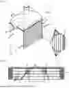
FIG. 1 shows a heat exchanger 1 according to the invention. Firstly, a longitudinal axis X is defined, extending along a length of the heat exchanger 1 corresponding to its largest dimension. Secondly, a first transverse axis Y is defined, substantially perpendicular to the longitudinal axis X and extending along a width of the heat exchanger 1. The X and Y axes form the plane XY. Finally, a third transverse axis Z is defined, substantially perpendicular to the X and Y axes, and extending along the height of the heat exchanger I. The Z axis forms the plane ZX with the X axis, and the plane ZY with the Y axis.
The heat exchanger 1 comprises several longitudinal bars 2 together defining a body 3 provided with compartments 4 defining an internal volume wherein a fluid is able to circulate. Each compartment 4 is bordered laterally along the Y axis by a longitudinal bar 2. The compartments 4 are adjacent to each other. In other words, compartments 4 are juxtaposed one on top of the other along the Z axis.
Each compartment has openings 5 through which fluid can enter and exit the interior volume.
The heat exchanger 1 has separating walls 6. A separating wall 6 is located between each compartment 4. A separating wall 6 separates the compartments 4, and therefore the corresponding interior volumes, from each other along the Z axis.
On either side of the heat exchanger 1 along the Z axis, the heat exchanger comprises an end compartment 6 located at the lower and upper ends 7. A closing wall 9 is arranged on each end compartment 7, thus closing the internal end volume and, in so doing, the heat exchanger 1.
As shown in [FIG. 1], the heat exchanger 1 comprises a fluid dispensing head 10 located at an inlet 11 of the heat exchanger 1. The dispensing head 10 has a cross-section, in the ZY plane, substantially equal to that of the body 3 of the heat exchanger 1.
The fluid thus distributed by the dispensing head 10 is distributed into the accessible compartments 4 arranged along the Z axis.
The heat exchanger 1 further comprises a collection head, not shown in the drawings, arranged opposite the dispensing head 10. The collection head collects the fluid leaving the heat exchanger 1.
The dispensing head 10 is attached to the body 3 by welding. When the welding is complete, the cooling of the weld metal causes mechanical stresses on the body 3. These mechanical stresses are commonly referred to as “material shrinkage”.
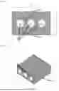
Advantageously, the heat exchanger I comprises a plurality of spacers 12. As can be seen in [FIG. 2], the spacers 12 are arranged inside the compartments 4. The spacers 12 are arranged along the openings 5. The spacers 12 maintain a distance d between two adjacent separating walls 6, when said spacers 12 are arranged between two separating walls 6. When the spacers 12 are arranged between a separating wall 6 and a closing wall 9, said spacers 12 maintain a distance d between said separating wall 6 and said closing wall 9.
The spacers 12 arranged in this way prevent deformation of the compartments 4 as a result of material shrinkage due to welding operations on the distribution or collection head 10. As the openings 5 are not deformed, operations to fill the compartments 4 with catalyst powder are possible and easy. In addition, the spacers 12 prevent the creation of compartments 4 through which the fluid cannot easily pass. This is because a deformed compartment is more difficult for the fluid to access. This would create preferential passages for the fluid and destroy the homogeneity of fluid distribution in the heat exchanger 1.
Advantageously, the spacers 12 are located in the vicinity of the dispensing head 10 and the collection head (not shown). It is in the vicinity of the dispensing head 10 and collection head that the mechanical stresses likely to deform the compartments 4 exist. The spacers 12 located there advantageously prevent deformation of the compartments 4.
Advantageously, the spacers 12 are arranged at a longitudinal end 13, along the X axis, of the body 3. The longitudinal end 13 is located at the boundary between the distribution or collection head 10 on the one hand and the body 3 on the other. It is at the longitudinal end 13 of the body that the risk of deformation is greatest. The spacers 12 thus located advantageously prevent deformation of the longitudinal ends 13 of body 3, through which the catalyst in powder form is inserted. This facilitates filling.
Advantageously, the spacers 12 are provided with perforations 14. The spacers 12 represent obstacles to the passage of fluid and/or catalyst powder. The perforations 14 are sized to allow fluid and/or catalyst powder to pass through. This reduces the impact of spacers 12 on fluid flow and/or catalyst powder filling.
Advantageously, the spacers 12 have a length L/width 1 ratio of between 0.5 and 5, preferably between 0.8 and 2. In particular, the higher the ratio, the more limited the impact of the spacers on the flow in the passage. It should also be noted that each spacer is defined by a length defined along the X axis, a width defined along the Y axis and a height defined along the Z axis (see [FIG. 4]).
According to one embodiment shown in [FIG. 2], the spacers 12 have a rectangular parallelepiped shape. In this way, each spacer 12 has a first face 15 coming into contact with a first separating wall 6 and a second face 16 coming into contact with a second separating wall 6 adjacent to the first separating wall 6 or in contact with a closing wall 9. Thus the spacers 12 have a height h measured along the Z axis substantially equal to the distance d measured along the Z axis, between two separating walls 6 or between a separating wall 6 and a closing wall 9. The spacers 12 thus sized enable the distance d to be maintained at the end of the welding operations.
In a given compartment, the spacers 12 are arranged side by side and spaced apart by a distance k measured along the Y axis, of between 5 and 30 centimeters.
Referring to [FIG. 2], spacers 12 are arranged in an end compartment 7 located beneath the closing wall 9. The end compartments 7 are located at the lower and upper ends 8, that is along the Z axis. The spacers 12 are arranged in a compartment 17 adjacent to the end compartment 7. The applicant has determined that it is effective to arrange the spacers 12 in at least two adjacent compartments to prevent the body 3 from deforming. By positioning the spacers in the end compartments 7 and in the adjacent compartment 17, deformation is avoided, as these compartments concentrate the highest mechanical stresses due to their proximity to the welds.
Advantageously, the spacers 12 are arranged one below the other, that is aligned along the Z axis as shown in [FIG. 2]. By superimposing the spacers 12 in this way, we avoid pinching the separating wall 6, which would cause it to corrugate. A staggered arrangement of the spacers 12 would result in pinching and thus undesirable corrugation of the separating wall 6.
In an embodiment not shown in the drawings, the spacers are cylindrical. Each flat face of the spacers is in contact with a closing or separating wall, while the circular face is in contact with the fluid or catalyst powder. Spacers of this shape are advantageous because they facilitate the flow of powder or fluid.
In another embodiment not shown in the drawings, the spacers are elliptical. Each flat face of the spacers is in contact with a closing or separating wall, while the ellipsoid face is in contact with the fluid or catalyst powder. Spacers of this aircraft wing shape are advantageous because they facilitate the flow of powder or fluid.
Claims
1. A heat exchanger comprising:
a body provided with a plurality of compartments including at least two end compartments, each compartment defining an internal volume inside which a fluid is capable of flowing, each compartment comprising at least one opening through which a fluid passes in order to enter or exit said internal volume,
a separating wall disposed between two adjacent compartments and separating the internal volumes from one another,
a closing wall arranged on each of said at least two end compartments and intended to close the internal end volume of said at least two end compartments, wherein the heat exchanger comprises a plurality of spacers arranged inside the compartments and along the openings, said spacers being capable of maintaining a distance between two adjacent separating walls and/or said spacers being capable of maintaining a distance between the closing wall and the separating wall adjacent to said closing wall.
2. The heat exchanger according to claim 1, further comprising at least one head for distributing the fluid into the compartments, the spacers being located in the vicinity of said at least one head.
3. The heat exchanger according to claim 2, wherein the spacers are arranged substantially at one longitudinal end of the body, said longitudinal end being located at the boundary between the at least one head and the body.
4. The heat exchanger according to claim 1, wherein the spacers are provided with at least one perforation allowing a fluid and/or powder to pass through said spacers.
5. The heat exchanger according to claim 1, wherein the spacers comprise a first face intended to come into contact with a separating wall and a second face opposite the first face, intended to come into contact with another separating wall or a closing wall.
6. The heat exchanger according to claim 1, wherein, in a single compartment, the spacers are arranged side by side and spaced apart by a distance of between 5 and 30 centimeters.
7. The heat exchanger according to claim 1, wherein the spacers are arranged in at least two compartments adjacent to one another, said spacers being substantially aligned one below the other.
8. The heat exchanger according to claim 7, wherein the spacers are arranged in each of said at least two end compartments located at a lower and upper end of said heat exchanger, and spacers are arranged in a compartment adjacent to each of said end compartments.
9. The heat exchanger according to claim 1, wherein the spacers are parallelepipedal in shape.
10. The heat exchanger according to claim 1, wherein the spacers are cylindrical in shape.
11. The heat exchanger according to claim 1, wherein the spacers are elliptical in shape.
12. The heat exchanger according to claim 1, wherein the spacers have a length/width ratio of between 0.5 and 5, preferably between 0.8 and 2.
13. A heat exchanger, comprising:
a body comprising a plurality of compartments including a first end compartment and a second end compartment, each compartment defining an internal volume inside which a fluid is capable of flowing, each compartment comprising an opening through which a fluid passes in order to enter or exit the internal volume thereof;
a plurality of separating walls, wherein each separating wall is disposed between two adjacent compartments and separates the internal volumes of the two adjacent compartments from one another;
a first closing wall arranged to close the internal volume of the first end compartment;
a second closing wall arranged to close the internal volume of the second end compartment; and
a spacer capable of maintaining a distance between two adjacent separating walls.
14. A heat exchanger, comprising:
a body comprising a plurality of compartments including a first end compartment and a second end compartment, each compartment defining an internal volume inside which a fluid is capable of flowing, each compartment comprising an opening through which a fluid passes in order to enter or exit the internal volume thereof;
a plurality of separating walls, wherein each separating wall is disposed between two adjacent compartments and separates the internal volumes of the two adjacent compartments from one another;
a first closing wall arranged to close the internal volume of the first end compartment;
a second closing wall arranged to close the internal volume of the second end compartment;
a first spacer capable of maintaining a distance between a separating wall and the first closing wall; and
a second spacer capable of maintaining a distance between a separating wall and the second closing wall.
Images & Drawings included:

Sources:
- United States Patent and Trademark Office - verify current appl. status at the USPTO↗
Recent applications in this class:
- » 20250137730 2025-05-01
HEAT EXCHANGER - » 20250052508 2025-02-13
PLATE HEAT EXCHANGER - » 20250052507 2025-02-13
HEAT-EXCHANGE DEVICE COMPRISING FLOW LIMITING DEVICES, AIR-CONDITIONING SYSTEM AND VEHICLE - » 20250027723 2025-01-23
HEAT EXCHANGER - » 20240263885 2024-08-08
Heat Exchanger for an Internal Combustion Engine - » 20240263884 2024-08-08
CONFORMAL HEAT EXCHANGER WITH TRIANGULAR OFFSET STRIP FINS - » 20240230239 2024-07-11
PLATE-TYPE HEAT EXCHANGER AND METHOD FOR FABRICATING THE SAME - » 20240230238 2024-07-11
A BRAZED PLATE HEAT EXCHANGER - » 20240200878 2024-06-20
ATTACHMENT MEANS AND HEAT TRANSFER PLATE - » 20240191948 2024-06-13
A METHOD OF MANUFACTURING AN ENERGY EXCHANGING DEVICE