GROUND PILE AND METHOD OF DRIVING THEREOF
US20250257539A1
2025-08-14
19/051,376
2025-02-12
Smart Summary: A ground pile is designed to support structures by being driven into the ground. It has a top part that connects to the structure, a middle part with a helical shape to help it move through soil, and a bottom part with a screw that helps it dig in. The screw and helical parts work together but are separate, making it easier to push into the ground. This design needs less force to drive into the soil and can navigate around rocks and debris without changing direction. Overall, it makes the process of installing piles simpler and more efficient. 🚀 TL;DR
Abstract:
A ground pile comprises a body having an upper portion configured to receive a pile head for securing at least a portion of a structure thereto, a middle portion having a helical member secured thereto and extending radially therefrom, and a bottom portion having at least one wall oriented inwardly and a screw member secured thereto, an outer diameter of the screw member being between 1/16 of an inch and a maximum radial distance of the wall of the middle portion from the longitudinal axis. The screw member and the helical member are separate and have substantially the same pitch. The ground pile requires less torque for being driven into the ground and displaces rocks, debris, and other obstacles easily, maintaining the driving direction.
Assignee:
- GOLIATHTECH INC. 9 🇨🇦 Magog, Canada
Applicant:
Interested in similar patents?
Get notified when new applications in this technology area are published.
Classification:
E02D5/56 » CPC main
Bulkheads, piles, or other structural elements specially adapted to foundation engineering; Piles Screw piles
E02D7/22 » CPC further
Methods or apparatus for placing sheet pile bulkheads, piles, mouldpipes, or other moulds Placing by screwing down
Description
RELATED APPLICATIONS
The present application claims priority from U.S. Provisional Patent Application No. 63/678,878 filed Aug. 2, 2024, U.S. Provisional Patent Application No. 63/566,021 filed Mar. 15, 2024, and U.S. Provisional Patent Application No. 63/553,468 filed Feb. 14, 2024, each of which are incorporated herein by reference in their entirety.
TECHNICAL FIELD
The present disclosure relates to construction piles, and more precisely to ground piles.
BACKGROUND
The use of piles is an alternative to the use of concrete foundations in different residential, commercial, recreational, or agricultural applications. Piles are typically installed deep into the ground to support both buildings, such as homes, and accessory structures such as decks, sun rooms, car ports and the like.
A pile generally includes an elongated body and may have members added thereto for providing stability against lateral or angular displacement of the installed pile. The pile is driven into the ground and a structure may then be secured to the pile.
Conventional helical piles generally comprise a cylindrical body having an angled bottom to form a blade, and a helix for providing resistance to displacement of the pile once installed. Driving helical piles can be time-consuming due to soil resistance and deviation of the pile from the intended driving direction.
Ground screws have been proposed in some jurisdictions as an alternative foundation component. In some cases they can be faster to install. However, ground screws are not compliant with current North American building requirements. In particular, ground screws do not provide the requisite resistance to angular displacement, pulling or subsidence.
There is accordingly a need for improved piles to address at least some of the disadvantages of existing piles.
SUMMARY
According to a broad aspect, the present disclosure provides a ground pile comprising a body having an upper portion, a middle portion and a bottom portion, each portion having at least one wall, the body defining a longitudinal axis extending between the upper portion and the bottom portion, the upper portion being configured to receive a pile head for securing at least a portion of a structure thereto, the at least one wall of the bottom portion being oriented inwardly towards the longitudinal axis and defining a tip at a bottom end of the bottom portion, a helical member secured to the middle portion and extending radially therefrom, a screw member secured to and abutting the bottom portion and extending radially therefrom, an outer diameter of the screw member being between 1/16 of an inch and a maximum radial distance of the wall of the middle portion from the longitudinal axis, the screw member and the helical member being separate; and the screw member having a first pitch, the helical member having a second pitch, and the first pitch and the second pitch being substantially equivalent.
In embodiments, the upper portion is further configured to receive a driving attachment, the driving attachment comprising an engagement portion configured to matingly engage a drive motor for driving the ground pile into the soil. In embodiments, the driving attachment is removable. In embodiments, the pile head is configured to receive a tool for urging rotation of the pile head about the longitudinal axis. In embodiments, the upper portion and the middle portion are substantially cylindrical, and the bottom portion is substantially conical. In embodiments, at least one of the helical member and the screw member is removable or designed to be assembled on site.
In embodiments, the helical member comprises a sleeve portion engageable about the middle portion, a twisted member secured to the sleeve portion and defining a helix, and fastening apparatus for fastening the sleeve portion to the middle portion. In embodiments, the screw member comprises a sleeve portion engageable about the bottom portion, a twisted member secured to the sleeve portion and defining a screw thread, and fastening apparatus for fastening the sleeve portion to the bottom portion.
In embodiments, the structure is one of a fence, a beam, a deck, a sun room, a cart port, a mobile home, a manufactured home, a prefabricated home and a cabin.
In embodiments, the top portion defines an aperture configured to receive a complementary driving member therethrough for driving the ground pile into the ground. In embodiments, the aperture is substantially square.
In embodiments, a kit comprises the ground pile as described above and one or more adapters the adapters comprising the driving member and configured to be operatively connected to a driving motor.
According to a broad aspect, the present disclosure provides a ground pile comprising a body having an upper portion, a middle portion and a bottom portion, each portion having at least one wall, the body defining a longitudinal axis extending between the upper portion and the bottom portion, the upper portion being configured to receive attachment apparatus for securing a structure thereto, the bottom portion being substantially conical and having a tip pointing in a longitudinal direction opposite the upper portion, a helical member secured to the middle portion and extending radially therefrom, the helical member having a constant outer diameter; the bottom portion having a screw thread extending therefrom, an outer diameter of the screw thread being between 1/16 of an inch and a maximum radial distance of the wall of the middle portion from the longitudinal axis, a pitch of the screw thread and a pitch of the helical member being substantially equivalent.
According to a broad aspect, the present disclosure provides a method of driving a ground pile, comprising engaging a ground pile head with a complementary engagement apparatus operatively connected to a drive motor, rotating the ground pile to drive a screw portion of the ground pile into the ground, rotating the ground pile to drive a helical member provided on the ground pile into the ground, and disconnecting the pile head from the drive motor.
In embodiments, the method further comprises securing the helical member to the ground pile. In embodiments, the method further comprises securing a screw member to the screw portion of the ground pile. In embodiments, the method further comprises securing the pile head to the complementary engagement apparatus.
BRIEF DESCRIPTION OF THE DRAWINGS
Having thus generally described the nature of the invention, reference will now be made to the accompanying drawings, showing by way of illustration example embodiments thereof.
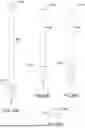
FIG. 1 is a side view of a ground pile according to an embodiment.
FIG. 2 is a cross-section of the upper portion of the ground pile of FIG. 1.
FIGS. 3A and 3B are side views of the screw member and the helical member of the ground pile of FIG. 1.
FIG. 4 is a side view of a detail of the ground pile of FIG. 1.
FIG. 5 is a side view of the bottom portion of the ground pile of FIG. 1, with the screw member removed.
FIGS. 6A to 6E are perspective views of ground piles having different pile heads according to various embodiments.
FIG. 7 is a side view of a detail of a ground pile according to another embodiment having a contiguous flight from a helical blade to a screw member.
FIG. 8 is a flow diagram of a method of driving a ground pile according to an embodiment.
FIGS. 9A to 9C are top, side, and isometric views, respectively, of the screw member of FIG. 1.
FIGS. 10A to 10D are ground piles according to embodiments showing weep holes therein.
FIGS. 11A and 11B are ground piles according to embodiments before formation of a tapered tip.
FIGS. 12A and 12B are ground piles according to embodiments after formation of a tapered tip.
FIGS. 13A and 13B are side and top views of a helical blade according to embodiments.
FIGS. 14A to 27C show exemplary pile heads and components therefor according to embodiments.
FIGS. 28A to 39B show exemplary ground piles according to embodiments.
FIGS. 40A to 41C show details of exemplary ground piles configured to receive a driving adapter according to embodiments.
FIGS. 42A and 42B show an assembled ground pile according to an embodiment.
FIGS. 43A to 43D illustrate a further embodiment of the ground pile without a head assembly installed and having a segmented screw member.
FIGS. 44A to 44D illustrate the further embodiment as shown in FIG. 43D and including a multi-use plate integrated as a head assembly.
FIGS. 45A to 45C illustrate the further embodiment as shown in FIG. 43D and including a tubular head assembly.
FIGS. 46A to 46C illustrate the multi-use plate as embodied in FIG. 44D.
FIGS. 47A to 47C illustrate the tubular head assembly as embodied in FIG. 45C.
FIGS. 48A to 48C illustrate a top section of the tubular head assembly as embodied in FIG. 45C.
FIGS. 49A through 49C illustrate a bottom section of the tubular head assembly as embodied in FIG. 45C.
FIGS. 50A and 50B illustrate the helical blade as embodied in FIG. 43C.
FIGS. 51A to 51D illustrate the pile tube as embodied in FIG. 43C.
FIGS. 52A to 52E illustrate the segmented screw member as embodied in FIG. 44C.
FIGS. 53A to 53E illustrate a top section of the segmented screw member as embodied in FIG. 44C.
FIGS. 54A to 55B illustrate a bottom section of the segmented screw member as embodied in FIG. 44C.
FIGS. 56 to 59 illustrate perspective views of the segmented screw member in accordance with the further embodiment.
DETAILED DESCRIPTION
Throughout the present specification, the term “screw” and its variations generally denotes a thread pattern where the outside diameter of the thread decreases or increases between two opposite ends of the pattern.
Throughout the present specification, the term “helix” and its variations generally denotes a thread pattern that has a substantially unvaried thread diameter between two opposing ends of the pattern.
Throughout the present specification, the terms “revolution” and “flight” are used interchangeably to define portions of a helix or of a screw relative to revolutions about the longitudinal axis.
Referring now to FIG. 1, a ground pile 100 is presented. The pile 100 comprises a body 110 having an upper portion 111, configured to have a building, a structure or a component thereof secured thereto, an inwardly angled bottom portion 113 and a main portion 112 extending therebetween. The pile 100 generally has a cylindrical shape defined by a wall having an outer face 102 and an inner face 103 (see FIG. 2 as cross section of the area defined by 111 and 112). In the illustrated embodiment, the wall 101 has a thickness of about 0.25 inches. The thickness of the wall 101 may be less, for example as little as about 1/16 of an inch, or greater, such as up to about 1 inch, depending on the intended load and on the soil characteristics of the intended use location. The upper portion comprises a pile head 150. It is understood that the pile head 150 may be removable. The pile head 150 may comprise a nut 151, for example a hexagonal nut for engaging a complementary socket on a drive motor (not shown).
The structure to be supported (not shown) by the ground pile 100 may be any of a fence, a beam, a deck, a sun room, a cart port, a mobile home, a manufactured home, a prefabricated home, a cabin, and other structures suitable for being supported on ground piles as disclosed herein.
In one embodiment, the body 110 is made of galvanized steel. Galvanized steel provides the advantages of being weather resistant and is less susceptible to corrosion and yet has sufficient mechanical strength to support heavy loads such as those associated with buildings and accessory structures. It is however contemplated that the body 110 may be made of any other material that is adapted to resist weather conditions and mechanical stresses and strains caused by the installation of the ground pile 100 and/or the loads associated with the structures supported by the ground pile 100.
In one embodiment, the body 110 is substantially hollow and the wall 101 defines a cavity (not shown) in the body 110. In other embodiments, materials may be added to the cavity to improve any one or more of frost resistance, moisture resistance, weight and the general strength of the pile 100. Such materials may include but are not limited to polymers, polymer foams, sand, stone screenings, concrete, gravel and others. The outer face 102 may be provided with protective apparatus (not shown), such as a protective layer, a coating or a sleeve for protecting the body 110 against the elements, corrosion, mechanical wear and other interferences. The protective layer or coating may comprise polymers, resins, silicone, carbon fibre, paints, tar, bitumen, plastics, antibacterials, anticorrosives, antioxidants, and other protective components and compositions.
Secured to the inwardly angled bottom portion that is tapered to a point as shown is a screw member 120. The screw member 120 provides a screw thread for guiding the bottom portion 113 downwardly when the pile 100 is rotated. The screw member 120 is welded to the bottom portion 113, however it is understood that the screw member 120 may be removable, or configured to be attached on site, and may be otherwise secured to the bottom portion 113. For example, a removable screw member 120 may be replaced due to excessive wear or due to impacting an object such as a rock, a pipe, or other objects during driving of the pile 100, without having to replace the entirety of the pile 100.
In the illustrated embodiment, the screw member 120 has a pitch of about 3 inches, a thread depth of about ⅜ inches and a thickness of about 1/16 inches. In this configuration, the screw member 120 minimizes material use during the manufacture of the ground pile 100. It is understood that other configurations are possible. For example, a greater thickness, up to about ½ inch, may be used in more difficult soils, such as rockier, denser, or cold and/or frozen soils. Thread depth may range from about ¼ into to about ⅞ inch, and may be chosen depending on the characteristics of the soil in which the pile 100 may be used. For example, greater thread depth may provide easier ground penetration in soils having a high content of small rocks or debris.
In the illustrated embodiment, the outer edge of the screw member 120 is substantially flat. In embodiments, the outer edge of the screw member 120 may be beveled, sharpened, or provided with surface modifications such as teeth, bumps, or abrasive additives to increase the penetrating power of the ground pile 100.
Secured to the main portion 112 proximate the bottom portion 113 is a helical member 130. In the illustrated embodiment, the helical member 130 has an outside diameter of about 6 inches, the outer face 102 of the main portion 112 having a diameter of about 3 inches. Accordingly, the helical member 130 extends into the soil around the pile 100 and provides resistance to movement of the pile 100 once the pile 100 is installed. It is understood that alternate diameters may be used for the helical member depending on the characteristics of the soil.
It should be readily apparent therefore that the screw member 120 provides initial penetration into the soil in a bore-like manner while the helical member 130 provides retention of the ground pile 100 in an anchoring manner that is resistant to vertical movement.
The configuration of the pile 100 and of the helical member 130 may be adapted to the characteristics of the ground in which the pile 100 is to be used. For instance, the length of the body 111,112 may be adapted such that the helical member 130 is positioned below a ground freezing zone when the ground pile 100 is installed. In other examples, the helical member may be secured to the body 111,112 at a longitudinal distance from the bottom portion 113 to account for a layer of soil unsuitable or inconvenient for anchoring or securing a ground pile. Thus, the helical member may be located at any suitable portion along the length of the body 111,112. It is also contemplated that the length, diameter, and thickness of the pile body 111,112 may be selected according to its usage.
Referring to FIG. 3A, in the illustrated embodiment, the screw member 120 has a maximum outer diameter that substantially does not exceed the diameter of the outer face 102 of the lower body portion 112. As seen in FIG. 4, a thread discontinuity is also present between the top end of the screw member 120 and the bottom end of the helical member 130. This discontinuity may also be termed a “flight transition.” The helical member 130 and the screw member 120 are thus separate.
The screw member 120 assists in driving the pile 100 downwards, by enabling the bottom end 113 of the pile 100 to generate a downward force when the pile 100 is rotated. However, the screw member 120 leaves soil located more than about 1.5 inches away from the longitudinal axis 104 (as delineated in FIGS. 4 and 7) in a substantially undisturbed and relatively virgin state. The helical member 130 therefore engages undisturbed and stable soil for providing resistance to upward, downward, and angular movement of the pile 100, thus satisfying axial capacity requirements for construction purposes and anchoring the pile 100 in place within the ground.
The pitch of the screw member 120 substantially corresponds to the pitch of the helical member 130. Each component of the pile 100 is thus driven into the ground at substantially the same rate. Such a configuration reduces both resistance to ground penetration by the helical member 130 and excessive soil disturbance by the screw member 120.
As shown in FIG. 3B, the helical member 130 defines a one-revolution helix about the longitudinal axis 104. It is understood that other configurations, such as additional revolutions, i.e. a longer helix may be used. A plurality of helical members such as helical member 130 may also be used, being secured to the ground pile 100 at a plurality of points along the length of the ground pile. For example, a plurality of helical members may be used when additional resistance is required of the ground pile 100, such as in softer soils, with a higher intended load, or in the expectation of stresses on the structure to be supported by the ground pile 100 such as high winds, floods, and others.
Referring to FIG. 5, the bottom portion 113 is angled inwardly in a tapered manner and the outer surface of the bottom portion 113 defines an angle with respect to the longitudinal axis 104. In the illustrated embodiment, the bottom portion has a length of about 12 inches and a maximum diameter of about 3 inches, the outer surface of the bottom portion 113 defining an angle of about 7 degrees with respect to the longitudinal axis 104 and forming an approximately 14-degree point at the tip of the bottom portion 113. It is understood that other angles, providing for a sharper or for a duller tip of the bottom portion 113 may be used depending on soil conditions and other factors.
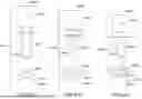
Referring to FIGS. 6A to 6E, there are shown various embodiments of a ground pile 100a through 100e that include a pile body having an upper portion with a corresponding head assembly 150a through 150e secured thereto, a lower portion having a helical member 130, and a bottom portion including a screw member as previously described hereinabove. Each head assembly 150a through 150e is configured to be secured to, or to otherwise engage a driving mechanism for rotating and driving the given pile 100a through 100e into the ground. The given head assembly 150a through 150e may be attached to the driving mechanism using screws, bolts, or other suitable attachments. In embodiments, the head assembly may include a shape defining a socket for a driving mechanism to engage with. In other examples, the head assembly may have a shape, for example a polygonal shape, for example square or hexagonal, configured to engage a complementary socket on the driving mechanism. In such examples, installation of the given ground pile 100a through 100e is simplified by enabling a rapid connection and disconnection of the ground pile 100 with a driving mechanism.
The head assembly 150a through 150e may be secured to the ground pile using any appropriate securing apparatus. In the illustrated embodiment, each head assembly 150a through 150e is welded to the pile body. Welding may provide lower production costs and a more uniform distribution of torque when the rotation torque is transmitted from the driving mechanism, through the head assembly to the pile body. Other attachment elements are also possible. For example, a head assembly may be attached to the pile body using brackets, which may be secured to the outer face 102 or the inner face 103 of the pile body wall, or both. The head assembly may be secured to the pile body by defining a sleeve (not shown) into which the upper end of the pile body may be received, or vice-versa, the upper end of the pile body may receive the sleeve inside the cavity defined by the wall of the pile body. The sleeve and the upper end of the pile body, in such an example, may have complementary and radially opposed bores or holes (such as 301a and 301b in FIGS. 10B and 10D), each configured for receiving a rigid member including but not limited to a bolt, a screw, a rivet, or other apparatus for linking the sleeve and the upper portion of the pile body together. It is understood that the shape of the sleeve is complementary to the shape of the pile body.
In configurations whereby the head assembly is not welded to the pile body, it should be readily understood that the head assembly may be removable. In such embodiments, the ground pile may be configured to receive different attachments as the head assembly. For example, one attachment may be a driving attachment, such as a quick connect or quick-disconnect attachment having a complementary shape to engagement apparatus on the driving mechanism and which are shown and described hereinbelow with regard to FIGS. 41A through 42C. Once the ground pile is installed in place within the ground, the driving attachment may be removed and an attachment suitable for securing a structure thereto is provided, such as a round head, a U-shaped head, a V-shaped head, or other heads suitable for the intended use.
The ground pile may be configured to be extendable. In such examples, the portions 111,112 may be configured to enable securing an additional member, having substantially the same outer diameter as the pile body, to the middle portion or to the upper portion of the ground pile 100, and to secure the given head assembly, simply referred to also as the head, (i.e., 150a through 150e as seen in FIGS. 6A to 6E) or other apparatus for engaging the driving mechanism to the additional member for driving the ground pile 100 further into the ground. In an example, the head may have a threaded sleeve and the upper portion 111 may have a complementary thread on the inner face 103, the thread direction being the same as the rotation direction of the ground pile 100. To extend the ground pile 100, the head is removed and an additional member having a thread complementary to the thread in the upper portion is screwed into the upper portion, and the head is attached to or secured to the upper portion of the additional member. Other apparatus of engaging the additional member are possible, including but not limited to latching, bolting, and/or providing a bayonet mount. It is understood that the engagement resists movement of the additional member with respect to the upper portion 111 when the ground pile 110 so extended is rotated when driving.
Referring now to FIG. 7, a ground pile according to an embodiment comprises a variable-width screw member extending in a contiguous flight 160 from helical blade in the middle portion 112 to substantially the tip of the bottom portion 113. FIGS. 9A through 9C show the screw member 120 in top, side, and perspective views, respectively. The outer diameter of the member 120 at the middle portion 112 is about 6 inches and the screw member 120 maintains a constant outer diameter for at least one revolution about the longitudinal axis 104. As the screw member 120 extends downwards, the outer diameter decreases. The decrease may be gradual, for example decreasing from about 6 inches to about 3 inches over the course of about ¼ to about 2 revolutions about the longitudinal axis 104. The decrease could be discrete, for example by providing an outer diameter of about 6 inches for the first revolution about the longitudinal axis, and of about 3 inches thereafter. It is understood that the width of the screw member 120 may accordingly change, for example having a width of about 1.5 inches for the first revolution, a width of as little as 1/16 inches at the widest end of the bottom portion 113, and a width of about 1/16 inches to about 1 inch at the tip of the bottom portion 113. The helical blade may have a pitch of 3 inches, a constant outer diameter of 6.5 inches and an inner diameter is 3 inches, substantially matching a starting outer diameter of the screw member as may be seen in FIG. 4.
Referring to FIG. 8, a method 200 of driving a ground pile into the ground is also presented. The method comprises engaging a ground pile head with complementary engagement apparatus (shown and described later with reference to FIGS. 40A to 41C) operatively connected to a drive motor (201), rotating the ground pile to drive a screw portion of the ground pile into the ground (202), rotating the ground pile to drive a helical member provided on the ground pile into the ground (203), and disconnecting the pile head from the drive motor (204). The present method reduces the torque and force required to drive a ground pile into the ground while maintaining the pile's axial capacity. Furthermore, the driving of the helical member allows for an evaluation of the pile's axial capacity during installation of the ground pile, rather than following the driving. Accordingly, validation times and downtime due to mis-installed or insufficiently anchored ground piles are reduced.
The method may further comprise securing the pile head to the drive motor, in addition to engaging the drive motor. For example, a hexagonal pile head may engage a complementary hexagonal socket on a drive motor attachment, and further securing apparatus such as fasteners, brackets or latches may be engaged to further secure the head to the motor. When either or both of the screw member and the helical member are provided separately or are detachable, the method further comprises securing the screw member or the helical member to the ground pile.
Referring to FIGS. 10A to 10D, ground piles 300 according to embodiments are illustrated showing weep holes therein including lower hole 302, and upper hole 303 each located in the tapered portion of the pile 300. Apertures 301a and 301b are provided and which may provide a through bore into which a tool (not shown) may be used to engage the pile 300 for rotation. The length of the pile 300 is shown with a discontinuity to indicate that the pile of course may be provided in any desired length.
Referring to FIGS. 11A and 11B, the ground pile is shown according to embodiments before formation of a tapered tip 300′ (seen in FIG. 12B) where FIGS. 12A and 12B illustrate the ground pile 300 according to embodiments after formation of the tapered tip 300′.
Referring to FIGS. 13A and 13B, there are shown side and top views of a helical blade 130 detached from the pile versus such as seen according to embodiments including FIG. 1.
Referring to FIGS. 14A to 27C, there are illustrated exemplary pile heads and components therefor according to embodiments for use with ground piles according to embodiments of the present disclosure. These may comprise pile heads adapted to the intended use and driving method. The pile head may have different shapes. For example, a ground pile may comprise a head defining with a square or hexagonal aperture for inserting a driving adapter therein, such as a complementary square or hexagonal head of a drive motor.
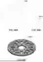
In particular, in FIGS. 14A and 14B, a flat, round head 405 with a square aperture 406 may be provided with one or more openings (e.g., eight oblong openings shown equally distributed) that may be used for attachment of the head to an element supported by the head. Further, for example, exemplary U-shaped pile heads 1500, 1600, or 1700 defining, respectively, a circular aperture 1501, rectangular aperture 1601, or hexagonal aperture 1701, may be provided. Likewise, one or more opening 1503, 1603, or 1703 may be provided for attachment of the given head to an element supported by the head. Further, the given U-shaped head may be configured to be secured to a flat pile head using acceptable securing apparatus including but not limited to bolts, screws, and other fastening and securing apparatus.
It should be understood that the any particular head may be welded to the top portion of the pile or secured thereto. In embodiments, the ground pile may comprise a flat pile head such as those seen in FIGS. 18A through 24C, defining an aperture, and configured to receive a head or a frame thereon. For example, the U-shaped head of FIG. 15 may be configured to be secured to a flat pile head using acceptable securing apparatus including but not limited to bolts, screws, and other fastening and securing apparatus. It is understood that the apertures defined by the U-shaped head and the flat head are complementary.
In embodiments, the aperture has other shapes useful for driving the ground pile into the ground. For example, as shown in FIG. 18A, a flat hexagonal ground pile head 1800 may define a circular aperture 1801 or, as shown in FIG. 20A, a square ground pile head 1900 may define a hexagonal aperture 1901 for engaging the ground pile with a driving mechanism. Likewise, the pile head 2200 may be hexagonal with a hexagonal aperture 2201 as shown in FIG. 24A. The pile head may have other shapes and configurations to be understood as within the intended scope of the present disclosure.
It should also be readily apparent that the size of the aperture(s) may vary and the shown dimensions are exemplary only. For example, the aperture may be about 2 inches across. In other examples, as shown in FIGS. 19A and 22A, the pile head may comprise a nut 1803, 2003 or a protrusion for engaging a complementary adapter or drive motor component for driving the ground pile into the ground.
As mentioned, an exemplary pile head is configured to receive one or more different components secured thereto. Such an adaptable pile head comprises a plurality of apertures for fastening components therethrough, For example, as shown in FIG. 27A, the pile head may be flat for driving the ground pile into the ground. Once the ground pile is driven into the ground, L-shaped brackets 2300 (seen in FIGS. 25A to 25D) or extensions may be fastened to the pile head using nuts and bolts, thereby enabling the ground pile to receive a beam through a space between the two or more brackets. It is understood that the size, position, and distance between the brackets may be adapted to the size and direction of a beam of a structure. Accordingly, a building or other structure supported on the ground pile may be modified, moved, expanded, or otherwise changed without needing to remove or re-install the ground pile. It is contemplated that an arrangement of ground piles having been driven into the ground may be used to support a first structure, the first structure may be moved or re-configured, and the arrangement of ground piles may be adapted to receive the new or modified structure simply by adapting the configuration of the brackets as described above.
The adaptable pile head as described above may be configured to receive a driving adapter or driving component, for example as shown in FIG. 45. The driving component, shown as a hexagonal plate with a hexagonal protrusion or nut, is secured to the pile head using four bolts. After the ground pile is driven into the ground, the plate may be removed, and other components such as a U-shaped head (for example in FIGS. 15-17), one or more brackets (shown for example in FIG. 25) or other components may be secured to the pile head. It is understood that a structure may be supported on the pile head directly, and secured thereto for example by bolts threaded through one or more of the apertures defined by the pile head.
The ground pile according to the present disclosure may comprise components adapted for producing the ground pile and for driving it into the ground. FIGS. 28A to 39B show exemplary ground piles according to embodiments. The ground pile may be adapted for optimizing a galvanization process. For example, when the ground pile is galvanized steel, the ground pile may be galvanized using a hot-dip process, requiring efficient discharge of fluid from the pile body after the galvanization is complete. According to some embodiments, for example as shown in FIG. 5 or 12B, the bottom portion of the ground pile may not define apertures, and the ground pile is accordingly emptied of fluid via the top portion after galvanization. In other embodiments, as shown in FIGS. 10B and 10D, the bottom portion may define one or more apertures, such as the apertures 302, 303, which apertures may be on opposite sides of the ground pile and at different longitudinal distances from the tip of the bottom portion. Following galvanization, fluid may drain out of the ground pile rapidly through the apertures and/or through the top portion, the apertures and the top portion providing air flow to prevent vacuum resistance to draining of the ground pile body. Accordingly, the ground pile may be galvanized more efficiently and more quickly.
With reference to FIGS. 28A to 28D, the ground pile 3000 may comprise apertures. FIG. 28B includes a close-up C indicative of FIG. 28C along with cross-section D-D indicative of FIG. 28D. FIGS. 29A to 29D are substantially identical to FIGS. 28A to 28D except for the addition of the helical blade 4001 thereby attached to the pile 4000. FIG. 29B includes a close-up C indicative of the detail shown in FIG. 29C where the screw member 4002 is visible. Following galvanization, the ground pile 3000 may be emptied efficiently through the bottom apertures 3002 or through the top portion. In particular, apertures in the top portion provide an air inlet or an outlet for galvanization fluid even when a remainder of the top portion is closed or obstructed, for example by a preinstalled pile head defining no apertures through which the ground pile may empty. Accordingly, a ground pile may be fabricated having any pile head configuration and galvanized as a whole, reducing overall costs and reducing the need to galvanize the ground pile and the pile head separately.
Referring now to FIGS. 30A through 39C, the ground pile is shown in a variety of exemplary configurations with head assemblies of various shapes. FIGS. 30A to 30D shows a pile 4000 having a head assembly 4004 like that shown in FIG. 18A. FIGS. 31A to 31D shows the pile 4000 having a head assembly 4005 like that shown in FIG. 19A. FIGS. 32A to 32D shows the pile 4000 having a head assembly 4006 like that shown in FIG. 17A, while FIGS. 33A to 33D shows the pile 4000 having a head assembly 4007 like that shown in FIG. 17A where the head is relatively wide, while FIGS. 34A to 34D shows the pile 4000 having a head assembly 4008 like that shown in FIG. 17A where the head is relatively short. FIGS. 35A to 35D shows the pile 4000 having a head assembly 4009 like that shown in FIG. 20A. FIGS. 36A to 36D shows the pile 4000 having a head assembly 4010 similar to that shown in FIG. 22A. FIGS. 37A to 37D shows the pile 4000 having a head assembly 4011 like that shown in FIG. 24A. FIGS. 38A to 38C shows the pile 4000 having a head assembly 5000 similar to that shown in FIG. 14A with accompanying L-brackets similar to that of FIG. 25A coupled thereto. FIGS. 39A to 39C shows the pile 4000 having a head assembly 5000 similar to that shown in FIG. 14A with additional head assembly 2400 having nut 2403 like FIG. 27A coupled thereto. Accordingly, it should be readily apparent that may different variations of head assemblies may be produced by way of the present disclosure without straying from the intended scope of the invention.
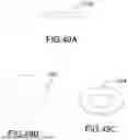
As previously mentioned, the ground pile may be configured to receive a driving adapter. FIGS. 40A to 41C show details of exemplary ground piles configured to receive a driving adapter according to the embodiments. As shown in FIG. 40A, configuration 6001 illustrates the ground pile 4000 comprises a square pile head 6013 having a square central aperture 6020 whereby a driving adapter 7000 includes an elongated tongue 7002 having a square cross section which fits into the square central aperture 6020 and shown partially inserted. In configuration 6003 of FIG. 40C, the elongated tongue 7002 is shown fully inserted into the square central aperture 6020 due to the relative width of U-shaped head 6012. Likewise, the configuration 6002 of FIG. 40B shows a narrow version of the head 6011. In each configuration, the driving adapter 7000 may be attached to a hydraulic mechanism (not shown) and locked in rotation therewith via the through-bore 7001. Each of FIGS. 41C through 41C likewise illustrate similar configuration 6004 through 6006 though with regard to flat shaped heads 6013, 6014, and 6015.
Accordingly, protruding portions, such as a U-shaped head, and a square aperture may be provided in the top portion for driving the pile. The driving adapter comprises a driving portion complementary to the given aperture defined by the ground pile and configured to be received therein, and a head portion configured to engage a driving mechanism or to be otherwise attached to a driving mechanism for exerting a driving force on the ground pile. The cross-section of the driver and the corresponding aperture may be any suitable shape. The length of the driving adapter's portion allows the adapter to be received in the aperture regardless of the height of the U-shaped head. In embodiments, for example as shown and previously described with regard to FIG. 40C, the U-shaped head is wide enough to receive the adapter head portion, and accordingly the adapter may have substantially the entire length of the drive portion received into the body of the ground pile. Where the pile head is flat, as shown and previously described in any of FIGS. 41A to 41C, the adapter's driving portion is substantially entirely received into the ground pile. It is understood that, in such embodiments, the adapter's driving portion may be shorter. In embodiments, a plurality of adapters may be provided as a kit for mounting an appropriate adapter to the driving mechanism whereby the kit may include one or more adapter(s) and one or more corresponding pile head(s).
As shown in FIGS. 40A to 41C, the adapter's driving portion may comprise apertures, notches, or holes configured to be radially level with one or more apertures defined in the top portion of the ground pile. In embodiments, the adapter's driving portion defines a through axial aperture complementary to two apertures in the top portion of the pile. Securing apparatus such as bolts, screws, and members configured to thread between a first aperture in the body of the ground pile, the through axial aperture in the adapter driving portion, and a second aperture in the body of the ground pile opposite the first aperture may be provided to additionally secure the adapter to the ground pile. It is understood that the adapter may drive the ground pile without being additionally secured. The adapter may be additionally secured to the ground pile to reduce or prevent vertical movement of the adapter and/or to improve a force distribution between the adapter, the pile head, and the pile body.
Referring to FIGS. 42A and 42B, an exemplary ground pile 4000 may be configured to have a driving adapter, such as a protrusion 2404 on a plate 2400 adapted to be mounted or secured to the top portion 5000 of the ground pile, and to further comprise a pile head 6016 on a member 2405 extending from the top portion of the pile head. In the illustrated embodiment, the ground pile 4000 is configured to be driven into the ground using a protrusion 2404 or nut provided on a plate 2400 secured to the top portion 5000 of the pile body. The U-shaped bracket as pile head 6016 may be secured to the ground pile 4000 at a distance therefrom. It is understood that the U-shaped bracket 6016 and the plate 2400 may be formed together, and provided onto the ground pile prior to the ground pile being driven into the ground. Accordingly, the bracket 6016 may be configured to be operatively connected to a driving motor (not shown) and to transfer torque and/or a rotational force to the ground pile to cause a rotation thereof.
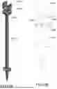
A further embodiment in accordance with the present invention will now be described in detail with regard to FIG. 43A through FIG. 59. With regard to FIGS. 43A through 43D, there is illustrated a further embodiment including a ground pile with a screw member 504. For the sake of illustrative clarity, the ground pile and screw member 504, while shown together, do not include a head assembly. Indeed, the head assembly may be provided in a variety of forms as previously elucidated and as will be further described hereinbelow. The ground pile includes a tubular section 501 to which the screw member 504 is attached at a lower end thereof and below a helical blade 505. The helical blade 505 is attached by welding to the tubular section 501. The tubular section 501 may include apertures 502, 503 as shown which may facilitate attachment of a head assembly by way of pins, thru-bolts, screws, or the like (not shown) and also aid in the galvanization process as previously described. As seen by broken lines of FIGS. 50a and 50b, the tubular section 501 may be fabricated in any length. It should be noted that the width 511 of the tubular section is not less than the largest diameter of the screw member 504. In other words, the outer periphery of the screw member 504 including a corresponding screw blade (or screw thread) 507 of the screw member does not exceed the outer periphery of the tubular section. In this manner, the downward path of the ground pile when driven into the ground disturbs only enough soil material required for the presence of the tubular member. This allows for the maximum amount of exposure of the surface 505 of the helical blade 513 to substantially undisturbed native soil material. This effectively maximizes the vertical stability of the ground pile upon full installation in the ground.
As shown in FIG. 43c, it should also be noted that the screw member includes an interface 508 with the tubular section. The interface includes an alignment notch 506. The alignment notch enables consistent assembly of the screw member with the tubular section to ensure contiguous flight transition between the helical blade and the screw blade. It should therefore also be understood that the screw member is a separate and distinct part relative to the tubular section. This differs from earlier described embodiments wherein the portion of the ground pile forming the screw member was actually a tapered end of the tubular section. In such earlier described embodiments, it should be noted that while tapering the tubular section to form the screw section utilizes the same length of tube to create the screw member and therefore efficiently utilizes the same material, the trade off in consistency of tapered shaping (e.g., by compressing a rotating end of the tubular section) may introduce irregularities into the manufacturing process. The embodiment as seen in FIG. 43A avoids any vagaries of manufacturing the tapered end from the tubular section itself. Rather, the embodiment as shown in FIG. 43A provides a screw member that is preferably cast with integrated screw blades as will be described further hereinbelow. Such casting material may include casting using a similar or identical metal as the tubular section. Alternatively, it is well within the intended scope of the present disclosure that the screw member be manufactured from differing material than the tube section such as, but not limited to, more cost effective metals or suitably durable polymers based upon the given implementation. For example, a polymeric material with biodegradability characteristics may be warranted for one particular environment while a high quality metal may be warranted in a different environment. It should of course be understood that site requirements such as soil content may contribute to the factors dictating the given material from which the screw member is fabricated. As well, the screw member being manufactured in one or more sections may dictate that differing materials may be used for different sections of the screw member without straying from the intended scope of the invention.
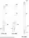
Similar to earlier described embodiments, the further embodiments as shown in may include a head assembly. The head assembly may be provided in a variety of forms. Here, FIGS. 44A to 44D illustrate the further embodiment as shown in FIG. 43A though now including a multi-use plate 5000 integrated as a head assembly. The multi-use plate 5000 is integrated by welding to the tubular section 501. Likewise, the head assembly may be provided in an alternative manner such as seen in FIGS. 45A through 45C which illustrate the further embodiment including a tubular head assembly 5001. The tubular head assembly 5001 includes apertures to secure the tubular head assembly via a locking device—e.g., pin, thru-bolt, screw, or the like (not shown). Likewise, one or more apertures may be provided to enable attachment to a drive mechanism (not shown) via a similar locking device.
With reference to FIGS. 46A through 46C, the multi-use plate 5000 as embodied in FIG. 44D will now be shown and described in detail. The multi-use plate 5000 includes a series of radially distributed apertures. Each aperture is an oblong opening through the thickness of the multi-use plate 5000. The apertures are generally arranged with their greatest length oriented in a radial direction. The shape and orientation of the apertures provides optimal usability these oblong openings for subsequent attachment of additional bolted on parts which may include, without limitation, additional head assembly fastener elements (not shown) which may be customized to any given setting in which the ground pile may be implemented. The apertures therefore enable multiple and varied usage while still providing a head assembly with sufficient structurally integrity to withstand rotational torque experienced during installation and de-installation. The multi-use plate thus provides uniform distribution of torque when integrated with the tubular section. In the embodiment as shown, the multi-use plate 5000 includes a central aperture seen as a squared opening with rounded corners. It should be understood that the central aperture is configured to correspond to accept therein a complementary shaft from a driving mechanism in a manner similar as previously described hereinabove. When integrated with the tubular section of the ground pile, the multi-use plate advantageously provides an efficient head assembly for both driving the ground pile as well as enabling a variety of ultimate configurations using additional head assembly fastener elements. In terms of installation costs and implementation efficiencies such as, but not limited to, faster and more robust connections to structures supported by the ground pile, the multi-use plate greatly improves the state of the art in ground pile construction. Accordingly, the multi-use plate provides advantages distinct from the separate screw member now described. Indeed, the multi-use plate may be utilized in a similar manner as the head assembly for any ground pile base structure including, but not limited to, the embodiment as seen in FIG. 44C.
It should further be noted that the multi-use plate may be utilized not only with regard to a ground pile in accordance with a ground pile system, but may also be provided for use in conjunction with a conventional helical pile or a ground screw. In such latter two instances, the multi-use plate would therefore be welded or otherwise affixed to such conventional helical piles or ground screws by any suitable manner such as welding to ensure a uniformly strong attachment of the multi-use plate. Such strong attachment thus would assure uniform distribution of torque during installation or removal of such conventional helical piles or ground screws utilizing the inventive multi-plate.
Distinct from the multi-use plate implementation of the ground pile, FIGS. 47A through 49C show the details of the alternative tubular head assembly 5001 as embodied in FIG. 45C. Here, a top section 533 of the tubular head assembly includes apertures 531, 532 for connection to a driving mechanism (not shown) via any connection apparatus (e.g., pins, thru-bolts, and the like). The top section 533 is connected by welding 535 to a bottom section 534 which itself may be in the form of a ring and welded to the top of the tubular section of the ground pile. FIGS. 48A through 48C show the top section of the tubular head assembly as embodied in FIG. 47C, while FIGS. 49A through 49C show the bottom section of the tubular head assembly as embodied in FIG. 47C.
As previously mentioned and similar to earlier embodiments, the ground pile includes a helical blade for engagement with substantially undisturbed native soil material. Here, FIGS. 50A and 50B show the helical blade 505 as embodied in FIG. 44C. As before, the surface 505 of the helical blade is a contiguous uniform thickness 505c with a 3 inch pitch 505b and configured for maximum vertical holding force within the ground within acceptable and expected loading ranges on the ground pile for the given use. The central space 505a is dimensioned to enable placement of the helical blade onto the tubular section of ground pile upon welding thereupon.
With regard to FIGS. 51A through 51D, there is shown the detail of the tubular section (or pile tube) 501 as embodied in FIG. 44C. The pile tube 501 may be a section of pipe of any suitable length, diameter, and wall thickness for the given usage of the particular ground pile implementation. However, this further embodiment which includes a separate screw member and integrated head assembly has the added advantage of enabling reduced wall thickness of the pile tube. In particular, the distribution of torque uniformly at both the interface between the integrated head assembly (i.e., multi-use plate or tubular head assembly) and the tubular section and the interface between the separate screw member and the tubular section effectively allows for the tubular section to be significantly reduced. In practice, it has been found that such wall thickness reductions may be reduced as much as a half of a comparable ground pile without the integrated head assembly and separate screw section. As previously mentioned, this further embodiment incudes alignment notching at the interface between the screw section which include a male notch element and the pile tube which includes a female notch element. Such female notch element 501a is seen in FIG. 51A and FIG. 51D and may be cut out of the tube at the same manufacturing step that apertures 502 may be fabricated.
The screw member 504 will now be described in further detail with regard to FIGS. 52A through 59. As mentioned, the screw member 504 may be formed by casting. As well and as already discussed, site requirements such as soil content may contribute to the factors dictating the given material from which the screw member is fabricated. As well, the screw member being manufactured in one or more sections may dictate that differing materials may be used for different sections of the screw member without straying from the intended scope of the invention. Such casting may therefore be fabricated of any suitably durable material ranging from high impact plastic to high carbon steel without straying from the intended scope of the present invention. However, it may be suitable for some implementations of the present invention such that the screw member is formed in whole or in part from a high impact polymeric material. It should be understood that the given usage may dictate which material is suitable. For example, a soil material that is relatively hard and compacted at its surface may require a metal screw member implementation while a soil material that is relative friable and less compacted at its surface may be a suitable usage for a polymer screw member.
The screw member may be preferably cast in two parts in order to facilitate the manufacturing process, though it is well within the intended scope of the present invention to form the screw member in a single manufacturing process. In either case, the screw member should be considered an integrated whole as may be seen in FIGS. 52A through 52E that show the screw member as embodied in FIG. 44C. In FIG. 52A, the screw member 504 is shown as a unitary structure with a topmost section 604 of the screw blade and bottommost section 607 of the screw blade contiguously formed. The screw member 504 is comprised of two parts attached at an interface and aligned by a rib 606 formed in the topmost portion of the screw member and configured to mate with a corresponding recess in the bottommost portion of the screw member. FIG. 52C is a cross section view taken along line 700-700 in FIG. 52B and shows the internal rib 606 joining and aligning the two portions of the screw member. Alternatively, but not shown, the rib may be formed within the bottommost portion and configured to mate with a corresponding recess in the topmost portion. As previously discussed with regard to earlier embodiments, drainage (or weep) holes 550, 551 are formed and which are useful during the galvanizing process. Likewise, the weep holes may remove, by normal action of gravity, any condensation or ground water accumulation within the tubular section of the ground pile once installed. With regard to FIG. 52A, 52B, and 52E, it may be seen that the weep holes 550, 551 are offset vertically and located opposite one another to optimize drainage and minimize any detrimental effects to structural integrity of the tip.
In FIG. 52A, an alignment tab 506 is formed and which matingly aligns with the female notch element 501a previously described above and shown in FIG. 51A. As mentioned, contiguous alignment of the flight from the helical blade to the screw blade is consistently assured during manufacture of the ground pile by way of the female notch element 501a interfacing with the alignment tab 506. This feature improves overall manufacturability and ultimately improves installation by assuring accurate flight transition in every ground pile produced.
As mentioned, the screw member may be preferably cast in two portions-a top section and a bottom section. FIGS. 60a through 60e show a top section of the screw member as embodied in FIG. 59d, while FIGS. 53A through 53E illustrate a bottom section of the screw member as embodied in FIG. 52A. Here, it is seen that the rib 606 formed in the top section is an extension of the internal structural element 606a shown in the cross section view of FIG. 53C that is taken across line D-D in FIG. 53B. The internal structural element may take any form though preferably a “cross-hair” configuration is provided as seen in FIG. 53E. The internal structural element provides additional structural integrity to the screw member and aids in distributing torque. As well, the alignment tab 506 described above is visible as a cast-in-place element. In terms of the bottom section, the weep holes are clearly visible with regard to FIGS. 54A and 54B. As well, the recesses 607a of the bottom section are shown in FIG. 55A which correspond to the internal rib 602 of the top section. As the rib 606 transverses the entire diameter of the interface between the top and bottom sections of the screw member, structural integrity is ensured while the screw member is under torque.
With further regard to the screw member, FIGS. 56 through 59 will now be discussed and show perspective views of the screw member in accordance with the further embodiment. From the close-up perspective view of FIG. 56, there is seen an assembled two-part, cast screw member 600 joined at an interface 605. In this assembled state, it is readily apparent that the internal rib 606 is cast in such a manner that the flight transition between an upper screw blade 604 and a lower screw blade 607 is contiguous. Indeed, this flight transition at the externally exposed surfaces of the internal rib 606 substantially forms part of the contiguous thread continuity of the flight transition such that the rib 606 which is cast integrally with the top portion of the screw member seamlessly forms a smooth transition between the upper screw blade 606 and the lower screw blade 607. It should also be readily apparent from FIG. 56 that the thus formed contiguous screw blade surrounding the tapered body of the two-part screw member include a width that increases in width from the widest portion of the screw member to the smallest tapered end of the screw member. FIG. 59 shows these details from another angle. In this manner, the effectiveness of the screw blade to burrow into soil material is enhanced via a larger blade width contacting the soil material first. This arrangement of the narrowing screw blade—i.e., narrowing upwards from the screw blade tip—also ensures that the outer periphery of the entirety of the screw blade is never greater than the diameter of the pile tube. As previously mentioned, this has the advantageous effect of only disturbing soil material that is subsequently occupied by the ground pile tube. This leaves all adjacent soil material in an undisturbed, native condition thereby facilitating vertical holding capacity of the helical blades which are configured to travel through the soil material with little to no disturbance of the soil material. It should be noted however, that in some earlier discussed embodiments such as those shown and described with regard to FIGS. 4 and 7, the screw blade may extend radially beyond the outer diameter of the tubular section while the screw blade and helical blade may therefore be aligned. Such earlier embodiments may therefore still benefit from implementation of the innovative screw member formed as a separate element in one or more sections.
With further regard to FIG. 56, it should be noted that the internal structural element 606 may, as shown, be a cross-hair configuration of X-shaped ribs integrally cast within each section of the two-part screw member. However, any suitable configuration of internal structural webbing may be possible without straying from the intended scope of the present invention. FIGS. 57 and 58 show the identical parts as described above and better illustrate the internal structural element 606 which extends into the interior of the screw member.
It should further be noted that the end of the screw member adjacent to the pile tube includes seat extensions 603 located in an interspersed circumferential arrangement. As shown, there are preferable four equidistantly spaced seat extensions 603 (best seen in FIG. 58) which form a contiguous outer surface with the pile tube once the pile tube is seated thereupon. Further, the pile tube is welded in such seated position. The welding is accomplished in four circumferentially spaced gaps 601 interspersed between the seat extensions 603. Again, four gaps and four extensions are preferable, though more or less are possible without straying from the intended scope of the present invention. Once welded, it should be readily apparent that sanding and deburring of the weld for a uniformly smooth transition between the screw member and pile tube yields a finished ground pile tip that may smoothly penetrate the soil surface. Such smooth penetration of the soil surface by the screw member advantageously pilots the overall ground pile into proper ground placement in a fast, effective, and accurate manner. Due to the defect-free cast body of the screw member that yields high duplicability during manufacture, the repeatability of ground piles produced in this manner is highly advantageous and provides greatly improved ground piles in terms of error-free installation.
The ground piles as disclosed herein may be driven using existing driving equipment, for example using a torque motor or a hydraulic drive unit.
Advantages
The ground piles according to the present disclosure allow torque and/or soil resistance measurements during installation, facilitating regulatory approval of the foundation and establishing the requisite axial capacity, thus reducing, or avoiding costs and downtime associated with post-driving testing and potential re-driving and re-installation.
The ground piles as disclosed herein provide improved driving precision by more efficiently displacing rocks and other sources of pile deviation out of the path of the pile.
The ground piles as disclosed herein reduce the amount of force required to drive a pile for supporting a structure while maintaining the requisite resistance to movement. Ground piles may accordingly be made using thinner walls, depending on the intended load to be secured to the pile. For example, piles for supporting decks or other generally light structures can thus have a reduced wall thickness while at the same time providing the requisite structural stability. Thinner piles thus reduce manufacturing, transportation, and installation costs.
The embodiments described above are intended to be exemplary only. For example, the ground pile may be configured to be driven into the ground in a clockwise direction, or in an anti-clockwise direction, according to factors such as, but not limited to, the characteristics of the soil, of obstacles present therein, or available driving equipment features. Any measurements and dimensions in the specification or in the figures are exemplary only and are not intended to be limiting. A skilled person will understand that other dimensions may be used as appropriate. The scope of the invention is therefore intended to be limited solely by the appended claims.
Claims
1. A ground pile comprising:
a body having an upper portion, a middle portion and a bottom portion, each portion having at least one wall, the body defining a longitudinal axis extending between the upper portion and the bottom portion;
the upper portion being configured to receive attachment apparatus for securing a structure thereto;
the bottom portion being substantially conical and having a tip pointing in a longitudinal direction opposite the upper portion;
a helical member secured to the middle portion and extending radially therefrom, the helical member having a constant outer diameter; and
the bottom portion having a screw thread extending therefrom, an outer diameter of the screw thread being up to a maximum radial distance of the wall of the middle portion from the longitudinal axis;
wherein a pitch of the screw thread and a pitch of the helical member are substantially equivalent.
2. The ground pile according to claim 1, wherein the upper portion is further configured to receive a driving attachment, the driving attachment comprising an engagement portion configured to matingly engage a drive motor for driving the ground pile.
3. The ground pile according to claim 2, wherein the driving attachment is removable.
4. The ground pile according to claim 1, wherein the pile head is configured to receive a tool for urging rotation of the pile head about the longitudinal axis.
5. The ground pile according to claim 1, wherein the upper portion and the middle portion are substantially cylindrical and the bottom portion is substantially conical.
6. The ground pile according to claim 5, wherein the screw thread is integrated with the bottom portion to form a screw member.
7. The ground pile according to claim 6, wherein at least one of the helical member and the screw member is removable.
8. The ground pile as claimed in claim 7, wherein the screw member is formed by at least two integrated sections.
9. A kit comprising the ground pile according to claim 8 and one or more adapters, the adapters comprising a driving member for urging rotation of the pile head about the longitudinal axis and being configured to be operatively connected to a driving motor.
10. The ground pile according to claim 8, wherein the structure is one of a fence, a beam, a deck, a sun room, a car port, a mobile home, a manufactured home, a prefabricated home, and a cabin.
11. A ground pile system comprising:
a tubular section having a top end and a bottom end, the tubular section including a helical blade affixed to an outer surface of the tubular section nearer to the bottom end;
a head assembly affixed to the top end;
a screw member affixed to the bottom end, the screw member having a tapered body and a screw blade integrated on an external surface of the tapered body; and
wherein the screw member is formed separate from the tubular section.
12. The system as claimed in claim 11, wherein the screw member is formed by at least two integrated sections.
13. The system as claimed in claim 12, wherein at least one of the at least two integrated sections include a plurality of seat extensions equidistantly spaced around a circumference of an edge abutting the bottom end of the tubular section, and a plurality of gaps interspersed circumferential between the seat extensions, wherein the gaps enable welding therein for attachment of the tubular section thereto.
14. The system as claimed in claim 13, wherein the at least two integrated sections include internal structural webbing for increasing structural integrity of the screw member.
15. The system as claimed in claim 14, wherein the internal structural webbing forms a rib in one of the at least two integrated sections, the rib being configured for mating insertion into one or more recesses located on an abutting other one of the at least two integrated sections.
16. The system as claimed claim 15, wherein an outer periphery of the screw blade extends radially not more than a diameter of the tubular section.
17. The system as claimed in claim 16, wherein the at least two integrated sections are formed from dissimilar materials.
18. The system as claimed in claim 17, wherein the at least two integrated sections are formed by casting.
19. The system as claimed in claim 18, wherein a pitch of the screw blade and a pitch of the helical member are substantially equivalent.
20. The system as claimed in claim 18, wherein a flight from the screw blade to the helical is contiguous.
Images & Drawings included:


Sources:
- United States Patent and Trademark Office - verify current appl. status at the USPTO↗
Recent applications in this class:
- » 20250223771 2025-07-10
HELICAL PILE DEVICE - » 20250179752 2025-06-05
CONSTRUCTION METHOD FOR UPLIFT PILE - » 20250163669 2025-05-22
DISPLACEMENT PILE AND PILE DRIVER ADAPTER - » 20250163668 2025-05-22
DISPLACEMENT PILE AND PILE DRIVER ADAPTER - » 20250163667 2025-05-22
DISPLACEMENT PILE AND PILE DRIVER ADAPTER - » 20250163666 2025-05-22
DISPLACEMENT PILE AND PILE DRIVER ADAPTER - » 20250163665 2025-05-22
DISPLACEMENT PILE AND PILE DRIVER ADAPTER - » 20250092628 2025-03-20
SPACE ANCHORS FOR USE ON THE MOON, MARS AND OTHER EXTRATERRESTRIAL BODIES - » 20250003169 2025-01-02
PILING SUPPORT ARRANGEMENT - » 20240318399 2024-09-26
SOIL DISPLACEMENT PILE ASSEMBLY AND METHOD OF FORMING FOUNDATION PILE
Recent applications for this Assignee:
- » 20240295114 2024-09-05
Device And Method For Moving A Building Module Along The Ground - » 20210102366 2021-04-08
Device and method for moving a building module along the ground - » 20210054587 2021-02-25
Support assembly for a building structure - » 20200071900 2020-03-05
Support assembly for a building structure - » 20190048611 2019-02-14
Support apparatus for supporting a headstone - » 20180135269 2018-05-17
Support assembly for a building structure - » 20170183839 2017-06-29
Pile, pile head and connector therefor - » 20160215470 2016-07-28
Pile, pile head and connector therefor