DEVICE FOR PRODUCING A MATERIAL COLUMN IN THE GROUND AND METHOD FOR FILLING THE DEVICE
US20250257541A1
2025-08-14
19/051,941
2025-02-12
Smart Summary: A new device helps create a solid column of material underground using bulk materials. It has a pipe that goes into the ground, with openings at the bottom for the material to come out. The pipe vibrates to help push the material down, and there's a container at the top that holds more bulk material. A sensor checks how much material is inside the pipe, while a special opening on the container can be sealed tightly to keep air out. This setup allows for efficient filling and placement of the material column underground. 🚀 TL;DR
Abstract:
The invention relates to a device for producing a material column, in particular a vibrating tamping column, from a bulk material in the ground, having an infeed pipe, which is designed to be driven into the ground and has at least one material outlet opening at a lower end, a vibrating drive, which is designed to cause the infeed pipe to vibrate and is arranged, in particular, on a lower region of the infeed pipe, a receiving bunker, which is designed to receive a quantity of bulk material and is arranged on an upper region of the infeed pipe, and a compressed air supply device for introducing compressed air into the inside of the infeed pipe. According to the invention, it is provided that a sensor device is arranged, which is designed to detect a filling level of bulk material down to a lower region of the infeed pipe, that the receiving bunker is designed with a closed housing with a closable supply opening for supplying bulk material into the receiving bunker, wherein the supply opening can be closed in an airtight manner by means of a closing device, and that a passage between the receiving bunker and the infeed pipe being arranged below, is open when the bulk material is inserted into the ground, wherein the filling level of bulk material in the infeed pipe can be detected by the sensor device. The invention also relates to a method for filling a device for producing a material column.
Assignee:
- BAUER MASCHINEN GMBH 134 🇩🇪 Schrobenhausen, Germany
Applicant:
Interested in similar patents?
Get notified when new applications in this technology area are published.
Classification:
E02D7/18 » CPC main
Methods or apparatus for placing sheet pile bulkheads, piles, mouldpipes, or other moulds Placing by vibrating
E02D7/14 » CPC further
Methods or apparatus for placing sheet pile bulkheads, piles, mouldpipes, or other moulds; Placing by driving; Power-driven drivers Components for drivers inasmuch as not specially for a specific driver construction
E02D2600/10 » CPC further
Miscellaneous comprising sensor means
Description
The invention relates to a device for producing a material column, in particular a vibrating tamping column, from a bulk material in the ground, having an infeed pipe, which is designed to be driven into the ground and has at least one material outlet opening at a lower end, a vibrating drive, which is designed to cause the infeed pipe to vibrate and is arranged, in particular, on a lower region of the infeed pipe, a receiving bunker, which is designed to receive a quantity of bulk material and is arranged on an upper region of the infeed pipe, and a compressed air supply device for introducing compressed air into the inside of the infeed pipe, according to the preamble of claim 1.
The invention also relates to a method for filling a device for producing a material column, in particular a vibrating tamping column, by means of a carrier device, wherein the carrier device comprises:
-
- a carrier vehicle,
- a mast, which is arranged on the carrier vehicle and is arranged substantially vertically in operation to produce a vibrating tamping column,
- a mast carriage, which is mounted so as to be movable along the mast and on which the device for producing a vibrating tamping column is arranged, and
- a filling device for filling bulk material into a receiving bunker of the device for producing a vibrating tamping column, wherein
- a filling carriage of the filling device is moved along the mast,
- a filling chamber formed on the filling carriage which receives bulk material,
- a closing device arranged on the filling carriage, which closes the filling chamber laterally or at the bottom, is adjusted between a closed movement position, in which the filling carriage can be moved along the mast, and an opened discharge position, in which bulk material is discharged from the filling chamber of the filling carriage into the receiving bunker, according to the preamble of claim 15.
A generic device and a method for producing a material column in the floor are described in EP 0861944 A1. The device has an infeed pipe that is driven into the ground by vibrating with a drive head arranged on the infeed pipe. Once the final depth has been reached, the infeed pipe is retracted, wherein bulk material, such as gravel or sand, is fed into the released borehole from an upper receiving bunker through the hollow infeed pipe to form the material column in the ground. Here, compressed air can be fed into the infeed pipe from above to support and ensure a material flow out of the infeed pipe. The density of the material column can be increased by an axial tamping movement of the infeed pipe and further vibration, whereby a so-called vibrating tamping column can be formed. Such material columns can be used to increase the load-bearing capacity of the ground, in particular a foundation soil, and/or to improve a drainage.
In the known device, a lock door is arranged between the upper receiving bunker and the infeed pipe, with which lock door the infeed pipe can be sealed off in a pressure-tight manner against the upper receiving bunker. In this way, pressure can be built up inside the infeed pipe and maintained when the receiving bunker is open, in order to load it with new bulk material. The filling of the receiving bunker on the infeed pipe with bulk material is taken place via a container that is suspended and mounted on a hoisting cable so that it can be adjusted vertically.
Due to the nature of the method, a machine operator has no direct view of the filling level of the infeed pipe when producing a material column in the ground with such a device. It is therefore difficult to estimate whether there is situated too much, too little or sufficient bulk material in the infeed pipe to produce the desired material column in the ground. This makes it difficult to manufacture such a material column efficiently and to use the material suited as required.
In addition, the occurrence of softer ground layers or ground layers with cavities can result in a surprisingly higher demand for bulk material, which deviates from a theoretically pre-calculated material requirement. In order to avoid insufficient or incomplete design of the material column, a certain excess quantity is often introduced into the infeed pipe compared to the theoretically calculated material requirement. As the infeed pipe is always emptied when the vibrating tamping column is created, this often results in unnecessary additional consumption from a technical point of view, which leads to increased costs and effort.
EP 1 580 325 B1 discloses a receiving bunker for an infeed pipe, wherein the receiving bunker is provided with a closable flap.
The underlying object of the invention is to specify a device, a carrier device therefor and a method that contribute to a particularly efficient and economical production of a material column in the ground.
The object is achieved by a device having the features of claim 1, a carrier device having the features of claim 9, and by a method having the features of claim 15. Preferred embodiments are specified in the further claims.
The device according to the invention is characterised in that a sensor device is arranged, which is designed to detect a filling level of bulk material down to a lower region of the infeed pipe, that the receiving bunker is designed with a closed housing with a closable supply opening for supplying bulk material into the receiving bunker, wherein the supply opening can be closed in an airtight manner by means of a closing device, and that a passage between the receiving bunker and the infeed pipe arranged below it, is open when the bulk material is inserted into the ground, wherein the filling level of bulk material in the infeed pipe can be detected by the sensor device.
A first aspect of the invention lies in by using a sensor device to monitor the filling level of bulk material not only in the receiving bunker, but in the infeed pipe as a whole. This means that, in particular, a current filling level at the lower end of the infeed pipe can also be detected and monitored by a machine operator or a control system also at the end of the creation of a material column in the ground. According to the invention, the sensor device is arranged and designed such that this can also detect a filling level down to a lower region of the infeed pipe. This ensures, for example, that if the filling level is too low, a sufficient quantity of bulk material is supplied to the infeed pipe still in time. By this way, a material column can be produced efficiently and with a higher quality.
According to a further aspect of the invention, a passage between the receiving bunker and the infeed pipe, arranged below it, is open during the bulk material is inserted into the ground, such that the filling level in the infeed pipe can be detected during the method is being carried out. In particular, the sensor arrangement is arranged in the receiving bunker above the infeed pipe.
In order to ensure a sufficient supply of compressed air and a sufficient build-up of overpressure in the infeed pipe, a sufficiently tight pressure chamber is formed at the passage between the receiving bunker and the infeed pipe even if there is no lock door, in that the receiving bunker is designed with a closed housing with a closable supply opening, wherein the supply opening can be closed in an airtight manner by means of a closing device. The supply opening, which can comprise a door or a flap, serves to supply the bulk material into the receiving bunker. The design of the preferably funnel-shaped receiving bunker means that, in addition to the receiving volume of the infeed pipe, a further quantity of bulk material can be held and provided at the infeed pipe.
The device according to the invention can, in particular, be used to keep a quantity of bulk material ready in the infeed pipe and the receiving bunker in accordance with requirements and to reliably monitor the consumption of bulk material during the creation of the material column.
According to one embodiment of the invention, it is preferred that the closing device has an opening flap on the receiving bunker, which flap can be adjusted by means of an adjustment drive between an opening position for feeding bulk material into the receiving bunker and a closing position, in which the receiving bunker is sealed off in an airtight manner. An adjustable opening flap can be used to reliably ensure that the receiving bunker can be opened and, in particular, also closed again in an airtight or pressure-tight manner. The opening flap can be adjusted passively via a spring preload or actively, preferably by means of an adjustment drive. This can have a rotary drive or at least one axial actuator, in particular a hydraulic cylinder or a pneumatic cylinder. In particular, an electric motor can be arranged as a rotary drive, which can adjust the opening flap via a corresponding transmission.
According to another preferred embodiment of the invention, it is advantageous that the compressed air supply device has a line arrangement having one or more supply openings that open into the receiving bunker and/or the infeed pipe. The compressed air supply device is connected, in particular, to a compressed air source on the device and, in particular on a carrier device. The compressed air source can be, in particular, a compressor and/or a pressure reservoir.
When the infeed pipe is driven into the ground, an internal pressure can be generated that counteracts a penetration of ground material through a lower material outlet opening on the infeed pipe. When inserting or driving the infeed pipe into the ground, it can preferably already be filled with the bulk material or also still be unfilled. The supply of compressed air, when withdrawing the infeed pipe from the ground, can support a discharge of bulk material from the infeed pipe into the resulting borehole. An overpressure can be generated inside the infeed pipe, preferably between 1 bar to 10 bar.
In principle, the sensor device can have any suitable detection device for detecting the filling level. According to one embodiment of the invention, it is preferred that the sensor device comprises a filling level sensor, which is designed, in particular, as a radar sensor, an ultrasound sensor and/or a laser sensor. With a radar sensor or an ultrasonic sensor, a distance measurement between the filling level sensor and a surface of the bulk material in the infeed pipe can be detected by means of radar waves or ultrasonic waves. The same applies for a laser sensor, wherein one or more laser beams are used for this purpose. In particular, a fan-shaped laser beam can also be used to detect an upper filling level surface. The respective filling level sensor should preferably be adapted and calibrated to the geometric conditions of the infeed pipe or receiving bunker. Preferably, two or more different sensor types can be installed. In this way, particularly reliable and accurate filling level measurements can be achieved by superimposing different detection data.
In principle, a single filling level sensor can be sufficient to detect a filling level in the infeed pipe and also in the receiving bunker. According to a further development of the invention, it is advantageous that at least one further filling level sensor is arranged in the receiving bunker for detecting a filling level in the receiving bunker, in particular a maximum filling level in the receiving bunker. Thus, in particular, a further filling level sensor can be arranged, which is designed exclusively to detect a maximum filling level in the receiving bunker. This means that overfilling of the receiving bunker with bulk material can be detected at an early stage and thus be reliably avoided.
According to one advantageous embodiment variant of the invention, particularly efficient operation can be achieved by arranging a control unit that is connected to the sensor device. The control unit is designed to control a movement of the infeed pipe and/or a discharge of bulk material into the ground via the at least one material outlet opening as a function of a filling level of the bulk material in the infeed pipe detected by the sensor device. Reliable detection of the filling level in the infeed pipe enables controlled or, in particular, also regulated movement of the infeed pipe together with or dependent on a discharge of bulk material into the ground. This ensures that a minimum quantity of bulk material and/or an exact specified quantity and/or a maximum quantity is introduced for example, for each running metre of a material column to be created. This increases the consistent quality and strength of the material column to be created in the ground.
In particular, according to a further development of the invention, it is advantageous that the control unit is designed to determine when a lower and/or upper limit filling level of bulk material in the infeed pipe has been reached and to indicate this to a machine operator and/or to initiate or terminate filling of further bulk material into the receiving bunker. In particular, this allows bulk material to be filled into the receiving bunker and the infeed pipe suited as required.
For quality assurance and quality monitoring of the material column to be produced, according to a further embodiment variant of the invention, it is preferred that the control unit is designed to determine and, in particular, to store the current actual level of bulk material in the infeed pipe via a depth position of the infeed pipe in the ground. This makes it possible to monitor particularly well what quantity of bulk material has been discharged at what depth position. This allows conclusions to be drawn about the structure of the ground, such as the presence of soft ground layers or cavities in the ground. Furthermore, the bulk material can be introduced differently at individual depth positions, for example if there is present a softer or harder ground layer. Correct creation of a material column in the ground can also be monitored and documented. Saving the recorded data during the production of the material column can be used for later proof of quality and for an exact determination of the strength or load-bearing capacity of the material column.
The invention also relates to a carrier device for a device according to the invention for producing a material column, in particular a vibrating tamping column, having
-
- a carrier vehicle,
- a mast, which is arranged on the carrier vehicle and is arranged substantially vertically in operation to produce a vibrating tamping column, a mast carriage, which is mounted, so as to be movable along the mast and on which the device for producing a vibrating tamping column is arranged, and
- a filling device for filling bulk material into a receiving bunker of the device for producing a vibrating tamping column, wherein the filling device has:
- a filling carriage, which can be moved along the mast,
- a filling chamber designed on the filling carriage, which is designed to receive bulk material,
- a closing device arranged on the filling carriage, which closes the filling chamber laterally or at the bottom, and can be adjusted between a closed movement position, in which the filling carriage can be moved along the mast, and an opened discharge position, in which bulk material can be discharged from the filling chamber of the filling carriage into the receiving bunker,
wherein the carrier device is characterised in that
- a measuring device is arranged by which an actual filling quantity and/or a change in the actual filling quantity of bulk material in the filling chamber can be detected,
- in that an actuator is arranged on the closing device, with which actuator the closing device can be opened and closed in a defined manner, and
- in that a control unit is arranged, which is connected to the measuring device and the actuator and is designed for the controlled suppling of a specific quantity of bulk material from the filling chamber of the filling device into the receiving bunker of the device for producing a vibrating tamping column.
A basic concept of the carrier device according to the invention can be seen in the detection of an actual filling quantity and/or of the change in the actual filling quantity in the filling space of the filling carriage. By means of a control unit, a certain quantity of bulk material can be fed in a controlled manner from filling chamber on the filling carriage into the receiving bunker of a device for producing a vibrating tamping column, wherein the decrement of bulk material in the filling chamber corresponds to the quantity fed into the receiving bunker.
According to a further aspect of the invention, the control unit controls a closing device on the filling chamber. The closing device is initially opened and closed again by the control unit when the intended discharge quantity is reached. This allows the receiving bunker to be filled suited as required by the filling device. This means that an infeed pipe can be provided with the required quantity of bulk material to produce a material column in the ground with particularly high accuracy. This enables efficient and particularly economical producing of the material column in the ground.
In principle, the control unit can be operated manually by a machine operator, wherein the control unit indicates, for example via a display screen, when the desired quantity of bulk material has been discharged. According to a betterment of the invention, efficient automatic operation is achieved in that the control unit can preset a defined filling quantity of bulk material to be delivered to the receiving bunker by the filling device, and in that the control unit opens the closing device and closes it again depending on a change in the actual filling quantity of bulk material in the filling chamber detected by the measuring device when the defined filling quantity of bulk material has been discharged. A corresponding automatic control program is stored in the control unit such that bulk material can be discharged automatically and very precisely from the filling device into the receiving bunker.
In principle, to record the actual filling quantity in the filling chamber, any suitable measuring device can be used, for example, also an optical level meter, in particular having a laser measuring device, or also an optical camera having suitable image evaluation software. According to one embodiment of the invention, it is particularly preferred that the measuring device is designed to detect a weight force of the filling device. In particular, the measuring device can such be used to detect a change in the weight of the filling device, wherein a decrease in the weight force is a measure of how much bulk material is delivered to the receiving bunker.
According to a further development of the invention, it is particularly expedient that the filling carriage is guided along a linear guide of the mast and can be moved at the mast by means of a hoisting cable. In particular, the hoisting cable is guided over the mast head and can be moved by means of a hoisting winch to raise and lower the filling carriage. During or after a downward movement of the filling carriage, this can be filled with bulk material, for example by an excavator or other device. By moving the filling carriage upwards to a discharge position at the receiving bunker, bulk material can then be discharged to the receiving bunker correspondingly.
Here, according to one embodiment variant of the invention, it is particularly advantageous that the hoisting cable is guided on the mast via a pulley on which the measuring device is arranged, which detects a weight force as a measure of the actual filling quantity. In particular, a force measuring device can be arranged on one axis of the pulley, with which the load on the pulley is detected, which is exerted on the pulley by the weight of the filling carriage. A change in the weight of the filling device can therefore be detected and identified particularly reliably by this force measuring device.
The invention also relates to a method for producing a filling tamping column from a bulk material in the ground, having an infeed pipe, which is designed to be driven into the ground and has at least one material outlet opening at a lower end, and a receiving bunker, which is arranged on an upper region of the infeed pipe, wherein
-
- the infeed pipe is driven into the ground,
- via the receiving bunker the infeed pipe is filled with a quantity of bulk material, and
- the bulk material is discharged into the ground via the at least one material outlet opening on the infeed pipe, wherein the infeed pipe is vibrated by means of a vibrating drive and compressed air is introduced into the inside of the infeed pipe by means of a compressed air supply device to support the material flow in the infeed pipe,
wherein it is provided that - a sensor device is arranged in the region of the receiving bunker, with which sensor device a filling level of bulk material can be detected down to a lower region of the infeed pipe,
- that the receiving bunker is designed with a closed housing with a closable supply opening for supplying bulk material into the receiving bunker, wherein when compressed air is introduced by means of the compressed air supply device, the supply opening is closed in an airtight manner by means of an opening flap, and
- that, when the bulk material is introduced into the ground, the filling level of bulk material in the infeed pipe is detected by the sensor device, wherein a passage between the receiving bunker and the infeed pipe being arranged below is open when the bulk material is introduced into the ground.
With the method, the advantages described above can be achieved with the device according to the invention. The method can, in particular, be carried out by the device according to the invention for producing a material column, in particular a vibrating tamping column, from a bulk material in the ground.
Finally, the invention still relates to a method for filling a device for producing a material column, in particular a vibrating tamping column, by means of a carrier device according to the invention, wherein the carrier device comprises:
-
- a carrier vehicle,
- a mast, which is arranged on the carrier vehicle and is arranged substantially vertically in operation to produce a vibrating tamping column,
- a mast carriage, which is mounted, so as to be movable along the mast and on which the device for producing a vibrating tamping column is arranged, and
- a filling device for filling bulk material into a receiving bunker of the device for producing a vibrating tamping column, wherein
- a filling carriage of the filling device is moved along the mast,
- a filling chamber designed on the filling carriage receives bulk material,
- a closing device arranged on the filling carriage, which closes the filling chamber laterally or at the bottom, is adjusted between a closed movement position, in which the filling carriage can be moved along the mast, and an open discharge position, in which bulk material is discharged from the filling chamber of the filling carriage into the receiving bunker,
wherein it is provided that
- an actual filling quantity and/or a change in the actual filling quantity of bulk material in the filling chamber is detected by means of a measuring device,
- that the closing device is opened and closed in a defined manner by a control unit by means of an actuator, and
- that a control unit is connected to the measuring device and the actuator and controls a supply of a specific quantity of bulk material from the filling chamber of the filling device into the receiving bunker of the device for producing a vibrating tamping column.
With the method, the advantages described above can be achieved with the device according to the invention. The method can be carried out, in particular, by the carrier device according to the invention.
In the following, the invention is described in more detail by using preferred exemplary embodiments, which are shown schematically in the drawings. In the drawings show:
FIG. 1 a side view of a carrier vehicle having a device according to the invention for producing a material column;
FIGS. 2-4 detailed views of a filling carriage of the carrier device according to FIG. 1 in different operating states;
FIG. 5 a detailed cross-sectional view of the filling carriages according to FIG. 1 when filling a device according to the invention;
FIG. 6 an alternative design to the filling carriage analogously as shown in FIG. 5;
FIG. 7 a detailed view of an opening flap on a receiving bunker of a device according to the invention;
FIG. 8 a schematic representation of a first sensor arrangement on a device according to the invention;
FIG. 9 a view of a second sensor arrangement in a device according to the invention;
FIG. 10 a possible screen display for a control unit when carrying out a method according to the invention;
FIG. 11 another screen view corresponding to FIG. 10.
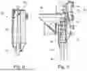
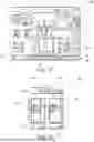
FIG. 1 shows a carrier device 10, being highly schematized, according to the invention having a device 50 for producing a material column in the ground. The carrier device 10 has a carrier vehicle 12 with a mast 20. The carrier vehicle 12 may comprise a crawler undercarriage 14, on which an upper carriage 16 can be mounted, preferably rotatably. The mast 20 can preferably be adjustably mounted on the carrier vehicle 12 by means of a linkage mechanism 18. In operation, the mast 20 can preferably be orientated essentially vertically, wherein the mast 20 can be arranged at a different angle of attack via the linkage mechanism 18 or can be arranged horizontally for transport purposes.
The mast 20 is preferably designed as a frame leader, wherein a linear guide 22 can be designed at the front of the mast 20. A mast carriage 24 can be moved along the mast 20 by means of the linear guide 22. The mast carriage 24 can be adjusted via an actuator, which may preferably comprise a linkage cable (not shown) and a cable winch.
The device 50 according to the invention for producing a material column in the ground is attached to the mast carriage 24. The device 50 has an elongated infeed pipe 52, at the upper end of which a funnel-like enlarged receiving bunker 54 is designed for receiving bulk material to form a material column in the ground. At least one material outlet opening 56 is designed at a lower end region of the infeed pipe 52, from which material outlet opening the bulk material can emerge to form a material column in the ground. Furthermore, a vibrating drive 58 is arranged in the lower region of the infeed pipe 52 above the material outlet opening 56, with which vibrating drive the infeed pipe 52, as a whole can be set into a vibrating or oscillating movement. When the vibrating drive 58 is activated, the device 50 can thus be driven vertically into the ground by its own weight and/or by an additional force being applied via the mast carriage 24.
Once a final depth has been reached, the infeed pipe 52 is retracted again, wherein bulk material, in particular gravel or sand, can be introduced into the free space formed in the ground via the material outlet opening 56 in the infeed pipe 52 to form a material column. The material flow in the infeed pipe 52 can be supported by targeted introducing of compressed air from a compressed air supply device 60. A further vibrating movement and/or a cyclical downward method (tamping) can effect to compact the material column formed in the ground, wherein the material column formed in this way can also be referred to as a vibrating tamping column.
The basic structure of a device 50 as well as the basic method for producing such a material column in the ground are known.
After the infeed pipe 52 has been driven into the ground at the latest, this pipe is filled with bulk material via the receiving bunker 54. For this purpose, a filling device 30 with a filling carriage 32 is arranged on the carrier device 10. The filling carriage 32 can preferably also be guided displaceably on the linear guide 22 on the mast 20. To raise and lower the filling carriage 32, it is connected to a hoisting cable 26, which is guided via at least one pulley 28 on a mast head 21 of the mast 20 and is connected to a cable winch 27.
To load a filling chamber 34 of the filling carriage 32, the filling carriage 32 is moved downwards along the mast 20 to a filling position on or near the ground. In this position, the filling chamber 34 can be filled with bulk material via an opening on its upper side, for example by a wheel loader. The filling carriage 32 is then moved upwards to a filling position in the region of the receiving bunker 54 by means of the cable winch 27 and the hoisting cable 26, as will be explained in more detail below.
The structure and operating mode of the filling device are described in more detail below in connection with FIGS. 2 to 4.
FIG. 2 shows the filling device 30 in a filling state. At a lower end of the filling chamber 34, which can preferably have a housing that tapers downwards like a funnel, a chute 36 is preferably extended downwards and radially outwards by means of a first adjusting cylinder 37. A closing device 40 is open, wherein a closing plate 41 is moved upwards by means of an actuator 42, which, in particular comprises a second actuating cylinder and thereby releasing a discharge opening at the lower end of the receiving chamber 34. In this state, bulk material can be discharged from the filling chamber 34 via the chute 36 into a receiving bunker (not shown here) of a device for producing a material column in the ground.
A closed state of the filling device 30 is shown in FIG. 3. In this state, the chute 36 is radially retracted again via the first adjusting cylinder 37 and moved upwards into a retracted position. The closing plate 41 is moved downwards into a closing position by means of the actuator 42, such that the filling chamber 34 is closed at the bottom. In this closed state, the filling device 30 can move along the mast and, in particular can be reloaded to receive new bulk material via the filling chamber 34 being opened at the top.
FIG. 4 shows clearly that the filling device 30 may have a filling carriage 32 with a base carriage, on which the hopper-like filling chamber 34 can be adjusted along a linear guide. This allows the filling chamber 34 to be fine-tuned to a receiving bunker without having to move the filling carriage 32 relative to a mast 20.
The filling state is described further in connection with FIG. 5. Therefor, the filling device 30 with the filled filling chamber 34 is located at a defined filling position in the region of the receiving bunker 54 on an infeed pipe 52. The representation in FIG. 5, in particular shows that a passage 55 can be open between the receiving bunker 54 and the infeed pipe 52.
The receiving bunker 54 is designed with a closed housing 66 that is substantially pressure-tight or airtight and has a closable supply opening 67. A closing device 75 with a foldable hinged opening flap 76 is designed to open and close the supply opening. The opening flap 76 can be adjusted between the opening position shown, which is swivelled inwards, and a closed position, in which the supply opening 67 is closed in a pressure-tight or airtight manner, by means of an adjustment drive 78, which can be, in particular a further adjustment cylinder.
In the opening position shown, the chute 36 of the filling device 34 can be extended and moved to or inserted into the supply opening 67, as can be clearly seen in FIG. 5. By opening the filling chamber 34, bulk material can pass from the filling chamber 34 into the receiving bunker 54 via the chute being directed diagonally downwards and thus arrive into the infeed pipe 52.
The filling device 30 is suspended from the hoisting cable 26, which is guided via at least one pulley 28 on the mast head 21 of the mast 20. In particular, a measuring device, in particular a force measuring pin, can be arranged on the axis of the pulley 28, such that the decreasing weight of the filling device 30, when the filling chamber 34 is unloaded, can be detected directly. The measuring device is connected to a control device (not shown), which can stop the filling process when a certain discharge quantity is reached. For this purpose, the closing device 40 can be actuated by the control device and the filling chamber 34 can be closed at the bottom. A certain, small quantity of bulk material can preferably be filled up directly from the filling device onto the column to be produced. The weight and quantity of the material can be detected via the measuring device, in particular the force measuring pin on the hoisting cable and added to the total column quantity in the control unit. This can improve the quality assurance.
A modified arrangement of a filling device 30 is shown schematically in FIG. 6. In particular, it is shown that the chute 36 is extended and inserted into the receiving bunker 54 for filling the receiving bunker 54. An opening flap 76 for access to the interior of the receiving bunker 54 can be pushed open and opened solely by the extending movement of the chute 36. When the chute 36 retracts, the opening flap 76 can be returned to the closed position by gravity alone and/or by spring tension.
A detailed view of a possible closing device 75 for opening and closing the supply opening 67 on the housing 66 of the receiving bunker 54 is illustrated in FIG. 7. The supply opening 67 can be closed in a pressure-tight or airtight manner by a plate-like opening flap 76. The opening flap 76 can be adjusted inwards about an upper pivot joint into an opening position by an adjustment drive 78, which can be designed as an actuating cylinder which can be pneumatically, hydraulically or electrically operated, as shown in FIG. 7. In this opening position, the chute 36 of the filling device 30 can be pushed in through the supply opening 67 on the housing 66 of the receiving bunker 54 and thus bulk material can be transferred from the filling chamber 34.
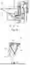
FIG. 8 shows a detailed view of a device according to the invention for producing a material column. A sensor device 70 having a first filling level sensor 71 is arranged at an upper region of a receiving bunker 54 of a device 50. The sensor device 70 is designed to detect a filling level of bulk material down to an underside of an infeed pipe (not shown here), which is arranged below the receiving bunker 54 and is connected by a passage 55. The sensor device 70 and, in particular, the first filling level sensor 71 can currently detect a filling level in the infeed pipe 52, the passage 55 and the receiving bunker 54.
Another possible design of a device 50 according to the invention is shown in FIG. 9. The sensor device 70 at the upper end of the receiving bunker 54 has two filling level sensors 71, 72. The first filling level sensor 71 can detect the filling level in the receiving bunker 54, the passage 55 and, in particular, down to a lower region of the infeed pipe 52. The first filling level sensor 71 can be, in particular, a radar sensor or a laser sensor, which generates an approximately conical detection range, which is shown schematically in FIG. 9.
It is generally clear that a detection range of the first filling level sensor 71 must be adapted to the geometric conditions of the infeed pipe, in particular its length and diameter, and must be calibrated accordingly.
In addition, in this embodiment the sensor device 70 can have a second filling level sensor 72, which is designed to detect a filling level in the receiving bunker 54. In particular, this allows a maximum filling level in the receiving bunker 54 to be reliably detected. The second filling level sensor 72 thus serves as a kind of safeguard against overfilling of the receiving bunker 54 when this bunker is filled with bulk material from a filling device 30.
FIG. 9 further illustrates a possible filling position in which the filling device 30 having the filling carriage 32 is moved directly from below to the mast carriage 24, on which the device 50 having the infeed pipe 52 is mounted.
The data recorded by the sensor device 70 and/or the measuring device, which is preferably arranged on a pulley 28 on the mast 20, can be passed to a control device for monitoring and controlling the operation of the device 50 and the method for producing a material column. The recorded data and/or control processes can be displayed and visualised by the control device to an operator of the device via a display device, in particular at least one screen. FIGS. 10 and 11 show possible types of visualisation on a screen.
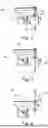
FIG. 10 shows a possible screen display 80 in which a symbolic sketch 81 of the device 50 with the infeed pipe 52 is shown in a right-hand region. A symbol 82 for the air supply indicates to the operator whether the compressed air supply device is in operation or not. A symbol 83 for the position of the opening flap indicates figuratively to the operator whether the opening flap on the receiving bunker 54 is open or closed. A current operating pressure can be specified in a field for a pressure display 84. A filling level of bulk material can be visualised to the operator both as a numerical indication and in the sketch 81 as a filling level in the infeed pipe 52. In two fields, a display 86 can be shown for a target installation quantity and for an actual installation quantity for producing the material column in the ground.
Different setting parameters can be indicated numerically in displays 87 in a left-hand region of the screen display 80. In particular, the setting parameters can indicate a hydraulic pressure, a column diameter and a bulk density of the bulk material. Preferably, the setting parameters in these fields can be entered and changed by the machine operator by using a setting function.
A display for column production 88 may be provided in a centre region of the screen display 80, which is shown in more detail below in FIG. 11.
A display for column production 88 according to FIG. 11 may comprise a target quantity display 91, in which a quantity of bulk material to be introduced is illustrated visually for each depth position, wherein a minimum introduction quantity (dotted vertical line) and a target or maximum introduction quantity (continuous vertical line) are displayed in the graphic representation. In an adjacent arranged actual quantity display 92, to the corresponding depth positions, the actual quantities of bulk material really introduced at the respective depth position can be displayed. This display is advantageous, in particular then, if the quantity of bulk material per depth position is fed in several steps, for example during insertion and during withdrawal or during repetitive tamping processes with withdrawal and reinsertion of the infeed pipe 52 into the ground. Repetitions of one or more method steps can be predefined and carried out by the control unit if, for example, the installation quantity or the hydraulic pressure at the tool tip, such as a vibrating unit tip, is not reached.
Furthermore, an actual depth with reference to the ground surface can be indicated in a display 93 and the remaining depth being remained can be indicated in a display 94 until the target depth is reached. In a further display field 95, an operating pressure can be displayed, in particular a pressure at the vibrating unit tip.
Claims
1. A device for producing a material column, in particular a vibrating tamping column, from a bulk material in the ground, having
an infeed pipe, which is designed to be driven into the ground and has at least one material outlet opening at a lower end,
a vibrating drive, which is designed to cause the infeed pipe to vibrate and is arranged, in particular, on a lower region of the infeed pipe,
a receiving bunker, which is designed to receive a quantity of bulk material and is arranged on an upper region of the infeed pipe, and
a compressed air supply device for introducing compressed air into the inside of the infeed pipe,
wherein
a sensor device is arranged, which is designed to detect a filling level of bulk material down to a lower region of the infeed pipe,
the receiving bunker is designed with a closed housing with a closable supply opening for supplying bulk material into the receiving bunker, wherein the supply opening can be closed in an airtight manner by means of a closing device, and
a passage between the receiving bunker and the infeed pipe being arranged below is open when the bulk material is introduced into the ground, wherein the filling level of bulk material in the infeed pipe can be detected by the sensor device.
2. The device according to claim 1,
wherein
the closing device has an opening flap on the receiving bunker, which can be adjusted by means of an adjustment drive between an opening position for feeding bulk material into the receiving bunker and a closing position, in which the receiving bunker is sealed in an airtight manner.
3. The device according to claim 1,
wherein
the compressed air supply device has a line arrangement having one or more supply openings which open into the receiving bunker and/or the infeed pipe.
4. The device according to claim 1,
wherein
the sensor device comprises a filling level sensor, which is designed, in particular, as a radar sensor, an ultrasound sensor and/or a laser sensor.
5. The device according to claim 4,
wherein
at least one further filling level sensor is arranged in the receiving bunker for detecting a filling level in the receiving bunker, in particular a maximum filling level in the receiving bunker.
6. The device according to claim 1,
wherein
a control unit is arranged, which is connected to the sensor device, and
the control unit is designed to control a movement of the infeed pipe and/or a discharge of bulk material into the ground via the at least one material outlet opening as a function of a filling level of the bulk material in the infeed pipe detected by the sensor device.
7. The device according to claim 6,
wherein
the control unit is designed to determine when a lower and/or upper limit filling level of bulk material in the infeed pipe has been reached and to indicate this to a machine operator and/or to initiate or terminate filling of further bulk material into the receiving bunker.
8. The device according to claim 6,
wherein
the control unit is designed to determine and, in particular, to store the current actual filling level of bulk material in the infeed pipe via a depth position of the infeed pipe in the ground.
9. A carrier device for a device for producing a material column, in particular a vibrating tamping column, in particular according to claim 1, having
a carrier vehicle,
a mast, which is arranged on the carrier vehicle and is arranged substantially vertically in operation to produce a vibrating tamping column,
a mast carriage, which is mounted, so as to be movable along the mast and on which the device for producing a vibrating tamping column is arranged, and
a filling device for filling bulk material into a receiving bunker of the device for producing a vibrating tamping column, wherein the filling device has:
a filling carriage, which can be moved along the mast,
a filling chamber formed on the filling carriage, which is designed to receive bulk material,
a closing device arranged on the filling carriage, which closes the filling chamber laterally or at the bottom, and can be adjusted between a closed movement position, in which the filling carriage can be moved along the mast, and an open discharge position, in which bulk material can be discharged from the filling chamber of the filling carriage into the receiving bunker,
wherein
a measuring device is arranged by which an actual filling quantity and/or a change in the actual filling quantity of bulk material in the filling chamber can be detected,
an actuator is arranged on the closing device, with which actuator the closing device can be opened and closed in a defined manner, and
a control unit is arranged, which is connected to the measuring device and the actuator and is designed for the controlled supply of a specific quantity of bulk material from the filling chamber of the filling device into the receiving bunker of the device for producing a vibrating tamping column.
10. The carrier device according to claim 9,
wherein
a defined filling quantity can be preset by the control unit, which quantity of bulk material is to be discharged by the filling device to the receiving bunker, and
the control unit opens the closing device and closes it again depending on a change in the actual filling quantity of bulk material in the filling chamber detected by the measuring device when the defined filling quantity of bulk material has been discharged.
11. The carrier device according to claim 9,
wherein
the measuring device is designed to detect a weight force of the filling device.
12. The carrier device according to claim 9,
wherein
the filling carriage is guided along a linear guide of the mast and can be moved on the mast by means of a hoisting cable.
13. The carrier device according to claim 12,
wherein
the hoisting cable is guided on the mast via a pulley on which the measuring device is arranged, which detects a weight force as a measure of the actual filling quantity.
14. A method for producing a vibrating tamping column from a bulk material in the ground, in particular having a device according to claim 1, having
an infeed pipe, which is designed to be driven into the ground and has at least one material outlet opening at a lower end, and
a receiving bunker, which is arranged on an upper region of the infeed pipe,
wherein
the infeed pipe is driven into the ground,
the receiving bunker is used to fill the infeed pipe with a quantity of bulk material, and
the bulk material is discharged into the ground via the at least one material outlet opening on the infeed pipe, wherein the infeed pipe is vibrated by means of a vibrating drive and compressed air is introduced into the inside of the infeed pipe by means of a compressed air supply device to support the material flow in the infeed pipe,
wherein
a sensor device is arranged in the region of the receiving bunker, with which sensor device a filling level of bulk material can be detected down to a lower region of the infeed pipe,
the receiving bunker is designed with a closed housing with a closable supply opening for supplying bulk material into the receiving bunker, wherein when compressed air is introduced by means of the compressed air supply device, the supply opening is closed in an airtight manner by means of an opening flap, and,
when the bulk material is introduced into the ground, the filling level of bulk material in the infeed pipe is detected by the sensor device, wherein a passage between the receiving bunker and the infeed pipe being arranged below, is open when the bulk material is introduced into the ground.
15. A method for filling a device for producing a material column, in particular a vibrating tamping column, in particular according to claim 1, by means of a carrier device, wherein the carrier device comprises:
a carrier vehicle,
a mast, which is arranged on the carrier vehicle and is arranged substantially vertically in operation to produce a vibrating tamping column,
a mast carriage, which is mounted, so as to be movable along the mast and on which the device for producing a vibrating tamping column is arranged, and
a filling device for filling bulk material into a receiving bunker of the device for producing a vibrating tamping column, wherein
a filling carriage of the filling device is moved along the mast,
a filling chamber formed on the filling carriage receives bulk material,
a closing device arranged on the filling carriage, which closes the filling chamber laterally or at the bottom, is adjusted between a closed movement position, in which the filling carriage can be moved along the mast, and an open discharge position, in which bulk material is discharged from the filling chamber of the filling carriage into the receiving bunker,
wherein
an actual filling quantity and/or a change in the actual filling quantity of bulk material in the filling chamber is detected by means of a measuring device,
the closing device is opened and closed in a defined manner by a control unit by means of an actuator, and
a control unit is connected to the measuring device and the actuator and controls a supply of a specific quantity of bulk material from the filling chamber of the filling device into the receiving bunker of the device for producing a vibrating tamping column.
Images & Drawings included:


Sources:
- United States Patent and Trademark Office - verify current appl. status at the USPTO↗
Similar patent applications:
Recent applications in this class:
- » 20250257540 2025-08-14
SIDE GRIP VIBRATORY PILE DRIVER - » 20250250760 2025-08-07
VARIABLE MOMENT VIBRATORY SYSTEMS AND METHODS - » 20250019920 2025-01-16
VIBRATION DEVICE AND METHOD FOR INSERTING INTO THE GROUND OR REMOVING FROM THE GROUND A FOUNDATION ELEMENT WITH ELECTRIC MOTOR - » 20250012031 2025-01-09
VIBRATION DEVICE WITH BASE FRAME AND METHOD FOR INSERTING INTO THE GROUND OR REMOVING FROM THE GROUND A FOUNDATION ELEMENT BY PROVIDING SAID VIBRATION DEVICE - » 20240229401 2024-07-11
CLAMPING SYTEMS, METHODS, AND APPARATUS FOR DRIVING CAISSONS INTO THE EARTH - » 20240011235 2024-01-11
Pile driving apparatus - » 20230392338 2023-12-07
Pile Driving Apparatus And Construction Machine - » 20230002996 2023-01-05
Electrically-driven vibratory hammer - » 20220349145 2022-11-03
Vibro-hammer having side grip - » 20220290396 2022-09-15
SHAKER FOR GENTLE DRIVING OF PILES
Recent applications for this Assignee:
- » 20250250758 2025-08-07
METHOD AND DEVICE FOR PRODUCING A FOUNDATION ELEMENT IN THE GROUND FROM A SOIL MORTAR - » 20250179758 2025-06-05
TRENCH CUTTER AND METHOD FOR MAKING A CUT TRENCH IN THE GROUND - » 20250137225 2025-05-01
GRAB DEVICE AND METHOD FOR OPERATING A GRAB DEVICE - » 20250067018 2025-02-27
CIVIL ENGINEERING DEVICE AND METHOD FOR OPERATING A CIVIL ENGINEERING DEVICE - » 20250043636 2025-02-06
DRILLING TOOL AND METHOD FOR PRODUCING A BORE IN THE GROUND - » 20240360726 2024-10-31
DRILLING TOOL AND METHOD FOR PRODUCING A BORE IN THE GROUND - » 20240337088 2024-10-10
GRAB DEVICE AND METHOD FOR OPERATING A GRAB DEVICE - » 20240240427 2024-07-18
DIAPHRAGM WALL CUTTER AND METHOD FOR CUTTING A CUTTING TRENCH IN THE GROUND - » 20240229404 2024-07-11
MEASURING ARRANGEMENT AND REMOVAL DEVICE WITH A MEASURING ARRANGEMENT - » 20240209726 2024-06-27
Soil working device and method for creating a substantially vertical hole in the ground