EROSION CONTROL STRUCTURE
US20250257543A1
2025-08-14
19/051,608
2025-02-12
Smart Summary: An erosion control structure is designed to protect slopes from erosion. It consists of blocks that are tied together to form a closed or partially closed loop. These blocks are placed at the bottom of a slope, known as the toe, where erosion is most likely to occur. The structure helps hold the soil in place and prevents it from washing away. Overall, it provides a simple and effective way to maintain the stability of sloped areas. 🚀 TL;DR
Abstract:
A system including a closed loop or partially closed loop structure, including tied blocks, positioned at or adjacent to a toe of a slope.
Inventors:
- Matthew James Motz 4 🇺🇸 Cincinnati, OH, United States
- Sean Robert Stallo 3 🇺🇸 Cincinnati, OH, United States
- Judd Clayton Cashatt 1 🇺🇸 Austin, TX, United States
Applicant:
Interested in similar patents?
Get notified when new applications in this technology area are published.
Classification:
E02D17/202 » CPC main
Excavations; Bordering of excavations; Making embankments; Securing of slopes or inclines with flexible securing means
E02B3/123 » CPC further
Engineering works in connection with control or use of streams, rivers, coasts, or other marine sites ; Sealings or joints for engineering works in general; Structures or apparatus for, or methods of, protecting banks, coasts, or harbours; Revetment of banks, dams, watercourses, or the like, e.g. the sea-floor; Flexible prefabricated covering elements, e.g. mats, strips mainly consisting of stone, concrete or similar stony material
E02D17/20 IPC
Excavations; Bordering of excavations; Making embankments Securing of slopes or inclines
E02B3/12 IPC
Engineering works in connection with control or use of streams, rivers, coasts, or other marine sites ; Sealings or joints for engineering works in general; Structures or apparatus for, or methods of, protecting banks, coasts, or harbours Revetment of banks, dams, watercourses, or the like, e.g. the sea-floor
Description
This application claims priority to U.S. Provisional Application Ser. No. 63/552,335 filed on Feb. 12, 2024 and entitled Erosion Control Structure, the entire contents of which are hereby incorporated by reference.
The present disclosure is directed to an erosion control structure, and more particularly, to an erosion control structure that can include tied blocks.
BACKGROUND
Erosion control structures are typically used to limit the bulk movement and/or entrainment of dirt and/or soil. Such erosion control structures are often desired to be located on inclined surfaces or substrates. In particular, such erosion control structures may often be located at the bottom of the inclined surface or substrate, adjacent to a shoreline or sharp drop-off, where the erosion control structure can serve as a lip or anchor. In these cases the erosion control structure can enable a build up of soil and vegetation above and behind the erosion control structure.
Erosion of shorelines and the like present numerous challenges including erosion and downstream pollution of waterways, safety concerns for human and animal entrance and egress, undesirable aesthetics, and increased maintenance costs. Typically, the bank adjacent to a lake, pond, stream, river or other waterway is unstable at the interface of the bank and the water level, commonly known as the toe of the slope. In particular in some cases the toe of a slope may collapse due to oversaturation with water, and/or may erode due to water or wave action.
Existing erosion control structures that are positioned on inclines and/or at shorelines can be difficult and expensive to manufacture and deploy, and/or may not be sufficiently effective to retain soil to provide the desired build up above/behind the erosion control structure. Other existing erosion control structures that are used on flat surfaces can have similar challenges.
SUMMARY
In one embodiment the present disclosure is directed to an erosion control structure that can be located on an incline and/or at a shoreline, and that can operate as a lip or anchor to provide a build up of soil and vegetation behind the erosion control structure. In other embodiments the erosion control structure can be used on flat surfaces. The erosion control structure is relatively quick and easy to assemble, and can provide a strong and long-lasting anchor/support that is relatively inexpensive to procure and install. More particularly, in one embodiment the invention is directed to a system including a closed loop or partially closed loop structure, including tied blocks, positioned at or adjacent to a toe of a slope.
BRIEF DESCRIPTION OF DRAWINGS
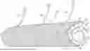
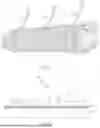
FIG. 1 is a perspective view of one embodiment of an erosion control structure;
FIG. 2 is a side view of a portion of the erosion control structure of FIG. 1, in a flat/unrolled state, and positioned on a ground surface;
FIG. 3 is a top view of a tied block mat which can be used to make part of the erosion control structure of FIG. 1;
FIG. 4 is a perspective view of a portion of the tied block mat of FIG. 3;
FIG. 5 is a side view of another erosion control structure, shown positioned at a toe of a slope;
FIG. 5A shows the erosion control structure of FIG. 5, with soil infill located therein;
FIG. 6 is a side view of another embodiment of the erosion control structure, shown positioned at a toe of a slope, with soil built up above/behind the erosion control structure;
FIG. 7 is a side view of another embodiment of the erosion control structure;
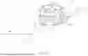
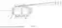
FIG. 8 is a perspective view of another embodiment of the erosion control structure, shown positioned at the toe of a slope;
FIG. 9 is a side view of another embodiment of the erosion control structure;
FIG. 10 is a perspective view of the erosion control structure of FIG. 10, shown positioned at the toe of a slope and at/adjacent to a body of water;
FIG. 11 is a side view of another embodiment of the erosion control structure;
FIG. 12 is a side view of another embodiment of the erosion control structure;
FIG. 13 is a side view of another embodiment of the erosion control structure;
FIG. 14 is series of perspective views showing one method for forming an erosion control structure;
FIG. 15 is a side view of another embodiment of the erosion control structure;
FIG. 16 is a perspective view of an erosion control structure, positioned in a channel/ditch; and
FIG. 17 is a side cross section taken along line 17-17 of FIG. 16.
DETAILED DESCRIPTION
One embodiment of an erosion control structure, generally designated 10 shown in FIG. 1, can in one case be made of or include a closed loop structure (or substantially or partially closed loop structure) of tied block 12, that is (in one case) wrapped about/positioned about a core or core material 14. The structure 10 can in one case be termed a concrete block erosion roll (“CBER”). As shown in FIGS. 2-4, in one embodiment the closed loop structure 12/tied block structure 12, when laid flat, includes or takes the form of an array of blocks 16 that are coupled to an adjacent, flexible grid/mesh material 18. In the illustrated embodiment each block 16 has a truncated pyramid shape, having a base 20 on its underside, the base 20 having a bottom surface 21 and, in one case, four rectangular surfaces 23 extending about a perimeter of the base 20 (see FIG. 4). Each block 16 can have with four angled sides 22 extending away from the base 20 (upwardly from the base 20, when laid flat in the configuration of FIGS. 2-4). Each side 22 is inclined inwardly (moving in a bottom-to-top direction) relative to the associated block 16. Each block 16 can have a flat, square top surface 24 positioned at a top of each side 22, oriented parallel to the base 20/bottom surface 21.
In one embodiment each block 16 can have a size of between about two inches and about eighteen inches square at the base 20, have a height of between about one inch and about ten inches, and have a spacing therebetween of between about one inch and about three inches. Each block 16 can be made of cast concrete, but if desired can be made of other materials included but not limited to clay, plastics, polymers, fiberglass, composite materials, rubber, synthetic rubber, cement (including hydraulic cement), cement mixed with gravel, sand and/or other aggregates, combinations of these materials and the like. In addition, it should be understood that each block 16 can have various other shapes besides the truncated pyramid shape shown in the figures, including for example in one case a generally rectangular prism shape (including cubes or cuboids), pyramids, or the like.
The grid/mesh material 18 can take any of a wide variety of shapes and forms, and in one case is a geogrid, such as a geosynthetic material used to reinforce soils and ground surfaces, and which can resist tensile forces. The grid/mesh material 18 can be made of or include plastic and/or polymer material, such as polypropylene, and more particularly biaxial polypropylene yarn, which may in one case be coated with a polymer to provide resistance to degradation due to exposure to ultra-violet radiation and weathering. In one case a suitable grid/mesh material 18 is FORNIT® 30/30 biaxial geogrid, manufactured by HUESKER Synthetic GmbH of Gescher, Germany. The grid/mesh material 18 can also or instead take the form of other tensile elements such as rope, wire, cable, or string made of polymers, plastic, metal, cotton, or other materials.
While each block 16 can be relatively rigid, the grid/mesh material 18 may have sufficient flexibility to enable the mesh material 18 to be folded about itself, and to enable the tied block structure 12 to be rolled into, and assume, the rolled/generally tubular or cylindrical shape shown in FIG. 1. The grid/mesh material 18 can have or define a grid of strands 25 that are arranged perpendicular to each other, or are arranged at other angles, to define gaps 26 therebetween (see FIGS. 3 and 4). In one case the gaps 26 are at least about ¼″ square (or have an average surface area of at least about 0.0625 square inches) about so that liquids and small particulates can pass therethrough, and in one case the gaps 26 are about 1.35″ square.
The grid/mesh material 18 can be coupled to the blocks 16 to form the tied block structure 12. In one embodiment, the grid/mesh 18 is embedded in a lower portion of each block 16, adjacent to and parallel to the base 20/bottom surface 21 of each block 16. In particular, in one case, when the blocks 16 are made of concrete and/or a hardenable paste, the grid/mesh 18 can be embedded in each block 16 during the formation of the blocks 16, for example when each block 16 is made of liquid/slurry concrete. The concrete blocks 16 can then be allowed to cure and harden, anchoring each block 16 to the grid/mesh 18.
In another embodiment, the grid/mesh 18 includes or takes the form of a three-dimensional mat of interconnected fibers, where the “three-dimensional” mat can have an open weave or mesh component having a loft or thickness that is at least about 5 mm in one case and/or less than about 25 mm. In this case the grid/mesh 18 can be a geotextile and/or loop matting that has outwardly protruding filaments that can project into the base 20 of each block 16 when the block 16 is curing, to thereby bond the grid/mesh 18 and the blocks 16. In this case the grid/mesh 18 can be placed against the blocks 16 when the blocks 16 are curing, rather than being deeply embedded in to the blocks 16, details of which can be found in U.S. Pat. No. 11,198,231, the entire contents of which are incorporated by reference herein. However if desired the blocks 16 can be coupled to the grid/mesh 18 by various other means and mechanisms, including adhesives, via the use of mechanical fasteners, and the like.
The core 14, if utilized, can define, be located at and/or overlap with a geometric center of the erosion control structure 10, and can take a variety of forms and be made from various materials. In one embodiment the core 14 is made of or includes structural core material 13 such as excelsior (e.g. wood shavings) and/or wood wool, such as Curlex CL Blankets by American Excelsior Co. of Rice Lake, Wisconsin. However it should be understood that the core material 13 can be made of any of a wide variety of materials, including natural/organic materials such as straw, wood fibers, hay, mulch, compost, and/or synthetic materials such as lightweight synthetic fibers, fiberglass, shredded or small pieces of rubber, polymers, styrofoam, or the like. The core 14 can in one case include a netting or mesh material 15 (see FIGS. 1 and 5) that retains the core material 13 in the desired shape, or alternatively the core 14 can include the core material 13 that is dimensionally stable and thus does not need any netting or mesh material 15. Further alternatively, the core material 13 can simply be located/retained loose inside/at a center of the tied block structure 12, without using the netting or mesh material 15 (see FIG. 7). The core 14/core material 13 can be made of a material that is sufficiently strong to support the tied block structure 12 in a closed loop shape or substantially/partially closed loop shape, and resist degradation when exposed to external environmental conditions, for at least about twelve months in one case.
Regardless of the material chosen, the core 14 (i.e. including the core material 13 and/or outer netting 15) in one embodiment is made of water and/or soil permeable material, and/or the core 14 may as a whole be water and/or soil permeable. In addition, the core 14 can be made of material having, and/or as a whole have, a relatively small density and/or weight. In particular, the core 14 can in some cases merely operate as a structural placeholder to retain the tied block structure 12 in the closed (or substantially/partially closed) loop shape. In that case it can be desired to reduce the weight/density of the core 14 to reduce the weight/density of the erosion control structure 10, which provides ease of transportation, handling and placement.
Accordingly in one case the core 14 is made of a material different from the tied block structure 12 and/or the blocks 16, and has a density at least 50% less than a density of the material of the blocks 16, and at least about 75% less in another case. However, if desired the core 14 can also have a density equal to or greater than the density of the blocks 16, for example where it is desired for a relatively dense core 14 to add additional weight and stability to the structure 10.
In order to provide sufficient weight reduction and/or cost savings, in some case the core 14 may be relatively large. In particular, the core 14 can in one case have a volume that is or constitutes at least about 10% of a volume of the erosion control structure 10/closed loop structure 12, or have a volume that is at least about 20% of a volume of the erosion control structure 10/closed loop structure 12 in another case, or at least about 30% in yet another case. However, in other cases the core 14 can provide a smaller volume, and indeed in alternate embodiments described in greater detail below the erosion control structure 10 may not include a core 14 at all.
FIG. 1 shows the core 14 in the form of a single, generally tubular or cylindrical component. However the core 14 can have any of a wide variety of shapes and structures. For example, in the embodiment of FIG. 6, the core 14 includes two core portions 14a, 14b, each taking the form of a tube or cylinder positioned side-by-side, and located inside the closed loop structure 12. Thus core 14 can thus include and/or be made of one, two, three or more core portions, and have any of a wide variety of shapes.
The erosion control structure 10 can include an outer liner 28 extending at least partially about an outer surface of the tied block structure 12. In particular as shown in FIG. 1 the liner 28 extends about, and covers, of an outer surface area of the tied block structure 12, extending from a bottom center (6 o'clock) position of the tied block structure 12, to a top center (12 o'clock) position of the tied block structure 12, and thus extends about 180 degrees about the tied block structure 12 in the illustrated embodiment. Thus the liner 28 may not extend about an entirety of the closed loop structure 12 (e.g. extends less than 360 degrees), for reasons which will be described in greater detail below.
In the embodiment of FIG. 5, the liner 28 extends about, and covers, of an outer surface area of the tied block structure 12, extending from a position slightly offset from, in the downstream direction) bottom center (about a 7 o'clock position) of the tied block structure 12, but in contact with the substrate 34, to a midheight position (3 o'clock) position, and thus extends about 270 degrees about the tied block structure 12. The liner 28 can extend about/cover at least 30% of an outer surface area of the tied block loop structure 12 in one case (e.g. extending about 120 degrees in end view), leaving up to 70% of the outer surface area (e.g. about 60 degrees) uncovered. Conversely, in another case the liner 28 does not extend about/cover at least about 30% (e.g. about 120 degrees) of the outer surface area of the tied block loop structure 12. In another case the liner 28 can extend about/cover at least 50% of an outer surface area of the tied block loop structure 12 (e.g. extending about 180 degrees in end view), leaving up to 50% of the outer surface area (e.g. about 60 degrees) uncovered.
The liner 28 can be water permeable in one case (e.g. have openings or pores 3A or
greater in average diameter (or average effective diameter, where an effective diameter can be used for non-circular openings, where the effective diameter of a non-circular opening is a diameter that provides the same surface area as the surface area of the non-circular opening) in one case) and soil impermeable in one case (e.g. the liner can have openings or pores 0.002 mm or less in average diameter (or average effective diameter) in one case, or 0.020 mm or less in average diameter (or average effective diameter) in another case, or 0.050 mm in average diameter (or average effective diameter) in yet another case). Alternatively the liner 28 can be both water impermeable and soil impermeable, or even water permeable and soil permeable if desired.
The liner 28 can be loosely held in place against the tied blocks 12, or can be glued, affixed or cast into the tied block structure 12. In another case the liner 28 is integrally coupled and/or formed with the tied block structure 12. The liner 28 can include or take the form of a geotextile, textile, a film or matting including polymers/plastics, jute, hemp, straw, PVA, cotton, ferrous or non-ferrous material.
With reference to FIGS. 1 and 6 for example, the erosion control structure 10 can include an plurality of elongated support members 30 coupled to the tied block/closed loop structure 12, and extending away therefrom. In one case the elongated support members 30 are coupled to or terminate adjacent to a radially outer surface of the tied block structure 12 and/or the mesh material 18 and/or the liner 28. The support members 30 can take the form of straps, ropes, chains, cables or the like that can transmit tension forces. Each support member 30 can have a length of at least about three feet in one case, and at least about six feet in another case. Various support members 30 can be spaced along the axial length of the structure 10, such as at a spacing between one foot and ten feet along the length of the structure 10 in one embodiment.
In order to form the erosion control structure 10, a flat of tied block mat 12, such as shown in FIGS. 2 and 3, can be provided, and as also shown in FIG. 14A. A core 14 (if desired) can then be placed on the tied block mat 12 as shown in FIG. 14B. The mat 12 can then rolled about the core 14, and about axis 31 (FIGS. 2, 3 and 14B) such that the flat layer of tied block 12 is rolled or coiled about the core 14 in a generally circular or generally spiral/helical shape, as shown in FIG. 14C. It is noted that the mat 12 can be rolled about axis 31 (extending parallel to the greatest length of the mat 12), which can be perpendicular to the axis 33 (extending perpendicular to the greatest length of the mat 12 in one case) (FIG. 3) about which the tied block mat 12 can be rolled during storage/shipping. Rolling up the mat 12 about the lengthwise axis 31 can enable the structure 10 to have a relatively long length, such as at least about ten feet long in one case, or at least about twenty feet long in another case. However, if desired, the mat 12 can be rolled about axis 33, or other axes to create the structure 10. It is also noted that although the figures show the mat 12 rolled such that the top surfaces 24 of the blocks 16 are positioned radially inwardly, the mat 12 can be rolled in the opposite direction such that the “top” surfaces 24 of the blocks 16 are positioned/face radially outwardly. Once formed the structure 10 can, in one case, have a height between twenty inches and sixty inches, a width between twenty inches and sixty inches, and a length between three feet and fifty feet.
The tied block mat 12 can have the liner 28 coupled thereto (positioned thereunder, as shown in FIG. 2) and underlying at least an entire surface area of the tied block mat 12, prior to rolling up the mat 12, which can result in the structure shown in FIGS. 7-11 after the tied block mat 12 rolled. In an alternative embodiment, the liner 28 may not be coupled to the mat 12 prior to rolling, and instead the liner 28 can be placed on the mat 12 after rolling (or the liner 28 may underline only a portion of the tied block mat 12 prior to rolling), which can result in the structure shown in FIGS. 1, 5, 5A and 6. In yet another embodiment, as shown in FIG. 12, the structure 10 can be entirely encased within a (tubular) sleeve of liner material 28, such that the liner 28 encapsulates the structure 10 therein.
When a core 14 is utilized, in some cases it may be desired to limit the number of layers of the tied block mat 12 that is rolled about the core 14. In particular, in the embodiment shown in FIG. 1 the tied block mat 12 is rolled about itself generally only once, with a limited overlap (between about 15 degrees and about 90 degrees in one case) to ensure the tied block mat 12 forms a closed loop, and remains in the closed loop. Thus in the illustrated embodiment at least about 50% of the structure 10 (measured in the circumferential direction) has only a single layer (in the radial direction) of tied block mat 12, and the tied block mat 12 does not form more than two layers in radial direction at any location. However in other cases the structure 10 can have multiple layers of tied block mat 12, overlapping in the radial direction as will be described in greater detail below.
Once the structure 10 is formed, it can be lifted and moved to the desired location, such as at the toe 32 of a slope/substrate 34 (which can be soil, or local grade) as shown in FIGS. 5, 5A and 6. The toe 32 of the slope 34 can be a bottom edge of the slope 34, and can in some cases be positioned at or adjacent to a body of water 36. In one case, the structure 10 can be positioned adjacent to the toe 32 of the slope such that the structure 10 is entirely positioned on the slope/substrate 34, and the leading/downstream edge of the of the structure 10 is spaced away from the toe 32 by not more than an effective diameter of the structure 10, or in another case is spaced from the toe 32 by no more than 2× the effective diameter, or in another case no more than 5× the effective diameter.
When positioned adjacent to a body of water 36, in one case a lower-most portion, upper-most portion, or center of each structure 10 is located no more than about three inches above the body of water 36, or alternatively and the leading/downstream edge 43 of the structure 10 in contact with the substrate 34 is spaced away from the body of water 36 by not more than an effective diameter of the structure 10, or in another case is spaced from the body of water 36 no more than 2× the effective diameter, or in another case no more than 5×, or in another case no more than 10x, the effective diameter. In some cases the water 36 can at least temporarily reach to the center, or higher, of the structure 10, as shown in FIG. 6, although the level of the water 36 can rise and fall due to irrigation, precipitation or evaporation, and in addition the level of water 36 can be adjusted by temporarily draining water during the installation process.
The structure 10 can be lifted and moved into position onto the substrate 34 via the support members 30 in one case, and carried out using mechanical equipment such as fork lifts, excavators, or the like. The structure 10 can have some flexibility along its longitudinal direction, and thus can be positioned as desired to conform to the curvature of a given toe 32 desired. Once the structure 10 is roughly positioned at the toe 32 the support members 30 can be pulled to position the structure 10 in the desired location and/or height and at the desired curvature. In addition, multiple structures 10 can be positioned longitudinally end-to-end along the toe 32 and provide continuous erosion control along the toe 32.
Once the structure 10 is positioned at the desired location to, each support member 30 can be pulled taut in the uphill direction, and then anchored in place in the underlying (soil) substrate 34. For example, as shown in FIGS. 6, 8 and 10, an anchor 40 (such as a steel t-post, a plastic or wood stake, percussion or screw earth anchor, or other types of soil anchor) can be passed through each support member 30 and into the substrate 34 to anchor the structure 10 in place. Thus each support member 30 can be coupled to the closed loop structure 12 at a lower end of the support member 30, and be coupled to the substrate 34 at an upper end thereof. Instead of being coupled to the substrate 34, each support member 30 and/or anchor 40 can also or instead be coupled to a hardened material/substrate, such as a concrete wall or a wooden bulkhead. In addition, if desired percussion driven earth anchors (not shown) can be driven through the structure 10 in and into the substrate 34 to further anchor the structure(s) 10 in place.
As noted above, the liner 28 can in some cases be positioned to not cover at least part of the upper or upstream portion of the structure 10 (e.g. “upper” or “upstream” with regard to the slope of the substrate 34 and/or the flow of water from precipitation flowing down the substrate 34), and to cover at least part of the lower or downstream portion of the structure 10, and in one case covers the downstream-most portion of the structure 10 that is in contact with the substrate 34. In one case the liner 28 does not cover the upstream-most portion 45 of the structure that is in contact with the substrate 34 (e.g. the approximately 5 o'clock location of the structure of FIG. 5). Once the structure 10 is positioned and anchored in place, in one case soil and/or water, such as wet soil and/or spoil dredged from the floor of bed or an adjacent body of water 36, can be scooped, pumped, or otherwise placed immediately uphill of the structure 10. Alternatively water and/or soil can be transported to the site of the structure 10 from a different location. In either case the water and/or soil can then enter the structure 10 from the uphill side, and fill/permeate the core 14, or other volume inside the structure 10/closed loop structure 12, shown as soil infill 37 in FIG. 5A. In particular, soil can become embedded in the core 14 and/or portions of the tied block 12, trapped by the fibers or other materials of the core 14. When the liner 28 is water permeable and soil impermeable, introduced water can freely flow out of the core 14/structure 10 and through the liner 28, leaving the trapped soil 37 behind. In one case, the soil 37 located in the structure 10 fills at least about 10% of an inner volume of the structure 10, or at least about 20% in another case, to ensure sufficient weight inside the structure 10.
Water/soil can be continued to be added to the upstream of the structure 10 as desired until the structure 10 is saturated with soil in the desired amount. In the embodiment of FIG. 6, the structure 10 has been essentially immersed in soil to create the backfilled area 39. In an alternative embodiment, water and/or soil are not mechanically added during the placement/assembly process, and instead the structure 10 can (if desired) rely upon the natural migration of water/soil over time to introduce soil into the core 14/structure 10. The trapped soil 37 adds weight the structure 10, helping to anchor and stabilize the structure 10. In this manner, additional anchoring weight and volume of the structure 10 is provided on-site by existing, available materials (namely, soil), and the structure 10 does not need to be pre-loaded with anchoring weight and volume. Thus the ability to providing anchoring mass and weight on-site enables a reduction in transportation and manufacturing costs.
As noted above, the liner 28 can be located on the lower or downstream side of the structure 10, covering the associated outer surface, and not located on the upper or upstream side of the structure 10, not covering the associated outer surface. By not positioning the liner 28 on the upstream side of the structure 10, soil is free to enter and infiltrate the core 14 and other portions of the structure 10. Conversely, by positioning the liner 28 on the lower side of the structure 10, when the liner 28 is soil impermeable, soil is trapped in the core 14 and other inner portions of the structure 10. When the liner 28 is water permeable, water can flow through the core 14, leaving the soil behind.
Once the structure 10 is located and sufficiently anchored in place, if desired the volume above and upstream of the structure 10 can be backfilled with soil or other backfill material, in one case adding backfill 39 up to the top of the structure 10, as shown in FIG. 6. The backfilled area 39 and/or the upper surface of the structure 10 can then be seeded with vegetation (such as grasses) to provide further stability, if desired.
In an alternative embodiment, as shown in FIGS. 7 and 8, the structure 10 can have a generally flat and planar, or sheet-like, extension portion 42 or extension portions 42, 44, that are positioned on the substrate 34, and extend above and/or below the structure 10. In the embodiment of FIGS. 7 and 8 the structure 10 includes an upper extension portion 42. Thus when the structure 10 is used adjacent to a toe slope 32, the upper extension portion 42 can extend in the upper or upstream direction, on adjacent dry land, and conform to the underlying substrate. In the embodiment of FIG. 8 the structure 10 includes both an upper extension portion 42 and a lower extension 44 portion that extends below/downstream of the structure, on and conforming to the bed/floor of the adjacent body of water 36 in one case.
The extension portions 42, 44 can each be generally flat, planar, flexible mats that conform to the underlying substrate 34 and act as scour aprons, reducing erosion by reducing scouring action at those locations covered by the extension portions 42, 44. The extension portions 42, 44 can also help to secure the structure 10 in place due to friction, and/or soil that is positioned on and/or above the extension portions 42, 44 and/or by placing anchors through the extension portions 42, 44. In the illustrated embodiment, each extension portion 42, 44 is not shown as including any blocks 16 thereon. However it should be understood that blocks 16 can be positioned on one or both of the extensions portions 42, 44, on all or part thereof, and coupled to the underlying flexible mat portion. The use of such blocks 16 can provide erosion control and/or provide a habitat that encourages growth of marine plants and animals.
Each extension portion 42, 44 can extend away from the tied block structure 12 in the upper/lower direction at least about two feet in one case, or at least about six feet in another case, and less than about thirty feet in one case. In the illustrated embodiment each extension portion 42, 44 has the same length, along the central axis of the structure 10, as the tied block mat 12, but the extension portions 42, 44 can have a greater or lesser length as desired.
Each extension portion 42, 44 can be made of a variety of materials. In one case as shown in FIG. 7 one or each extension portion 42, 44 is made of the same material as the liner 28, and can be integrally/seamless formed with or coupled to the liner 28 extending around the tied block mat 12. In another embodiment one or each extension portion 42, 44 is made of the same material as the grid/mesh 18, and can be integrally/seamless formed with or coupled to the grid/mesh 18 forming part of the tied block mat 12. However the extension portions 42, 44 can be made of any of a wide range of materials, and can be coupled to the tied block mat 12 and/or liner 28 as desired.
In order to form the structure 10 with the extension portion 42 and/or 44, the process can begin with a generally flat layer of tied block mat 12 shown in FIG. 14A, which includes the liner 28 having a portion positioned below part of the tied block mat 12, and a portion 42 extending beyond the tied block mat 12. The core 14, if utilized, can then be positioned on the tied block mat 12 as shown in FIG. 14B. Next the tied block mat 12 can be rolled about the core 14, as shown in FIG. 14C into a generally circular or spiral shape. The portion 42 of the liner 28 extending beyond the tied block mat 12 can then be used as an extension portion 42, as shown for example in FIGS. 7 and 8.
In addition, in another embodiment, the structure 10 can include extension portions (not shown) that extend in the longitudinal direction parallel to the central axis, rather than radially (uphill and/or downhill). The longitudinally extending extension portion can be positioned below longitudinally-adjacent structures 10 to help to provide continuous erosion control and prevent soil loss between adjacent structures 10.
In another alternate embodiment shown in FIGS. 9 and 10, the liner 28 extends about the structure 10/tied block mat 12 at least 360 degrees, in a helical configuration in end view to form a closed loop or a tubular structure. In this embodiment the liner 28, when the liner 28 is soil impermeable, may somewhat block the entrance of soil into the core 14 (if utilized) compared to the embodiment of, for example, FIGS. 5 and 5A. However in the embodiments of FIGS. 9 and 10 soil may still find its way into the core 14/center of the structure 10 and be retained therein. In other cases however the structure 10 may be sufficiently weighty and the structure 10 may not necessarily need the core 14 to become saturated with soil.
In yet another alternate embodiment, as shown in FIG. 11, the structure 10 does not include the core 14. In this case the structure 10 can still act as an erosion control structure, can be still be filled up with soil at the time of installation, or over time if desired, to remain anchored in place. Alternatively the structure 10 may not necessarily need to be filed with soil. In yet another embodiment, as shown in FIG. 13, the structure 10 can form closed loop structure, but the closed loop may not be entirely formed by the tied block mat 12. For example, in this case the tied block mat 12 may extend only about 180 degrees (or at least about 180 degrees in one case) (e.g. from about the 6 o'clock position to about the 12 o'clock position, or on the downstream side of the substrate 34/toe 32), and straps or other tensile elements 46 can extend the remaining amount (180 degrees in this case) and are coupled to the tied block mat 12/liner 28 at both ends thereof. In addition, in one case the structure 10 may not form an entirely closed loop (e.g. can extend less than 360 degrees), but can instead form a partially and/or substantially closed loop, extending at least about 180 degrees in one case, or at least about 220 degrees in one case, or at least about 270 degrees in another case, or at least about 300 degrees in yet another case, and the structure 10 may be able to retain its substantially closed loop shape due to the weight of the tied block mat 12 and/or anchoring components.
In another embodiment shown in FIG. 15, the structure 10 is positioned on a flat or generally flat substrate or ground surface 34. An anchoring structure 48, such as rebar, can be passed entirely through the structure 10 and embedded in the ground surface 34 to help retain the structure 10 in place. In addition, the liner 28 (either with or without blocks 12 thereon) can extend upstream (relative to the direction of expected water flow) as an extension portion 42, and an upstream location of the extension portion 42/liner 28 can be held in place via an anchor 40. In this configuration the structure 10 can operate as a rock dam, located at the toe of a slope and/or at a generally flat location to retain soil and/or prevent erosion.
In some of the embodiments described and shown above, the structure 10 is oriented such that its central axis 31 is parallel (or generally parallel, accounting for natural variances in the slope 34 and the flexible shape/positioning of the structure 10) to a length of the toe 32 of the slope 34. In the embodiment of FIGS. 16 and 17, the structure 10 is oriented such that its central axis 31 is oriented perpendicular (or generally perpendicular, accounting for natural variances in the slope 34 and the flexible shape/positioning of the structure 10) to the toe 32 of the slope 34 (or, more specifically, perpendicular to two opposed slopes 34 (including a second or “supplemental” slope 34 as shown). In particular in this embodiment the structure 10 is located in, and spans the length of, channel/ditch 50 (collectively termed a “channel” herein). The structure 10 of this embodiment can include a downstream extension portion 42, which can be made of the grid/mesh material 18. In one case the structure 10 includes a plurality of support members 30 spaced along its length, where each support member 30 is coupled to the underlying substrate by an anchor 40, to secure the structure 10 in place.
In the embodiment of FIGS. 16 and 17 (as best shown in FIG. 17), the structure 10 is positioned on top of an underlying mat 52 of tied block 12, that is arranged in a flat orientation. In this case the mat 52 of tied block 12 can have the same qualities and characteristics of tied block 12 as described and shown above. However it should be understood that the structure 10 shown in FIGS. 16 and 17 can be positioned directly on a ground surface, without the mat 52 positioned thereunder. Moreover it should be understood that any of the structures 10 described and shown above can have a mat 52 of tied block 12 positioned thereunder.
The structure 10 of FIGS. 16 and 17 can be positioned in the channel 50 and operate as an energy dissipater, to dissipate the energy of liquids, such as water, flowing through the channel 50, by slowing the speed of the flowing liquid. The structure 10 of FIGS. 16 and 17 can also serve as a sediment filter, for example trapping sediment in the core 14 or otherwise within the structure 10. The structure 10 can entire span the channel 50, or at least the bottom-most portions thereof, and extend up the sides 34 of the channel 50 an extent sufficient to accommodate the desired or expected height of fluid flowing down the channel 50.
Thus as can be seen the structures 10 disclosed herein can be formed in any of a wide variety of configurations. The structure 10 can be easily transported to the installation location, is easily assembled, and provides a stable, anchored structure that can operate as a lip or anchor to provide a build up of soil and vegetation behind the structure, or provide other stabilization qualities.
Having described the invention in detail and by reference to the various embodiments, it should be understood that modifications and variations thereof are possible without departing from the scope of the claims of the present application.
Claims
1. A system comprising:
a closed loop or partially closed loop structure, including tied blocks, positioned at or adjacent to a toe of a slope.
2. The system of claim 1 wherein the toe of the slope is positioned at or adjacent to a bottom of an inclined surface, wherein the toe of the slope is positioned at or adjacent to a body of water, and wherein the loop structure is positioned such that a downstream edge of the loop structure is spaced away from the toe of the slope by not more than 10 times an effective diameter of the loop structure.
3. The system of claim 1 further comprising a core material, and wherein the loop structure is positioned about the core material.
4. The system of claim 3 wherein the core material is water permeable and soil permeable.
5. The system of claim 3 wherein the core material is located at a center of the system, wherein the core material has a density less than a density of the blocks of the loop structure, and wherein the core material has a volume that constitutes at least about 10% of a volume of the loop structure.
6. The system of claim 1 wherein the system includes a liner at least partially extending about the loop structure, wherein the liner is water permeable and soil impermeable.
7. (canceled)
8. (canceled)
9. The system of claim 6 wherein the liner does not cover an upstream-most portion of the loop structure that is in contact with the slope.
10. The system of claim 6 wherein the liner does not extend about an entirety of the loop structure.
11. (canceled)
12. The system of claim 6 wherein the liner forms a closed loop extending about the loop structure.
13. The system of claim 1 wherein the tied block structure includes an array of truncated pyramidal blocks that coupled together other via a flexible mesh material, and wherein the blocks are concrete.
14. The system of claim 1 wherein the loop structure takes the form a generally flat layer of tied block that is coiled in at least one of a generally circular or generally spiral shape, and wherein the tied block does not form more than two layers of tied block in a radial direction.
15. (canceled)
16. The system of claim 1 wherein the loop structure extends less than 360 degrees.
17. The system of claim 1 wherein soil fills at least about 10% of an inner volume of the loop structure.
18. The system of claim 1 further comprising a generally sheet-like extension portion coupled to the loop structure, positioned at least one of upstream or downstream of the loop structure, and conforming to an underlying substrate, wherein the system includes a liner at least partially extending about the loop structure, and wherein the extension portion is made of the same material as the liner.
19. (canceled)
20. (canceled)
21. (canceled)
22. The system of claim 1 wherein the structure has a central axis oriented generally parallel to a length of the toe of the slope.
23. The system of claim 1 wherein the structure has a central axis oriented generally perpendicular to a length of the toe of the slope.
24. (canceled)
25. (canceled)
26. A system comprising:
a water permeable core material; and
a closed loop or partially closed loop structure, including tied blocks, positioned about the core material.
27. The system of claim 26 wherein the core material has a density less than a density of the blocks of the loop structure, and wherein the core material has a volume at least about 10% of a volume of the loop structure, wherein the system further includes a liner at least partially extending about the loop structure, wherein the liner is water permeable and soil impermeable, and wherein the liner is positioned about only least part of the loop structure.
28. (canceled)
29. (canceled)
30. (canceled)
31. The system of claim 27 wherein the loop structure is positioned on an inclined surface, wherein at least part of a downstream outer surface of the loop structure is covered by the liner, and wherein at least part of an upstream outer surface of the loop structure is not covered by the liner.
32. A system comprising:
a closed loop or partially closed loop structure, including tied blocks, positioned about a core having a volume at least about 10% of a volume of the loop structure.
33. The system of claim 32 wherein the core is water permeable, and wherein the system further includes a water permeable, soil impermeable liner at least partially extending about the loop structure.
34. A system comprising:
a closed loop or partially closed loop structure, including tied blocks; and
a water permeable, soil impermeable liner at least partially extending about the loop structure.
35. The system of claim 34 wherein the liner extends about at least 30% but less than 100% of an outer surface area of the loop structure, wherein the system further includes a water permeable core material, and wherein the loop structure is positioned about the core, and wherein the core material has a density less than a density of the blocks of the loop structure, and has a volume at least about 10% of a volume of the loop structure.
36. (canceled)
37. A method comprising:
placing a closed loop structure, or partially closed loop structure, including tied blocks, on a toe of a slope.
38-42. (canceled)
Images & Drawings included:


Sources:
- United States Patent and Trademark Office - verify current appl. status at the USPTO↗
Similar patent applications:
- » 20090169301
EROSION-CONTROL STRUCTURES MADE WITH ATTACHED SANDBAGS - » 20140140776
Biomass construct for erosion control and structures
Recent applications in this class:
- » 20250237032 2025-07-24
METHODS FOR STABILIZING GEOTECHNICAL ENVIRONMENTS WITH A SUBSTANTIALLY PLANAR GEOGRID - » 20250109565 2025-04-03
MULTILAYER INTEGRAL GEOGRIDS HAVING A CELLULAR LAYER STRUCTURE, AND METHODS OF MAKING AND USING SAME - » 20250101703 2025-03-27
NONWOVEN COMPOSITE GEOTEXTILE SILT FENCE FOR TRENCH AND TRENCHLESS INSTALLATION AND GEOTEXTILE THEREFORE - » 20250101702 2025-03-27
WOVEN GEOTEXTILE SILT FENCE WITH STABILIZING FEATURES FOR TRENCH OR TRENCHLESS INSTALLATIONS - » 20250075459 2025-03-06
Sediment/Erosion/Perimeter Control Devices and Methods of Making and Using the Same - » 20250012034 2025-01-09
Shear Resistant Geomembrane Using Mechanical Engagement - » 20240401296 2024-12-05
DEVICES, SYSTEMS AND METHODS FOR EROSION CONTROL - » 20240392527 2024-11-28
SPIDER-WEB INSPIRED GEOGRIDS - » 20240360640 2024-10-31
PREFABRICATED VERTICAL GEOTEXTILE DITCH CHECK SYSTEM - » 20240254715 2024-08-01
METHOD OF MAKING AN INTEGRAL GEOGRID FROM A COEXTRUDED MULTILAYERED POLYMER STARTING MATERIAL