DECK TILE SUPPORT SYSTEMS AND METHODS
US20250257558A1
2025-08-14
19/047,144
2025-02-06
Smart Summary: A deck tile support system is designed to hold deck tiles securely in place. It features a frame with support members and joists that create a sturdy base. Special straps are attached to the joists, forming a backing that supports the tiles. Each strap has walls with gaps that fit around the joists, ensuring everything stays aligned. This setup helps create a stable and durable surface for outdoor decks. 🚀 TL;DR
Abstract:
A deck tile support system includes a deck frame with at least one perimeter support member supporting a plurality of support joists, each with a top wall and at least one lateral wall extending downwardly from the top wall. A plurality of deck tile support straps is secured to the plurality of support joists and together form a backing substrate supporting a plurality of deck tiles. Each deck tile support strap includes a horizontal wall, a first vertical wall defining a plurality of first gaps each receiving one of the plurality of support joists, a second vertical wall defining a plurality of second gaps each receiving the one of the plurality of support joists, and a plurality of first connector tabs extending generally perpendicularly from the first vertical wall and secured to the at least one lateral wall of respective ones of the plurality of support joists.
Inventors:
- Geoff T. Luczycki 19 🇺🇸 Garland, TX, United States
- Kevin Troy Burt 6 🇺🇸 Dallas, TX, United States
- Collin Michael Robinson 5 🇺🇸 Garland, TX, United States
- Michael J. Sawka 4 🇺🇸 Garland, TX, United States
Assignee:
- Fortress Iron, LP 53 🇺🇸 Garland, TX, United States
Applicant:
Interested in similar patents?
Get notified when new applications in this technology area are published.
Classification:
E04B1/003 » CPC main
Constructions in general; Structures which are not restricted either to walls, e.g. partitions, or floors or ceilings or roofs Balconies; Decks
E04B1/00 IPC
Constructions in general; Structures which are not restricted either to walls, e.g. partitions, or floors or ceilings or roofs
Description
This application claims priority from U.S. Provisional Patent Application Ser. No. 63/551,853, filed on Feb. 9, 2024, and entitled “Deck Tile Support Systems and Methods,” the disclosure of which is incorporated by reference.
BACKGROUND
Home and business owners often enhance their outdoor living experience with outdoor decks. Often these decks are constructed with lumber, and the deck surface is natural wood. Alternatively, deck surfaces may be an extruded polymeric composite material that simulates natural lumber. Outdoor decks may also be constructed with a material that is less flexible than natural or synthetic lumber materials. For example, deck surfaces may be constructed of stone, porcelain or ceramic tile, or bricks. Typically, these generally brittle pavers may be set on leveled ground surface such that they are completely supported. Elevated decks of generally brittle material, such as bricks, tiles, stone, and the like present additional challenges because elevated deck frames are typically designed to support more flexible materials such as wood or polymeric composite material that simulates natural wood. As one example, an elevated deck surface of porcelain or stone tiles may require additional support surfaces than a similar deck surface made of wood or polymeric composite material. Porcelain or stone deck tiles require this additional support due to their brittle material characteristics. When supporting generally brittle paver tiles with a deck frame, attention must be paid to the fall through risk associated with the brittle failure mode of the pavers. This risk is typically not present in deck surfaces constructed with natural wood or wood/polymer composite material simulating natural wood.
SUMMARY OF THE INVENTION
According to a first aspect of the present disclosure, deck tile support system includes a deck frame with at least one perimeter support member supporting a plurality of support joists, each with a top wall and at least one lateral wall extending downwardly from the top wall. A plurality of deck tile support straps is secured to the plurality of support joists and together form a backing substrate supporting a plurality of deck tiles. Each deck tile support strap includes a horizontal wall, a first vertical wall defining a plurality of first gaps each receiving one of the plurality of support joists, a second vertical wall defining a plurality of second gaps each receiving the one of the plurality of support joists, and a plurality of first connector tabs extending generally perpendicularly from the first vertical wall and secured to the at least one lateral wall of respective ones of the plurality of support joists.
A deck tile support system includes a deck frame with at least on perimeter support member supporting a plurality of support joists. A plurality of deck tile support members together forms a backing substrate that is configured to support a plurality of deck tiles that are adhered to the plurality of deck tile support members.
According to an embodiment, each of the plurality of deck tile support members is formed of a metallic material, such as galvanized steel, such as light gauge galvanized steel having a thickness in a range of 0.05-0.10 inches, for example 0.08 inches. Aluminum may also be a suitable material for certain embodiments.
According to an alternate embodiment, each of the plurality of deck tile support members is formed of a polymeric material, such as PVC.
According to an embodiment, each one of the plurality of deck tile support members run parallel to each one of the plurality of support joists. Alternatively or in addition to, the one or more beams may be substituted in place of the support joists. According to an embodiment, the deck tile support members may straddle the joists, and in another embodiment, sister joists may run parallel without straddling the joists.
BRIEF DESCRIPTION OF THE DRAWINGS
The disclosure will become more fully understood from the following detailed description, taken in conjunction with the accompanying figures, wherein like reference numerals refer to like elements, in which:
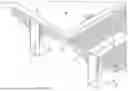
FIG. 1 is a perspective view of a deck tile support system employing joist straddling tile support planks forming a backing substrate for deck tiles with portions of the tiles broken away to show the support system.
FIG. 2 is a perspective, detail view of joist straddling tile support plank supported by a tube joist.
FIGS. 3A and 3B are perspective and end views respectively of a joist straddling tile support plank.
FIG. 4 is a perspective view of portions of a pair of joist straddling support planks and a tile where an edge or corner of the tile is aligned with a drainage gap between adjacent joist straddling support planks.
FIGS. 5A, 5B, and 5C, are perspective views of the assembly of a connector bridge extending into the drainage gap shown in FIG. 4.
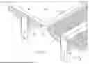
FIG. 6 is a perspective view of an embodiment of a deck tile support system employing tile support sister joists forming a backing substrate with the support joists of a deck frame for deck tiles.
FIG. 7 is a perspective view of a tile support sister joist shown in FIG. 6.
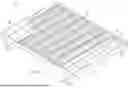
FIG. 8 is a perspective view of an alternate embodiment of a deck tile support system employing tile support straps running transverse to the support joists and forming a backing substrate for deck tiles according to the teachings of the present disclosure.
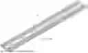
FIG. 9 is a perspective view of a tile support strap shown in FIG. 8.
FIG. 10 is a perspective view of an alternate embodiment of a deck tile support system employing tile support straps similar to those shown in FIG. 8 having a shorter width.
FIG. 11 is a perspective view of the tile support strap shown in FIG. 10.
FIG. 12A is a perspective view of an alternate embodiment of a deck tile support system employing tile support straps running transverse to the support joists and forming a backing substrate for deck tiles according to the teachings of the present disclosure with connector tabs extending from each vertical wall of the support strap.
FIG. 12B is a detailed view of abutting deck tiles support straps shown in FIG. 12A.
FIG. 13 is a perspective view of a deck tile support strap shown in FIG. 12A.
FIG. 14 is a perspective view of a deck tile support strap similar to that shown in FIG. 12A with connector tabs spaced to accommodate support joists that are spaced apart twelve inches on center.
FIG. 15 is a perspective view of a deck tile support strap similar to that shown in FIG. 14 with surface texture in the form of a pattern of through holes.
DETAILED DESCRIPTION
Embodiments disclosed herein provide systems and methods for supporting outdoor decks made of porcelain or stone tiles, bricks or other generally brittle material. The systems disclosed provide a backing substrate to which the deck tiles may be adhered. The backing substrate provides fall-through protection in the event of failure of the brittle pavers according to a generally known brittle failure mode.
FIG. 1 is a perspective view of a deck frame 10. The deck frame 10 supports a plurality of joist straddling tile support planks 12. Together, the deck frame 10 and the joist straddling tile support planks 12 make up a deck tile support system 11 according to the teachings of the present disclosure. More specifically, the joist straddling tile support planks 12 provide a backing substrate for the deck tiles 44 in that they provide a surface for adhesive and provide fall through protection in the event of a brittle failure.
The deck frame 10 may be a floating deck frame and includes four support post assemblies 14. The support post assemblies 14 directly support the perimeter joist support members 16. Four perimeter joist support members 16 form a simple rectangular floating deck frame 10. The perimeter joist support members 16 are coupled to a plurality of joist support brackets 18. A pair of joist support brackets 18 receive ends of a joist 20. The joists may be positioned approximately 12 or 16 inches on center. According to an embodiment, the joist support brackets 18 may also be used to support beams.
A deck frame suitable for use with the deck tile support system 11 is disclosed and claimed in U.S. Pat. No. 11,028,580 assigned to Fortress Iron LP and titled Deck Frame with Integral Attachment Tabs and filed on May 25, 2018, which is hereby incorporated by reference. The '580 patent discloses a deck frame that includes perimeter support members with integral tabs to which the support joists are attached. Another suitable deck frame for use with the present disclosure is described in U.S. Pat. No. 11,598,090, which is hereby incorporated by reference. The '090 patent discloses a deck frame with rectangular tube joists that receive joist support brackets that are connected to perimeter support members, for example an S-ledger. Embodiments disclosed herein may also be used with a variety of framing materials, such as traditional pressure treated wood, steel framing, aluminum framing, or composite framing.
A detailed perspective view of a support joist 20 and a joist straddling tile support plank 12 is shown in FIG. 2. The support joist 20 is generally in the form of a tube with open ends and a rectangular profile/cross-section. The tube joist 20 includes a top wall 22 and an opposed bottom wall 24. The tube joist 20 also includes a pair of opposed lateral walls 26. Other configurations of support joists are contemplated by this disclosure. When referring to support joists in this disclosure, this term is intended to encompass support beams unless otherwise indicated.
The joist straddling tile support plank 12 straddles the tube joist such that a portion of a top wall 28 of the joist straddling tile support plank 12 rests on the top wall 22 of the support joist 20. According to an embodiment, the joist straddling tile support plank 12 includes a pair of lateral walls 29 that abut the lateral walls 26 of the support joist 20. The lateral walls 29 maybe oriented generally vertically. The lateral walls 29 include sufficient surface area to allow a fastener, such as a self-drilling sheet metal screw to penetrate the lateral wall 29 and also penetrate the lateral wall 26 to join the joist straddling tile support plank 12 to the support joist 20.
FIG. 3A is a perspective view of an embodiment of the joist straddling tile support plank 12. FIG. 3B is an end view of the joist straddling tile support plank 12. As illustrated, the joist straddling tile support plank 12 extends a length that corresponds to the support joist 20 to which it is attached. With reference to FIG. 1, the joist straddling tile support plank 12 straddles each joist 20. In this manner, the deck frame 10 is provided with a generally continuous support surface suitable for supporting brittle walking surfaces, such as porcelain or stone tile. The top wall 28 includes a grooved surface 30. The grooved surface 30 facilitates attachment of the deck tiles 44 using adhesive 45, for example a liquid epoxy adhesive. The liquid epoxy may be applied to either the surface of the tile 44 or the grooved surface 30 or both. The grooved surface 30 allows the adhesive 45 to be received in the grooves and thereby maintain a stronger connection than if the adhesive was applied to a flat, non-grooved surface. This disclosure contemplates a flat, non-grooved surface embodiment of the joist straddling tile support planks.
The joist straddling tile support plank 12 also includes a ripping groove 32. The ripping groove 32 allows the separation of halves of the joist straddling tile support plank 12 in the event only one half is needed. As one example, the ripping groove 32 may be used to create a half the tile support plank 31 when the tile support plank 12 is attached to a perimeter joist support member 16, as shown in FIG. 1.
The joist straddling tile support plank 12 may be formed by known metal and polymeric forming techniques such as extrusion. Certain known after extrusion processes may be performed on the extruded part. According to certain embodiments, the tile support plank 12 may be formed by extruding a polymeric material, for example polyvinyl chloride (PVC). Alternatively, the joist straddling tile support planks 12 may be formed of extruded aluminum or other suitable metallic material.
With reference to FIG. 3B, a lower angled wall 34 extends from the lateral wall 29 at a nonperpendicular angle on each side of the joist straddling tile support plank 12. A plurality of internal horizontal walls 36 extend from the lower angled wall 34 horizontally toward the center of the joist straddling tile support plank 12. An end of the internal horizontal wall 36 includes a joist abutting portion 38. The joist abutting portion 38 increases the surface area of the internal horizontal wall 36 to provide additional contact area to contact the lateral wall 26 of the support joist 20. Alternatively, the joist abutting portions 38 of each internal horizontal wall 36 may be replaced with a continuous wall extending across multiple ends of the internal horizontal wall ends 36.
Reference is made to FIG. 4, which illustrates a gap 42 between a pair of adjacent joist straddling tile support planks 12, each straddling a respective support joist 20. According to certain embodiments, a width of the gap 42 between the planks 12 may be about two inches. The gap 42 facilitates drainage of rain water from the deck, and a two inch gap generally supports the tiles 44 forming the external surface of the deck without creating a fall-through risk in the event a tile fails according to a brittle failure mode.
In the event an edge or corner of a tile 44 is not supported by a support plank 12 and instead falls at a location of a gap 42, a connection bridge assembly 40 may connect adjacent joist straddling tile support planks 12 at specific locations and support a corner or edge of a paving tile 44 (see FIGS. 5B and 5C).
Reference is made to FIGS. 5A, 5B, and 5C, which show perspective views of stages of the assembly of the connection bridge assembly 40 that supports the edge or corner of the deck tiles 44.
It is understood that the terms deck tiles, tiles, or pavers refer to a variety of deck surfaces formed of generally brittle material that requires more support than traditional wood or wood composite deck surfaces. For example, the tile 44 may be a concrete paver, a stone paver, a porcelain or ceramic tiles, and the like.
Features of the joist straddling tile support planks 12 are configured to engage with corresponding features of a connection bridge assembly 40. For example, the joist straddling tile support planks 12 include a pair of plank channels 46 separated from each other by a plank projection 49. The plank channels 46 and the plank projection 49 run the length of the joist straddling tile support planks 12 and provide engagement features for a bridge support member 48. The bridge support member 48 may be injection molded PVC in the shape shown in FIG. 5A. The bridge support member 48 includes a pair of bridge projections 50 that are configured to be received by the plank channels 46. Similarly, the bridge support members 48 include a bridge channel 52 configured to receive the plank channel 46 extending from the joist straddling tile support planks 12. The bridge support members 48 also include a level wall 54 and a vertical wall 56. The bridge projections 50 extend from the vertical wall 56.
With the bridge support members 48 engaged with the joist straddling tile support planks 12, an upper surface 58 of the upper bridge projection 50 engages a corresponding surface 59 of the joist straddling deck support planks 12. A lower surface 60 of the lower bridge projection 50 engages a corresponding surface 61 of the joist straddling tile support planks 12. In this manner, the level wall 54 cantilevers into the gap 42 and is wedged in engagement with the joist straddling deck tile support planks 12. As shown in FIGS. 5A and 5B, a left support plank 12 supports a bridge support member 48 that extends to cover approximately half of the gap 42, and a second bridge support member 48 extends from a right deck joist straddling to cover approximately half of the width of the gap 42.
The bridge support members 48 include a pair of key-shaped projections 62 extending vertically upward from the level wall 54. The key-shaped projections 62 are configured to engage with corresponding channels 64 of a bridge 66. The bridge 66 may be a generally hollow box shaped component. As shown in FIG. 5B, the bridge 66 has a width of approximately 2 inches and is snap fit onto the key-shaped projections 62. According to an embodiment, a single bridge 66 is snap fit over a pair of bridge support members 48. FIG. 5B shows a perspective view of a partially assembled connection bridge assembly 40 with the bridge 66 shown exploded from the bridge support members 48. The bridge 66 may be cut to size from a larger length of extruded polymeric material, such as PVC. Alternatively, the bridge 66 may be formed from extruded aluminum or other suitable metal. The bridge 66 may be extruded substantially in the form shown in FIG. 5B in twelve foot lengths, which can be cut down to two inch bridges 66.
Reference is made to FIG. 5C, which shows an assembled connection bridge assembly supporting a tile 44 with a corner that is located at the gap 42 between the adjacent joist straddling tile support planks 12. The upper surface of the bridge 66 maybe coated with adhesive that is disposed between the upper surface of the bridge 66 and the tile 44 to adhere the tile 44 to the deck frame 10. The upper surface of the bridge 66 may be generally flush with the upper surface of the deck planks 12.
Reference is made to FIG. 6, which is a perspective view of and embodiment of a deck tile support system 70. The deck tile support system 70 includes the deck frame 10 as described above with respect to FIG. 1 including the perimeter members 16 and the support joists 20. The deck tile support system 70 includes a plurality of tile support sister joists 72. More specifically, the support joists 20 and the tile support sister joists 72 together provide a backing substrate for the deck tiles 44. The backing surface provides a substantially continuous surface for adhesive and provides fall through protection in the event of a brittle failure of the supported deck tiles.
A pair of tile support sister joists 72 is generally attached to each of the support joists 20. A tile support sister joist 72 is also attached to two of the perimeter members 16 (only one shown). The attachment of the sister joist 72 to the support joist 20 and the perimeter member 16 form a surface on which tiles may be secured. The layout of the tile support sister joists 72 create drainage gaps 74 between adjacent tile support sister joists 72 as shown in FIG. 6. Sheet metal fasteners, such as self-drilling sheet metal screws are used to secure the tiles support sister joist 72 to the lateral wall of the joists 20, as discussed further below.
Reference is made to FIG. 7, which is a perspective view of a tile support sister joist 72. The tile supports sister joist 72 includes an upper, horizontal wall 76 and a plurality of vertical walls 78. Support tabs 80 are cut from a continuous wall and bent approximately 90° to form tabs 80 that support the upper horizontal wall 76. According to certain embodiments, each one of the support tabs 80 may include one or more through holes 82. The locations in the vertical wall 78 where the support tabs 80 are cut from form voids 83 in the continuous wall and thereby form the vertical walls 78. The support tabs 80 may also be used to support blocking of the deck frame in that a piece of joist may be cut and secured to the support tabs to add an additional joist piece to which a post or other deck feature may be attached. This blocking also functions as a stiffening member.
Returning to FIG. 6, the tile support sister joist 72 is positioned such that the upper surface of the upper horizontal wall 76 is flush with the upper surface of the joist 20 and the upper horizontal wall 76 runs parallel to the joist 20. In this configuration, fasteners (not shown) may be inserted through the vertical walls 78 and into the lateral walls of the joist 20. According to an alternate embodiment, the vertical walls 78 may be magnetized such that the magnetic force holds the vertical wall 78 to abut the lateral wall of the joist 20.
One sister joist 72 is secured to one lateral wall of a joist 20 and a second sister joist 72 is secured to the opposite lateral wall of the same joist 20 and thereby form a substantially flat surface which can receive adhesive to allow the tiles 44 to be secured to the surface of the deck tile support system 70.
Each of the tile support sister joists may be formed of 18 gauge steel. For example, each tile support sister joist 72 may be a sheet metal blank that is cut and sheet-metal formed into the configuration shown in FIG. 7. The specific material may be Q195, G60, 18 Gage carbon steel. Alternatively, Q235 steel may be used.
According to an embodiment, the upper wall may have a width of approximately 5 inches. This 5 inch with is particularly suited to form the tile support surface with joists 20 that are positioned at 12 inches on center to form a drainage gap 74 of approximately 0.25 inches.
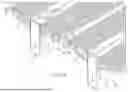
Reference is made to FIG. 8, which is a perspective view of a deck tile support system 90 employing tile support straps 92, and FIG. 9, which is a perspective view of a deck tile support strap 92. FIG. 8 shows twenty-two support straps 92 secured to joists 20 of the deck frame 10. The tile support straps 92 straddle the joists and run transverse to the length of the support joists 20. The tile support straps 92 provide a backing substrate for the deck tiles 44. The backing surface provides a substantially continuous surface for adhesive and provides fall through protection in the event of a brittle failure of the supported deck tiles 44.
Each of the tile support straps 92 has a length 94 to accommodate and be secured to four support joists 20 that are positioned 16 inches on center. For example, the length 94 may be approximately 48 inches. The tile supports straps 92 have a width 96 of approximately 6 inches. When the tile support straps 92 are laid across the 16 inch on-center joists, they provide a tile support surface that can receive adhesive to secure a plurality of tiles 44 to the support surface. In addition, the tile support straps 92 are spaced such that a drainage gap of up to approximately 2 inches is disposed perpendicular to the joists 20. Alternatively, the support straps 92 may abut each other, such that there is no substantial drainage gap between adjacent support straps 92.
FIG. 9 is a perspective view of a tile support strap 92. Each of the tile support straps 92 may be formed by metal forming techniques used to form a piece of sheet metal. For example, the sheet metal may be 18 gauge steel. The tile support straps 92 include an upper horizontal wall 98 and a plurality of vertical walls 100 extending perpendicular to the horizontal wall. A plurality of connector tabs 102 is cut from the vertical walls 100 and bent approximately 90° with respect to the vertical walls 100. The displacement of the connector tabs 102 create gaps 104 that are sized to receive the width of the joists 20. The connector tabs 102 have a length that serves as a spacing guide for the position of the next adjacent strap and to allow for drainage. When the tile support straps 92 are placed over the joists 20, the connector tabs 102 are positioned on one side of the joist 20. A self-drilling fastener, such as a self-drilling sheet metal screw is inserted through the connector tab 102 and into a lateral wall of the support joist 20. According to an embodiment, the connector tab 102 includes a predrilled through hole 119 to receive the self-drilling fastener.
Reference is made to FIG. 10, which shows an alternate embodiment of the tile support straps, where the width 99 of the tile support straps is approximately 4 inches (see FIG. 11). The tile support straps 110 include the same features as the tile support straps 92 shown in FIGS. 8 and 9. The width 99 of four inches causes the deck frame shown in FIG. 10 to support twenty-eight tile support straps. The tile support straps 110 straddle the joists and run transverse to the length of the support joists 20. The tile support straps 110 provide a backing substrate for the deck tiles 44. The backing surface provides a substantially continuous surface for adhesive and provides fall through protection in the event of a brittle failure of the supported deck tiles 44. The backing surface provides a substantially continuous surface for adhesive and provides fall through protection in the event of a brittle failure of the supported deck tiles 44. Similar to the embodiment shown in FIGS. 8 and 9, the upper horizontal wall 98 of the tile support straps form a surface to receive adhesive and the tiles 44 may be thereby secured with the adhesive to the deck tile support system 90. FIG. 11 is a perspective view of a tile support strap 110 showing the features described with respect to FIG. 9.
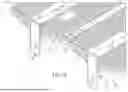
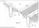
FIG. 12 is a perspective view of an alternate embodiment of a deck tile support system 118 that includes a plurality of offset tabbed tile support straps 120. FIG. 13 is a perspective view of the offset tabbed tile support strap 120. FIG. 12 shows eight offset tabbed tile support straps supported by four support joists 20. The offset tabbed tile support straps 120 provide a backing substrate for deck tiles 44 (see FIG. 8) to be adhered to the offset tabbed tile support straps 120. The offset tabbed tile support straps lay transversely across four joists 20 and include many of the same features shown and described with respect to FIGS. 8 and 9, with the exception that the offset deck tile support strap 120 includes connector tabs 132 extending from both sides of the offset tabbed tile support strap 120, as shown in FIG. 13. Also, the connector tabs 132 are offset to allow one connector tab 132 to be secured to one lateral wall of the support joist 20 and the offset and opposite connector tab 132 is secured to the other lateral wall of the same support joist 20. The tile support straps 120 provide a backing substrate for the deck tiles 44. The backing surface provides a substantially continuous surface for adhesive and provides fall through protection in the event of a brittle failure of the supported deck tiles 44.
As shown in FIG. 12A, the spacing between adjacent offset tabbed tile support straps 120 may vary. For example, an installer may use the connector tabs 132 to provide the spacing of adjacent tile support straps as shown in FIG. 8. Alternatively, the connector tabs may be nested in a gap 134 of an adjacent offset tabbed tile support strap 120 such that the adjacent tile support straps 120 substantially abut each other.
FIG. 12B is a detail of abutting tile support straps 120a and 120b. As shown, connector tab 132b is received in gap 134 of tile support strap 120a. Similarly, connector tab 132a is received in gap 134 of tile support strap 120b.
Reference is made to FIG. 13, which is a perspective view of an offset tabbed tile support strap 120. The tile support strap 120 has a length 124 to accommodate and be secured to four support joists 20 that are positioned 16 inches on center. For example, the length 124 may be approximately 48 inches. The tile supports straps 120 have a width 126 of approximately 6 inches. When the tile support straps 120 are laid across the 16 inch on-center joists, they provide a tile support surface that can receive adhesive to secure a plurality of tiles 44 to the support surface. In addition, the tile support straps 120 may be spaced such that a drainage gap of up to approximately 2 inches is disposed perpendicular to the joists 20. Alternatively, the support straps 92 may abut each other, such that there is no substantial drainage gap between adjacent support straps 92 (see FIGS. 12A and 12B). The connector tab spacing 136 accommodates 16 inch on center joists 20.
FIG. 13 is a perspective view of a tile support strap 120. The tile support straps 120 may be formed by metal forming techniques used to form a piece of sheet metal. For example, the sheet metal may be 18 gauge steel. The tile support straps 120 include a upper horizontal wall 128 and a plurality of vertical walls 130 extending perpendicular to the horizontal wall 128. A plurality of connector tabs 132 is cut from the vertical walls 130 and bent approximately 90° with respect to the vertical walls 130. The displacement of the connector tabs 132 create gaps 134 that are sized to receive the width of the joists 20. The connector tabs 132 have a length that may serve as a spacing guide for the position of the next adjacent strap and to allow for drainage. When the tile support straps 120 are placed over the joists 20, the connector tabs 132 are positioned on both sides of the joist 20. A self-drilling fastener, such as a self-drilling sheet metal screw is inserted through the connector tab 132 and into a lateral wall of the support joist 20. According to an embodiment, the connector tab 132 includes a predrilled through hole 133 to receive the self-drilling fastener.
Reference is made to FIG. 14, which shows an alternate embodiment of the tile support straps, where the tabbed spacing 142 accommodates 12 inch on center joists 20. The other features are similar to those described above with respect to FIG. 13, and therefore will not be repeated.
Reference is made to FIG. 15, which shows an alternate embodiment of a tile support strap 150 that includes a plurality of through holes 152 extending through the upper horizontal wall 154. The through holes 152 may be any suitable size, such as ⅛ inch in diameter. The through holes 152 permit water drainage to prevent rainwater or other water accumulation between the deck tiles and the tile support strap 150. Additionally, the through holes 152 allow an adhesive to flow through and set within the through holes 152. In this manner, additional surface area of the tiles support strap 150 is adhered to a deck tile. The tile support strap 150 may include through holes in any suitable pattern, such as the rows and columns of through holes 152 shown in FIG. 15. Other types of surface texture that provides additional surface area to allow an adhesive to bond to the surface texture may be include on the upper horizontal wall 154 of the tile support strap 150 (see FIGS. 3A-3B). Similar to the tile support strap illustrated in FIG. 14, the spacing of the connector tabs 156 accommodates support joists 20 positioned 12-inches on center. The other features of the tile support strap 150 are similar to those described above with respect to FIG. 13, and therefore will not be repeated.
As used herein, the terms “approximately,” “about,” “substantially”, and similar terms are intended to have a broad meaning in harmony with the common and accepted usage by those of ordinary skill in the art to which the subject matter of this disclosure pertains. It should be understood by those of skill in the art who review this disclosure that these terms are intended to allow a description of certain features described and claimed without restricting the scope of these features to the precise numerical ranges provided. Accordingly, these terms should be interpreted as indicating that insubstantial or inconsequential modifications or alterations of the subject matter described and claimed are considered to be within the scope of the disclosure as recited in the appended claims.
It should be noted that the term “exemplary” and variations thereof, as used herein to describe various embodiments, are intended to indicate that such embodiments are possible examples, representations, or illustrations of possible embodiments (and such terms are not intended to connote that such embodiments are necessarily extraordinary or superlative examples).
The term “or,” as used herein, is used in its inclusive sense (and not in its exclusive sense) so that when used to connect a list of elements, the term “or” means one, some, or all of the elements in the list. Conjunctive language such as the phrase “at least one of X, Y, and Z,” unless specifically stated otherwise, is understood to convey that an element may be either X, Y, Z; X and Y; X and Z; Y and Z; or X, Y, and Z (i.e., any combination of X, Y, and Z). Thus, such conjunctive language is not generally intended to imply that certain embodiments require at least one of X, at least one of Y, and at least one of Z to each be present, unless otherwise indicated.
References herein to the positions of elements (e.g., “top,” “bottom,” “above,” “below”) are merely used to describe the orientation of various elements in the figures. It should be noted that the orientation of various elements may differ according to other exemplary embodiments, and that such variations are intended to be encompassed by the present disclosure.
Although the figures and description may illustrate a specific order of method steps, the order of such steps may differ from what is described, unless specified differently above. Also, two or more steps may be performed concurrently or with partial concurrence, unless specified differently above. All such variations are within the scope of the disclosure.
It is important to note that the construction and arrangement of the assemblies as shown in the various exemplary embodiments is illustrative only. Additionally, any element disclosed in one embodiment may be incorporated or utilized with any other embodiment disclosed herein. Although only one example of an element from one embodiment that can be incorporated or utilized in another embodiment has been described above, it should be appreciated that other elements of the various embodiments may be incorporated or utilized with any of the other embodiments disclosed herein.
Claims
What is claimed is:1. A deck tile support system, comprising:
a deck frame comprising at least one perimeter support member supporting a plurality of support joists, each support joist comprising a top wall and at least one lateral wall extending downwardly from the top wall; and
a plurality of deck tile support straps secured to the plurality of support joists, the plurality of deck tile support straps together forming a backing substrate supporting a plurality of deck tiles, each deck tile support strap comprising:
a horizontal wall;
a first vertical wall defining a plurality of first gaps each receiving one of the plurality of support joists;
a second vertical wall defining a plurality of second gaps each receiving the one of the plurality of support joists; and
a plurality of first connector tabs extending generally perpendicularly from the first vertical wall and secured to the at least one lateral wall of respective ones of the plurality of support joists.
2. The deck tile support system of claim 1 wherein each deck tile support strap further comprises a plurality of second connector tabs extending generally perpendicularly from the second vertical wall and secured to a second lateral wall of respective ones of the plurality of support joists opposite the at least one lateral wall.
3. The deck tile support system of claim 1 wherein at least one of the plurality of deck tile support straps straddles multiple ones of the plurality of support joists.
4. The deck tile support system of claim 3 wherein at least one of the plurality of deck tile support straps runs transverse to at least one of the plurality of support joists.
5. The deck tile support system of claim 1 wherein each of the plurality of deck tile support straps is formed of metal.
6. The deck tile support system of claim 1 wherein each of the plurality of deck tile support straps is formed of a polymeric material.
7. The deck tile support system of claim 1 wherein each of the plurality of deck tiles is porcelain.
8. The deck tile support system of claim 1 wherein each of the plurality of deck tiles is stone.
9. The deck tile support system of claim 1 wherein each of the plurality of deck tiles is brick.
10. The deck tile support system of claim 1 further comprising a gap between adjacent deck tile support straps.
11. The deck tile support system of claim 10 wherein the gap is less than two inches.
12. The deck tile support system of claim 1 wherein a first one of the plurality of deck tile support straps abuts a second one of the plurality of deck tile support straps.
13. The deck tile support system of claim 1 wherein the plurality of deck tiles is adhered to the plurality of deck tile support straps.
14. The deck tile support system of claim 1 wherein the plurality of support joists is spaced apart either 12 inches on center or 16 inches on center.
15. The deck tile support system of claim 1 wherein the horizontal wall defines a plurality of through holes.
16. A deck tile support system, comprising:
a deck frame comprising at least one perimeter support member supporting first and second support joists, each of the first and second support joists comprising a top wall and at least one lateral wall extending downwardly from the top wall; and
first and second deck tile support straps secured to the first and second support joists, the first and second deck tile support straps together forming a backing substrate configured to support a plurality of deck tiles, each of the first and second deck tile support straps comprising:
an upper horizontal wall;
a first vertical wall defining a first gap receiving the first support joist and a second gap receiving the second support joist;
a second vertical wall defining a third gap receiving the first support joist and a fourth gap receiving the second support joist;
a first connector tab extending generally perpendicularly from the first vertical wall and secured to the at least one lateral wall of the first support joist; and
a second connector tab extending generally perpendicularly from the first vertical wall and secured to the at least one lateral wall of the second support joist.
17. The deck tile support system of claim 16 wherein each of the first and second deck tile support straps further comprises:
a third connector tab extending generally perpendicularly from the second vertical wall and secured to a second lateral wall opposite the at least one lateral wall of the first support joist; and
a fourth connector tab extending generally perpendicularly from the second vertical wall and secured to a second lateral wall opposite the at least one lateral wall of the second support joist.
18. A deck tile support system, comprising:
a deck frame comprising at least one perimeter support member supporting first and second support joists, each of the first and second support joists comprising a top wall and at least one lateral wall extending downwardly from the top wall; and
first and second deck tile support straps secured to the first and second support joists, the first and second deck tile support straps together forming a backing substrate configured to support a plurality of deck tiles, each of the first and second deck tile support straps being formed of metal and comprising:
an upper horizontal wall defining a plurality of through holes;
a first vertical wall defining a first gap receiving the first support joist and a second gap receiving the second support joist;
a second vertical wall defining a third gap receiving the first support joist and a fourth gap receiving the second support joist;
a first connector tab extending generally perpendicularly from the first vertical wall and secured to the at least one lateral wall of the first support joist;
a second connector tab extending generally perpendicularly from the first vertical wall and secured to the at least one lateral wall of the second support joist;
a third connector tab extending generally perpendicularly from the second vertical wall and secured to a second lateral wall opposite the at least one lateral wall of the first support joist; and
a fourth connector tab extending generally perpendicularly from the second vertical wall and secured to a second lateral wall opposite the at least one lateral wall of the second support joist.
19. The deck tile support system of claim 18 further comprising a gap disposed between the first deck tile support strap and the second deck tile support strap.
20. The deck tile support system of claim 18 wherein the first deck tile support strap is abutted with the second deck tile support strap.
Images & Drawings included:


Sources:
- United States Patent and Trademark Office - verify current appl. status at the USPTO↗
Recent applications in this class:
- » 20250223791 2025-07-10
DECK CONSTRUCTION SYSTEM - » 20240392555 2024-11-28
Elevating Platform Device - » 20240287785 2024-08-29
BALCONY BOX - » 20240191493 2024-06-13
LEDGER BOARD SYSTEM - » 20240052623 2024-02-15
BUILDING - » 20240035269 2024-02-01
MODULAR BALCONY SYSTEM, COMPONENTS THEREOF AND METHOD OF ASSEMBLY AND INSTALLATION THEREOF - » 20240026675 2024-01-25
Decking System - » 20230417040 2023-12-28
A BALCONY - » 20230358029 2023-11-09
BALCONY - » 20230349144 2023-11-02
DOVETAIL DECKING SYSTEM WITH A FULL TOP FLANGE SIDELAP AND METHOD OF SECURING
Recent applications for this Assignee:
- » 20250257575 2025-08-14
RAILING POST BLOCKING SYSTEMS AND METHODS - » 20250207405 2025-06-26
REINFORCED ADJUSTABLE STAIR TRAY - » 20250146324 2025-05-08
USER ASSEMBLABLE PICKET RAIL PANEL - » 20250146292 2025-05-08
ADJUSTABLE STAIR RAILING POST ASSEMBLY - » 20250146291 2025-05-08
VERTICAL CABLE BARRIER HAVING RAILS WITH INTERNAL CABLE FITTING ENGAGEMENT FEATURES - » 20250052088 2025-02-13
VERTICAL CABLE RAIL BARRIER - » 20250027319 2025-01-23
BRACKET FOR SUPPORTING ATTACHMENT OF THE END OF A RAILING MEMBER TO A VERTICAL MEMBER - » 20240426102 2024-12-26
DECK FRAME WITH INTEGRAL ATTACHMENT TABS - » 20240301717 2024-09-12
RAKING BARRIER PANEL - » 20240125127 2024-04-18
TOGGLE BOLT CONNECTOR SYSTEM FOR HOLLOW JOIST