EXERCISE MACHINE
US20250288853A1
2025-09-18
18/604,430
2024-03-13
Smart Summary: An exercise machine consists of a main body with a base and a standing pole. It has two operating rods that are connected to pivoting joints on the standing pole. A resistance unit includes a driving wheel and a passive wheel that work together to create resistance. Each pedaling member has a pedal pole with pedals, which are attached to the operating rods. This design allows users to exercise by pushing down on the pedals while the machine provides resistance. 🚀 TL;DR
Abstract:
An exercise machine has a main body, two operating rods, a resistance unit, and two pedaling members. The main body has a base and a standing pole, two sides of the standing pole are both respectively pivoted with a pivoting joint, each pivoting joint having a through aperture for accepting one of the operating rods, a supporting frame installed between the standing pole and the base. Each operating rod is connected to the pivoting joints. The resistance unit has a driving wheel, a passive wheel, and a transmission member coupling the driving wheel to the passive wheel. Each pedaling member comprises a pedal pole, a first connecting rod, and a second connecting rod, the pedal pole is attached to a lower end of one of the operating rods and has a pedal at one end and another end pivoted onto the main body via a pivoting connector.
Applicant:
Interested in similar patents?
Get notified when new applications in this technology area are published.
Classification:
A63B21/225 » CPC main
Exercising apparatus for developing or strengthening the muscles or joints of the body by working against a counterforce, with or without measuring devices; Resisting devices with rotary bodies with flywheels
A63B22/001 » CPC further
Exercising apparatus specially adapted for conditioning the cardio-vascular system, for training agility or co-ordination of movements involving an exercising of arms by simultaneously exercising arms and legs, e.g. diagonally in anti-phase
A63B2022/0676 » CPC further
Exercising apparatus specially adapted for conditioning the cardio-vascular system, for training agility or co-ordination of movements with rotating cycling movement, performing an elliptic movement with crank and handles being on the same side of the exercising apparatus with respect to the frontal body-plane of the user, e.g. crank and handles are in front of the user
A63B21/22 IPC
Exercising apparatus for developing or strengthening the muscles or joints of the body by working against a counterforce, with or without measuring devices Resisting devices with rotary bodies
A63B22/00 IPC
Exercising apparatus specially adapted for conditioning the cardio-vascular system, for training agility or co-ordination of movements
A63B22/06 IPC
Exercising apparatus specially adapted for conditioning the cardio-vascular system, for training agility or co-ordination of movements with rotating cycling movement,
Description
BACKGROUND OF THE INVENTION
1. Field of Invention
The present invention relates to an exercise machine.
2. Description of the Related Art
Modern life people are busy with work and live at a fast pace. The focus of their life is mainly on work and family, and they rarely have time to exercise. As a result, weight gain and poor health are the common problems. However, going to the gym for exercise, time and space might also become issues. Therefore, many home exercise machines such as bikes, the flywheel, treadmills, and sliders . . . etc. various fitness equipment are developed.
Therefore, if an exercise machine that is lightweight and does not take up too much indoor space, users can exercise at home without being restricted by time or space. The structure of the exercise machine is relatively simple and uncomplicated, and can be purchased by ordinary families. The exercise machine can also provide muscle exercise to consume excess calories, allowing the user to maintain a healthy and light body.
Therefore, it is desirable to provide an exercise machine to mitigate and/or obviate the aforementioned problems.
SUMMARY OF THE INVENTION
An objective of present invention is to provide an exercise machine, which is capable of improving the above-mention problems.
In order to achieve the above-mentioned objective, an exercise machine, has a main body, two operating rods, a resistance unit, and two pedaling members. The main body has a base and a standing pole, two sides of the standing pole are both respectively pivoted with a pivoting joint, each pivoting joint having a through aperture for accepting one of the operating rods, a supporting frame installed between the standing pole and the base. Each operating rod has a handle and is inserted in one of the through apertures to be connected to one of the pivoting joints, a lower end of each operating rod being attached to one of the pedaling members. The resistance unit has a driving wheel, a passive wheel, and a transmission member coupling the driving wheel to the passive wheel, the driving wheel and the passive wheel respectively mounted in the main body via a driving wheel axis and a passive wheel axis, and a flywheel is coaxially installed with the passive wheel. The driving wheel drives the flywheel to rotate via the transmission member and the passive wheel; and wherein the resistance unit further has a magnetic member pivoted on the main body configured to passively generate different resistances to the flywheel and the pedaling member. Each pedaling member has a pedal pole, a first connecting rod, and a second connecting rod, the pedal pole attached to a lower end of one of the operating rods and has a pedal at one end and another end pivoted onto the main body via a pivoting connector, and the first connecting rod is installed between the pedal pole and the second connecting rod. A free end of the second connecting rod is secured onto the driving wheel axis, such that the pedals of the two pedaling members are configured to drive the driving wheel via the first connecting rod and the second connecting rod.
Other objects, advantages, and novel features of invention will become more apparent from the following detailed description when taken in conjunction with the accompanying drawings.
BRIEF DESCRIPTION OF THE DRAWINGS
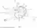
FIG. 1 is a three-dimensional combination view of a preferred embodiment according to the present invention.
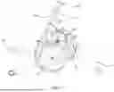
FIG. 2 is a three-dimensional exploded view of the preferred embodiment according to the present invention.
FIG. 3: is a detailed exploded view of the preferred embodiment according to the present invention.
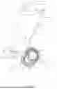
FIG. 4 is a combined cross-sectional view of the preferred embodiment according to the present invention.
FIG. 5 is a partial enlarged view of the combined section of the preferred embodiment according to the present invention.
FIG. 6 is a partial enlarged view of the combined section of the preferred embodiment according to the present invention.
FIG. 7 is a fitness state diagram of the preferred embodiment according to the present invention.
DETAILED DESCRIPTION OF PREFERRED EMBODIMENT
First, please refer to FIGS. 1 to 6. An exercise machine, comprises a main body 10, two operating rods 20, a resistance unit 30 and two pedaling members 40. The main body 10 comprises a base 11 and a standing pole 12, two sides of the standing pole 12 are both respectively pivoted with a pivoting joint 13.
Each pivoting joint 13 has a through aperture 131 for accepting one of operating rod 20, and a supporting frame 14 is installed between the standing pole 12 and the base 11.
The operating rod 20 comprises a handle 21 and is inserted in one of the through aperture 131 to be connected to one of the pivoting joint 13. A lower end of each operating rod 20 is attached to one of the pedaling member 40. The resistance unit 30 comprises a driving wheel 31, a passive wheel 32 and a transmission member 33 coupling the driving wheel 31 to the passive wheel 32.
The driving wheel 31 and the passive wheel 32 are respectively mounted in the main body 10 via a driving wheel axis 34 and a passive wheel axis 35.
Furthermore, a flywheel 36 is coaxially installed with the passive wheel 32, when the driving wheel 31 drives the flywheel 36 to rotate via the transmission member 33 and the passive wheel 32.
Moreover, the resistance unit 30 further comprises a magnetic member 37 pivoted on the main body 10 configured to passively generate different resistances to the flywheel 37 and the pedaling member 40 due to the distance between the magnetic member 37 and the flywheel 36 controlled by external force.
The pedaling member 40 has a pedal pole 41, a first connecting rod 42 and a second connecting rod 43. The pedal pole 41 is attached to a lower end of one of the operating rod 20 and has a pedal 411 at one end and another end pivoted onto the main body 10 via a pivoting connector 44. The first connecting rod 42 is installed between the pedal pole 41 and the second connecting rod 43. A free end of the second connecting rod 41 is secured onto the driving wheel axis 34, such that the pedals 411 of the two pedaling members 40 are configured to drive the driving wheel 31 via the first connecting rod 42 and the second connecting rod 43.
In addition, the base 11 has an H-shaped structure.
Also, the main body 10 further comprises two housings 15 for covering the resistance unit 30.
Furthermore, a horizontal rod 16 is placed and secured between the pivoting joint 13 and the standing pole 12 to connect the pivoting joint 13 to the standing pole 13.
Moreover, the standing pole 12 further comprises a armrest 17 and a control panel 18.
Additionally, a resistance controller 19 is provided on the standing pole 12. The resistance controller 19 is connected to the magnetic member 37 through a cable, so that through the rotation of the resistance controller 19, and the magnetic member 37 can be driven close to or away from the flywheel 36 through the cable.
Again, a length of each operating rod 20 is adjustable.
Additionally, the transmission member 33 comprises a belt and an idler 38 for adjusting a tightness of the belt.
Furthermore, the driving wheel axis 34 and the passive wheel axis 35 are respectively installed on the base 11 and the supporting frame 14.
In addition, for each pedaling member 40, the pedal pole 41, the first connecting rod 42 and the second connecting rod 43 are connected among each other such that the first connecting rod 42 is configured to rotate at a middle section of the pedal pole 41.
As shown in FIG. 7, when it is actually used, the two pedals 411 are stepped on alternately, and the pivoting connector 44 is used as the pivot point to drive the driving wheel 31 through the first connecting rod 42 and the second connecting rod 43.
During the pedaling process of the pedals 411, the pedal pole 41 also drives the operating rod 20 pivoted at the pivoting joint 13 to perform a back-and-forth swing, which allows the hands holding the handle 21 to be pushed and pulled forward and backward by the operating rod 20 to fully extend the limbs.
Therefore, the exercise machine provides full-body exercise, so the fitness effect is very satisfying. By lifting the hands up and moving forward and backward, symptoms such as frozen shoulder and arthritis can also be prevented and improved. Moreover, the exercise machine of the present invention does not need too much space, and the structure is relatively simple not complicated, so it is very suitable for common families to purchase in order to exercise at any time.
Although the present invention has been explained in relation to its preferred embodiment, it is to be understood that many other possible modifications and variations can be made without departing from the spirit and scope of invention as hereinafter claimed.
Claims
What is claimed is:1. An exercise machine, comprising: a main body, two operating rods, a resistance unit, and two pedaling members, wherein:
the main body comprises a base and a standing pole, two sides of the standing pole are both respectively pivoted with a pivoting joint, each pivoting joint having a through aperture for accepting one of the operating rods, a supporting frame installed between the standing pole and the base;
each operating rod comprises a handle and is inserted in one of the through apertures to be connected to one of the pivoting joints, a lower end of each operating rod being attached to one of the pedaling members;
the resistance unit comprises a driving wheel, a passive wheel, and a transmission member coupling the driving wheel to the passive wheel, the driving wheel and the passive wheel respectively mounted in the main body via a driving wheel axis and a passive wheel axis, and a flywheel is coaxially installed with the passive wheel; wherein the driving wheel drives the flywheel to rotate via the transmission member and the passive wheel; and wherein the resistance unit further comprises a magnetic member pivoted on the main body configured to passively generate different resistances to the flywheel and the pedaling member; and
each pedaling member comprises a pedal pole, a first connecting rod, and a second connecting rod, the pedal pole attached to a lower end of one of the operating rods and has a pedal at one end and another end pivoted onto the main body via a pivoting connector, and the first connecting rod is installed between the pedal pole and the second connecting rod; wherein a free end of the second connecting rod is secured onto the driving wheel axis, such that the pedals of the two pedaling members are configured to drive the driving wheel via the first connecting rod and the second connecting rod.
2. The exercise machine as claimed in claim 1, wherein the base has an H-shaped structure.
3. The exercise machine as claimed in claim 1, wherein the main body further comprises two housings for covering the resistance unit.
4. The exercise machine as claimed in claim 1, wherein a horizontal rod is placed and secured between the pivoting joint and the standing pole to connect the pivoting joint to the standing pole.
5. The exercise machine as claimed in claim 1, wherein the standing pole further comprises an armrest and a control panel.
6. The exercise machine as claimed in claim 1, wherein a length of each operating rod is adjustable.
7. The exercise machine as claimed in claim 1, wherein the transmission member comprises a belt and an idler for adjusting a tightness of the belt.
8. The exercise machine as claimed in claim 1, wherein the driving wheel axis and the passive wheel axis are respectively installed on the base and the supporting frame.
9. The exercise machine as claimed in claim 1, wherein for each pedaling member, the pedal pole, the first connecting rod and the second connecting rod are connected among each other such that the first connecting rod is configured to rotate at a middle section of the pedal pole.
Images & Drawings included:


Sources:
- United States Patent and Trademark Office - verify current appl. status at the USPTO↗
Similar patent applications:
- » 20240293697
EXERCISE MACHINES, CRANKSHAFT ASSEMBLIES FOR EXERCISE MACHINES, AND METHODS OF DISASSEMBLING EXERCISE MACHINES HAVING CRANK ARMS - » 20140135181
Cable end assemblies for exercise machines, exercise machines including such cable end assemblies, and related methods - » 20140121072
Hook assemblies for exercise machines, exercise machines including such hook assemblies, and related methods - » 20200384316
Method of unlocking a control unit of an exercise machine and exercise machine implementing such method - » 20220305338
METHOD FOR CONTROLLING A USER'S BREATHING DURING A WORKOUT WITH AN EXERCISE MACHINE AND EXERCISE MACHINE THEREOF - » 20230124164
METHOD FOR ESTIMATING A MAXIMUM POWER VALUE GENERATABLE BY A USER DURING A RESISTANCE TRAINING EXERCISE ON AN EXERCISE MACHINE AND EXERCISE MACHINE ABLE TO IMPLEMENT SAID METHOD - » 20210193115
METHOD FOR IMPROVING THE USER TRAINING EXPERIENCE ON AN EXERCISE MACHINE AND EXERCISE MACHINE IMPLEMENTING SUCH METHOD - » 20220134186
METHOD FOR CONTROLLING EXERCISE LOAD VARIATIONS IN A STRENGTH EXERCISE MACHINE AND EXERCISE MACHINE IMPLEMENTING SUCH METHOD - » 20210125698
Auto log-out from an exercise machine in an exercise machine monitoring system - » 12661710
Abdominal swiveling exercise machine combined with an elliptical trainer exercise machine, or skate simulation trainer, or exercise bicycle or recumbent bicycle
Recent applications in this class:
- » 20250073524 2025-03-06
FREEWHEEL ADJUSTABLE WHEEL AND FITNESS BIKE THEREWITH - » 20250041651 2025-02-06
Exercise Bike Flywheel System - » 20250010127 2025-01-09
SMART TORQUE SIMULATION DEVICE - » 20250001238 2025-01-02
FITNESS BIKE AND CONTROLLING METHOD THEREOF - » 20230414990 2023-12-28
Exercise Device And Exercise System - » 20230256293 2023-08-17
Wind resistance type spinning bike - » 20230028141 2023-01-26
TREMOR STABILISATION APPARATUS - » 20220347515 2022-11-03
Exercise machines having synchronizing clutch mechanism - » 20220266085 2022-08-25
Strength training apparatus - » 20220047909 2022-02-17
Fly wheel resistance workout system