SCREED BAR ADAPTER
US20250290331A1
2025-09-18
19/073,865
2025-03-07
Smart Summary: A vibrating concrete screed helps to level and smooth concrete surfaces. It has a frame and a motor that makes it vibrate. The device includes a part called an excitor assembly that holds a first screed bar. An adapter is used to connect this excitor assembly to another screed bar. This setup allows for different screed bars to be easily attached and used for various concrete jobs. 🚀 TL;DR
Abstract:
A vibrating concrete screed including: a frame; a motor coupled to the frame; an excitor assembly driven by the motor and including a first clamp assembly for coupling a first screed bar having a first configuration; a screed bar adapter configured to be coupled to the excitor assembly by the first clamp assembly, the screed bar adapter having a second clamp assembly; and a screed bar configured to be received by the second clamp assembly on the screed bar adapter.
Inventors:
- Ian C. Richards 9 🇺🇸 Shorewood, WI, United States
- Mason B. Lehman 1 🇺🇸 South Whitley, IN, United States
Applicant:
Interested in similar patents?
Get notified when new applications in this technology area are published.
Classification:
E04F21/242 » CPC main
Implements for finishing work on buildings for laying flooring of masses made , e.g. smoothing tools; Elongated smoothing blades or plates, e.g. screed apparatus with vibrating means, e.g. vibrating screeds
E04F21/24 IPC
Implements for finishing work on buildings for laying flooring of masses made , e.g. smoothing tools
Description
CROSS-REFERENCE TO RELATED APPLICATIONS
This application claims priority to U.S. Provisional Patent Application No. 63/675,437, filed on Jul. 25, 2024, and U.S. Provisional Patent Application No. 63/564,728, filed on Mar. 13, 2024, the entire contents of both of which are incorporated herein by reference.
FIELD OF THE DISCLOSURE
The present disclosure relates to concrete finishing tools, and more particularly to adapters for screed bars.
BACKGROUND OF THE DISCLOSURE
When installing concrete pads or foundations, it is necessary to level the surface of the concrete before finishing the of the concrete. For example, tools such as concrete screeds are used to level the concrete. Improvements in these tools are always sought by the industry.
SUMMARY OF THE DISCLOSURE
In some aspects, the techniques described herein relate to a vibrating concrete screed including: a frame; a motor coupled to the frame; an excitor assembly driven by the motor and including a first clamp assembly for coupling a first screed bar having a first configuration; a screed bar adapter configured to be coupled to the excitor assembly by the first clamp assembly, the screed bar adapter having a second clamp assembly; and a second screed bar having a second configuration configured to be received by the second clamp assembly on the screed bar adapter.
In some aspects, the techniques described herein relate to a vibrating concrete screed including: a frame; a motor coupled to the frame; an excitor assembly driven by the motor and configured to support an upper portion of a first screed bar having a first shape; and a screed bar adapter having an upper portion coupled to the excitor assembly and configured to support a second screed bar having a second shape different from the first shape of the first screed bar, the upper portion of the first screed bar and the upper portion of the screed bar adapter having a similar shape.
In some aspects, the techniques described herein relate to a screed bar adapter for use with a vibrating concrete screed, the screed bar adapter including: a central plate; a first upper wall extending from the central plate in a first direction and forming a rearward protrusion; and a second upper wall extending from the central plate in the first direction and forming a forward protrusion, wherein the rearward protrusion and the forward protrusion are removably engaged with an excitor assembly on the vibrating concrete screed.
Other features and aspects of the disclosure will become apparent by consideration of the following detailed description and accompanying drawings.
BRIEF DESCRIPTION OF THE DRAWINGS
FIG. 1 is a perspective view of a vibrating concrete screed.
FIG. 2 is a front view of the vibrating concrete screed of FIG. 1 with a battery pack removed.
FIG. 3 is an enlarged view of the vibrating concrete screed of FIG. 1.
FIG. 4 is an end view of a screed bar.
FIG. 5 is an end view of another embodiment of a screed bar.
FIG. 6 is an upper perspective view of a screed bar adapter for use with the vibrating concrete screed of FIG. 1.
FIG. 7 is a lower perspective view of the screed bar adapter of FIG. 6.
FIG. 8 is a top view of the screed bar adapter of FIG. 6.
FIG. 9 is a bottom view of the screed bar adapter of FIG. 6.
FIG. 10 is a front view of the screed bar adapter of FIG. 6.
FIG. 11 is a rear view of the screed bar adapter of FIG. 6.
FIG. 12 is a first side view of the screed bar adapter of FIG. 6.
FIG. 13 is a second view of the screed bar adapter of FIG. 6.
FIG. 14 is an enlarged view of the screed bar adapter of FIG. 6 coupled to the vibrating concrete screed of FIG. 1 and the screed bar of FIG. 5.
FIG. 15 is an upper perspective view of a screed bar adapter for use with the vibrating concrete screed of FIG. 1.
FIG. 16 is a front perspective view of the screed bar adapter of FIG. 15.
FIG. 17 is a rear perspective view of the screed bar adapter of FIG. 15.
FIG. 18 is a perspective view of the screed bar adapter of FIG. 15 coupled to the vibrating concrete screed of FIG. 1 and the screed bar of FIG. 5.
FIG. 19 is an exploded view of the screed bar adapter of FIG. 15 relative to the vibrating concrete screed of FIG. 1 and the screed bar of FIG. 5.
Before any embodiments of the present disclosure are explained in detail, it is to be understood that the embodiments described herein are not limited in scope or application to the details of construction and the arrangement of components set forth in the following description or as illustrated in the following drawings. The devices described herein are capable of other embodiments and of being practiced or of being carried out in various ways. Also, it is to be understood that the phraseology and terminology used herein is for the purpose of description and should not be regarded as limiting.
DETAILED DESCRIPTION
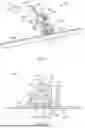
FIGS. 1-3 illustrate a vibrating concrete screed 100 that is used to smooth and level concrete. The vibrating concrete screed 100 includes a frame 102 having first frame rail 104 and a second frame rail 106. The first frame rail 104 includes a proximal end 107 and a distal end 108 formed with a foot 110. Similarly, the second frame rail 106 includes a proximal end 112 and a distal end 114 formed with a foot 116. A first handlebar 118 extends from the proximal end 107 of the first frame rail 104 and a second handlebar 120 extends from the proximal end 112 of the second frame rail 106. The first handlebar 118 includes a trigger assembly 122 having a trigger 124 that is used to control the operation of the vibrating concrete screed 100. The second handlebar 120 includes a kick-stand 126 that can be rotated about a bracket 128 between a stowed position, in which the kick-stand 126 is in a position to not interfere with movement of the vibrating concrete screed and a deployed position, in which the kick-stand 126 supports the vibrating concrete screed 100 in a generally upright position.
A main housing 130 is disposed on the frame 102 and extends between the proximal end 107 of the first frame rail 104 and the proximal end 112 of the second frame rail 106. As shown, the main housing 130 extends above the proximal ends 107, 112 of the frame rails 104, 106. The main housing 130 includes a battery receptacle 132 that is configured to receive a removable battery pack 134. In one example, the battery pack 134 includes one or more cell strings and each cell string includes a number of battery cells (e.g., 10) connected in series to provide a desired discharge output (e.g., nominal voltage [e.g., 20 V, 40 V, 60 V, 80 V, 130 V] and current capacity). The battery cells of the battery pack 134 are any rechargeable battery cell chemistry type, such as, for example, lithium (Li), lithium-ion (Li-ion), other lithium-based chemistry, nickel-cadmium (NiCd), nickel-metal hydride (NiMH), etc. As shown in FIG. 3, an electronic controller 136, e.g., a printed circuit board, is disposed within the main housing 130 and is electrically connected to the trigger 124, the battery receptacle 132 and the battery pack 134 when it is engaged with the battery receptacle 132. The controller 136 includes the control electronics for controlling the operation of the vibrating concrete screed 100.
The vibrating concrete screed 100 also includes a motor housing 140 below the main housing 130 between the first frame rail 104 and the second frame rail 106. The motor housing 140 includes a generally cylindrical sidewall 142 and an upper cap 144. A motor 146 is disposed within the motor housing 140. As best shown in FIG. 3, the motor 146 includes a stator 148. A rotor is disposed within the stator 148 and drives a motor output shaft 150. The motor housing 140 is isolated from the main housing 130 in order to minimize vibration transmission to the main housing 130. The upper cap 144 serves as a raceway for wires connected between the electronic controller 136 and the motor 146.
In the illustrated embodiment, the motor 146 is a brushless directed current (BLDC) electric motor. In other embodiments of the concrete trowel 10, the motor 48 can be configured as a brushed motor, or any other type of electric motor known to someone having ordinary skill in the art. In still other embodiments, the motor 146 may be a combustion engine and in such a case, in lieu of a battery pack 134, the vibrating concrete screed 100 may include a fuel cell and a fuel injection system, or carburetion system, in fluid communication with the motor 146.
A first protective bar 152 extends from the frame 102 between the first frame rail 104 and the second frame rail 106 around and over the main housing 130 to protect the main housing 130 from impacts and to act as a first carry handle. A second protective bar 154 extends from the frame 102 between the first frame rail 104 and the second frame rail 106 around the motor housing 140 to protect the motor housing 140 from impacts and to act as a second carry handle.
The vibrating concrete screed 100 further includes an excitor assembly 160 disposed beneath the motor housing 140 and the bottom of the frame 102, i.e., below the foot 110 of the first frame rail 104 and the foot 116 of the second frame rail 106. The excitor assembly 160 includes an exciter assembly housing 162 having a generally cylindrical central housing portion 164 that is coupled to the bottom of the motor housing 140 in which an imbalanced mass (not shown) is located to create vibration in response to rotation thereof. The excitor assembly 160 further includes a first wing 166 extending from the central housing portion 164 in a first direction and a second wing 168 extending from the central housing portion 164 in a direction opposite the first wing 166. As shown, the first wing 166 and the second wing 168 extend along a first axis 170 that is perpendicular to a second axis 172 that that extends through the motor output shaft 150.
The first wing 166 is connected to the foot 110 of the first frame rail 104 via a first pair of fasteners 174 and a first pair of dampers 176 through which the fasteners 174 extend. The second wing 168 is connected to the foot 116 of the second frame rail 104 via a second pair of fasteners 178 and a second pair of dampers 180 through which the fasteners 178 extends. In an example, the dampers 176, 180 are elastomeric bushings or spring-damper units that are installed to attenuate vibration transmitted to the operator, the controller 136 within the main housing 130, and the battery pack 134.
The excitor assembly 160 further includes a first clamp assembly 182 extending in a downward direction from the first wing 166 and a second clamp assembly 184 extending in a downward direction from the second wing 168. In the example shown, the first clamp assembly 182 and the second clamp assembly 184 are edge clamps configured to engage the upper portion of a screed bar 200, described below, and each clamp assembly 182, 184 includes a groove spaced part from an edge clamp. In another example, the first clamp assembly 182 and the second clamp assembly 184 may be configured as quick-release mechanisms including, for example, over-center cam latches.
As shown in FIG. 4, the screed bar 200 is generally shaped like a right trapezoid (in cross-section) with a first interior triangular chamber 202 and a second interior triangular chamber 204. The screed bar 200 includes an upper plate 210, a lower plate 212, a rear plate 214 extending perpendicularly from the lower plate 212 toward the upper plate 210, and forward plate 216 extending from the lower plate 212 toward the upper plate 210. The screed bar 200 further includes a rearward protrusion 220 formed at the interface of the upper plate 210 and the rear plate 214 and a forward protrusion 222 formed at the interface of the upper plate 210 and the forward plate 216. The protrusions 220, 222 are configured to be captured and held tightly in the first clamp assembly 182 and the second clamp assembly 184 on the excitor assembly 160, as depicted in FIG. 3. Specifically, the rearward protrusion 220 fits into a similarly shaped groove on the excitor assembly 160 and the forward protrusion 222 is engaged with, and held in place by, the first clamp assembly 182 and second clamp assembly 184.
FIG. 5 illustrates another example of a screed bar 500 that has a generally L-shaped body 502 (in cross-section). The L-shaped screed body 502 includes a horizontal plate 504 and a vertical plate 506 extending therefrom. The L-shaped screed bar 500 cannot be attached directly to the excitor assembly 160 of the vibrating concrete screed 100 because the L-shaped screed bar 500 cannot be captured in the first clamp assembly 182 and the second clamp assembly 184. As such, an adapter is required to mount the L-shaped screed bar 500 to the excitor assembly 160.
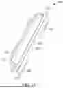
FIGS. 6-13 illustrate a screed bar adapter 600 that is used to connect the L-shaped screed bar 500 to the excitor assembly 160 of the vibrating concrete screed 100. The screed bar adapter 600 includes a body 602 having a central plate 604. A first upper wall 606 extends from the central plate 604 in an upper direction and slightly rearward to establish a rearward protrusion 608. A second upper wall 610 extends from the central plate 604 on the opposite side as the first upper wall 606 in an upper direction and slightly forward to establish a forward protrusion 612. A plurality of perpendicular braces 614 extend between the first upper wall 606 and the second upper wall 610. Moreover, a plurality of angled braces 616 extend between the first upper wall 606 and the second upper wall 610 between adjacent pairs of perpendicular braces 614. As best shown in FIG. 6 and FIG. 8, the angled braces 616 form a saw tooth pattern along the top of central plate 604 of the body 602 of the screed bar adapter 600 between the first upper wall 606 and the second upper wall 610.
As best illustrated in FIGS. 6, 7, 12, and 13, a first lower wall 620 extends in a generally downward direction from the central plate 604. A second lower wall 622 also extends in a generally downward direction from the central plate 604 and is spaced from the first lower wall 620 such that a slot 624 is formed between the first lower wall 620 and the second lower wall 622. As shown, each of the first lower wall 620 and the second lower wall 622 is positioned between the rearward protrusion 608 and the forward protrusion 612. The first lower wall 620 is positioned between the rearward protrusion 608 and the second lower wall 622. The second lower wall 622 is positioned between the first lower wall 620 and the forward protrusion 612. Both of the first and second lower walls 620, 622 are positioned closer to the forward protrusion 612 than the rearward protrusion 608. Accordingly, the slot 624 is also positioned closer to the forward protrusion 612 than the rearward protrusion 608. A plurality of gussets 626 (FIG. 7) extend between the first lower wall 620 and the central plate 604. Moreover, the first lower wall 620 is formed with a plurality of threaded holes 628 and the second lower wall 622 is also formed with a plurality of threaded holes 630. The screed bar adapter 600 includes a plurality of threaded fasteners 632, each of which is threaded with a pair of aligned holes 628, 630 formed in the lower walls 620, 622. The walls 620, 622 and threaded fasteners 632 act as a clamp assembly.
As shown in FIG. 14, the screed bar adapter 600 engages the excitor assembly 160 on the vibrating concrete screed 100. Specifically, the protrusions 608, 612 on the body 602 of the screed bar adapter 600 are configured to be captured and held tightly in the first clamp assembly 182 and the second clamp assembly 184 on the excitor assembly 160. Specifically, the rearward protrusion 608 fits into a similarly shaped groove on the excitor assembly 160 and the forward protrusion 612 is engaged with, and held in place by, the first clamp assembly 182 and second clamp assembly 184. Moreover, the vertical plate 506 of the body 502 of the L-shaped screed bar 500 is installed within the slot 624 of the screed bar adapter 600 between the first lower wall 620 and the second lower wall 622. The fasteners 632 extend through holes formed in the vertical plate 506 of the L-shaped screed bar 500 to secure the L-shaped screed bar 500 to the adapter 600. In other embodiments of the adapter 600, the fasteners 632 may be tightened against a face of vertical plate 506 of the L-shaped screed to apply a clamping force to the vertical plate 506. Accordingly, the screed bar adapter 600 allows the L-shaped screed bar 500 to be attached to the excitor assembly 160.
FIGS. 15-19 illustrate another screed bar adapter 700 that is used to connect the L-shaped screed bar 500 to the excitor assembly 160 of the vibrating concrete screed 100. The screed bar adapter 700 is similar to the screed bar adapter 600 of FIGS. 6-14 and therefore like structure will be identified with like reference numerals plus one hundred (“100”). As will be discussed herein, the main difference between the screed bar adapter 600 of FIGS. 6-14 and the screed bar adapter 700 of FIGS. 15-19 is that the second lower wall 622 and the slot 624 are omitted. Additionally, the braces 614, 616 and the gussets 626 of the screed bar adapter 600 of FIGS. 6-14 are omitted, as well. In other or alternative embodiments, the screed bar adapter 700 may also include braces 614, 616 and the gussets 626 of FIGS. 6-14, as discussed above.
The screed bar adapter 700 includes a body 702 having a central plate 704. A first upper wall 706 extends from the central plate 704 in an upper direction and slightly rearward to establish a rearward protrusion 708. A second upper wall 710 extends from the central plate 704 on the opposite side as the first upper wall 706 in an upper direction and slightly forward to establish a forward protrusion 712.
Further with respect to FIGS. 15-17, a lower wall 720 extends in a generally downward direction from the central plate 704. Moreover, the lower wall 720 is formed with a plurality of through-holes 740. The screed bar adapter 700 includes a plurality of threaded fasteners 732 (FIGS. 18 and 19), which may be bolts, for example. The threaded fasteners 732 each include a head 742 and shaft 744, at least a portion of which is threaded. Each of the shafts 744 is configured to threadably receive a nut 746. As shown, the lower wall 720 is positioned between the rearward protrusion 708 and the forward protrusion 712, and closer to the rearward protrusion 708 than the forward protrusion 712.
As shown in FIGS. 18-19, the screed bar adapter 700 engages the excitor assembly 160 on the vibrating concrete screed 100. Specifically, the protrusions 708, 712 on the body 702 of the screed bar adapter 700 are configured to be captured and held tightly in the first clamp assembly 182 and the second clamp assembly 184 on the excitor assembly 160. Specifically, the rearward protrusion 708 fits into a similarly shaped groove on the excitor assembly 160 and the forward protrusion 712 is engaged with, and held in place by, the first clamp assembly 182 and second clamp assembly 184. Moreover, the vertical plate 506 of the body 502 of the L-shaped screed bar 500 is installed rearwardly of the lower wall 720. As shown, the L-shaped screed bar 500 includes through-holes 750, each of which is configured to align with one of the through-holes 740 of screed bar adapter 700. The threaded fasteners 732 and the nuts 746 couple (e.g., clamp) the L-shaped screed bar 500 to the screed bar adapter 700. Specifically, each of the threaded fasteners 732 is received within the aligned through-holes 740, 750 formed in the lower wall 720 and the vertical plate 506. The head 742 of each of the threaded fasteners 732 is positioned on a front side of the lower wall 720 and the shaft 744 is positioned on a rear side of the vertical plate 506. One of the nuts 746 is threadably coupled to each of the shafts 744 to couple (e.g., clamp) the L-shaped screed bar 500 to the scree bar adapter 700. The threaded fasteners 732 and the nuts 746 therefore act as a clamp assembly to couple the L-shaped screed bar 500 to the screed bar adapter 700. Accordingly, the screed bar adapter 700 allows the L-shaped screed bar 500 to be attached to the excitor assembly 160.
In another embodiment (not shown), the lower wall 720 may include threaded holes, like the embodiment of FIGS. 6-14. In such case, the threaded fasteners 732 may be inserted from the rear side of the L-shaped screed bar 500. The shaft 744 may thus be threadably coupled to the threaded holes to couple the L-shaped screed bar 500 to the screed bar adapter 700. Specifically, the shaft 744 may extend through the through-hole 750 of the vertical plate 506 and be threaded into the respective threaded hole, and the head 742 may be positioned against the rear side of the vertical plate 506. The threaded fasteners 732 may therefore couple the L-shaped screed bar 500 to the screed bar adapter 700.
Although the disclosure has been described in detail with reference to certain preferred embodiments, variations and modifications exist within the scope and spirit of one or more independent aspects of the disclosure as described.
Claims
1. A vibrating concrete screed comprising:
a frame;
a motor coupled to the frame;
an excitor assembly driven by the motor and including a first clamp assembly for coupling a first screed bar having a first configuration;
a screed bar adapter configured to be coupled to the excitor assembly by the first clamp assembly, the screed bar adapter having a second clamp assembly; and
a second screed bar having a second configuration configured to be received by the second clamp assembly on the screed bar adapter.
2. The vibrating concrete screed of claim 1, wherein the screed bar adapter comprises:
a central plate;
a first upper wall extending from the central plate in a first direction and forming a rearward protrusion; and
a second upper wall extending from the central plate in the first direction and forming a forward protrusion.
3. The vibrating concrete screed of claim 2, wherein the rearward protrusion and the forward protrusion are captured in the first clamp assembly on the excitor assembly.
4. The vibrating concrete screed of claim 3, wherein the rearward protrusion is configured to be positioned in a similarly shaped groove of the excitor assembly and the forward protrusion is engaged with, and held in place by, the first clamp assembly.
5. The vibrating concrete screed of claim 3, wherein the screed bar adapter further comprises a lower wall extending from the central plate in a second direction opposite the first direction, and wherein the lower wall includes a through-hole through which a fastener extends to clamp the second screed bar to the lower wall.
6. The vibrating concrete screed of claim 5, wherein the second screed bar includes a horizontal plate and a vertical plate extending from the horizontal plate, wherein the vertical plate includes a through-hole that aligns with the through-hole in the lower wall, and wherein the fastener extends through the through-hole of the lower wall and the through-hole of the vertical plate to clamp the second screed bar to the lower wall.
7.-9. (canceled)
10. A vibrating concrete screed comprising:
a frame;
a motor coupled to the frame;
an excitor assembly driven by the motor and configured to support an upper portion of a first screed bar having a first shape; and
a screed bar adapter having an upper portion coupled to the excitor assembly and configured to support a second screed bar having a second shape different from the first shape of the first screed bar, the upper portion of the first screed bar and the upper portion of the screed bar adapter having a similar shape.
11. The vibrating concrete screed of claim 10, wherein the excitor assembly includes a first clamp assembly, and wherein the upper portion of the first screed bar is engageable with the first clamp assembly.
12. The vibrating concrete screed of claim 11, wherein the upper portion of the screed bar adapter is engageable with the first clamp assembly.
13. The vibrating concrete screed of claim 12, wherein the first screed bar is interchangeable with the screed bar adapter.
14. The vibrating concrete screed of claim 12, wherein each of the upper portion of the first screed bar and the upper portion of the screed bar adapter includes a rearward protrusion configured to be positioned in a similarly shaped groove of the excitor assembly and a forward protrusion configured to be engaged with, and held in place by, the first clamp assembly.
15. The vibrating concrete screed of claim 11, wherein the screed bar adapter comprises:
a central plate;
a first upper wall extending from the central plate in a first direction and forming a rearward protrusion; and
a second upper wall extending from the central plate in the first direction and forming a forward protrusion.
16. The vibrating concrete screed of claim 15, wherein the rearward protrusion and the forward protrusion are captured in the first clamp assembly on the excitor assembly.
17. The vibrating concrete screed of claim 16, wherein the screed bar adapter further comprises:
a lower wall extending from the central plate in a second direction opposite the first direction, the lower wall configured to be clamped to the second screed bar via a fastener.
18. The vibrating concrete screed of claim 17, wherein the lower wall includes a through-hole, wherein the second screed bar includes a horizontal plate and a vertical plate extending from the horizontal plate, wherein the vertical plate includes a through-hole that aligns with the through-hole in the lower wall, and wherein the fastener extends through the through-hole of the lower wall and the through-hole of the vertical plate to clamp the second screed bar to the lower wall.
19.-21. (canceled)
22. A screed bar adapter for use with a vibrating concrete screed, the screed bar adapter comprising:
a central plate;
a first upper wall extending from the central plate in a first direction and forming a rearward protrusion; and
a second upper wall extending from the central plate in the first direction and forming a forward protrusion, wherein the rearward protrusion and the forward protrusion are removably engaged with an excitor assembly on the vibrating concrete screed.
23. The screed bar adapter of claim 22, wherein the screed bar adapter further comprises a lower wall extending from the central plate in a second direction opposite the first direction, the lower wall includes a through-hole through which a fastener extends to clamp a screed bar to the lower wall.
24. The screed bar adapter of claim 23, wherein lower wall is positioned between the rearward protrusion and the forward protrusion, and wherein the lower wall is positioned closer to the rearward protrusion than the forward protrusion.
25. The screed bar adapter of claim 23, wherein the screed bar includes a horizontal plate and a vertical plate extending from the horizontal plate, wherein the vertical plate includes a through-hole that aligns with the through-hole in the lower wall, and wherein the fastener extends through the through-hole of the lower wall and the through-hole of the vertical plate to clamp the screed bar to the lower wall.
26.-28. (canceled)
Images & Drawings included:


Sources:
- United States Patent and Trademark Office - verify current appl. status at the USPTO↗
Recent applications in this class:
- » 20240410186 2024-12-12
VIBRATING SCREED - » 20240337115 2024-10-10
ATTACHMENT FOR SCREEDING CONCRETE - » 20240318439 2024-09-26
VIBRATING SCREED - » 20240084606 2024-03-14
Apparatus and system for surface processing of plastically deformable masses - » 20230366218 2023-11-16
CONCRETE SCREED DEVICE WITH OSCILLATING SCREED BAR - » 20230366217 2023-11-16
CONCRETE SCREED DEVICE WITH OSCILLATING SCREED BAR - » 20230258005 2023-08-17
CONCRETE SCREEDING MACHINE WITH WALL EDGE SCREEDING FEATURE - » 20230235579 2023-07-27
HAND-HELD VIBRATING CEMENT TROWEL - » 20230228106 2023-07-20
BATTERY PACK-POWERED SCREED - » 20230057404 2023-02-23
FLOAT, FLOAT ASSEMBLIES, FLOAT ADAPTERS AND INTERFACES, VIBRATION APPARATUS, AND GROOVERS AND METHODS