Dynamic Dry Room (DDR) Hydraulic Locking System
US20250290341A1
2025-09-18
19/081,819
2025-03-17
Smart Summary: A dynamic dry-room hydraulic locking system is designed to create a secure and adjustable space. It features a movable wall framework made up of support rings that have points where locks can connect. There are also movable wall segments that can lock into these points to hold them in place. This setup allows the walls to be easily adjusted and secured as needed. Overall, it provides flexibility while ensuring safety and stability in the dry room. 🚀 TL;DR
Abstract:
A dynamic dry-room (DDR) hydraulic locking system is disclosed. In some examples, the DDR hydraulic locking system includes a movable wall framework including a plurality of support ring structures, wherein each of the support ring structures includes a plurality of lock engagement points. The DDR hydraulic locking system further includes at least one movable wall structure segment including a plurality of wall movement locks that interface with a plurality of lock engagement points of the movable wall framework, wherein the at least one movable wall structure segment is configured to be secured at a fixed position at one of the support ring structures via a plurality of wall movement locks respectively positioned at the plurality of lock engagement points.
Applicant:
Interested in similar patents?
Get notified when new applications in this technology area are published.
Classification:
E04H5/02 » CPC main
Buildings or groups of buildings for industrial or agricultural purposes Buildings or groups of buildings for industrial purposes, e.g. for power-plants, factories
Description
CROSS-REFERENCE TO RELATED APPLICATIONS
This application claims priority to U.S. Provisional Patent Application No. 63/565,570, filed on Mar. 15, 2024, the disclosure and content of which is incorporated by reference herein in its entirety.
TECHNICAL FIELD
The present disclosure relates to dry room systems, and more particularly, to a dynamic dry room hydraulic locking system conducive for battery manufacturing.
BACKGROUND
At present, dry rooms utilized for battery manufacturing consist of controlled environments with low humidity levels (e.g., typically below 1% relative humidity) that are designed to prevent moisture from affecting the performance and safety of batteries during testing. These dry rooms are crucial for testing lithium-ion batteries and other sensitive battery types, as moisture can lead to chemical reactions, degradation, and/or short-circuiting. Most dry rooms are equipped with specialized air filtration and dehumidification systems to maintain the optimal conditions required for accurate and safe testing of battery performance, stability, and durability. However, conventional dry rooms are typically built as static, non-modifiable structures, requiring significant capital investment. In many cases, these dry rooms are constructed larger than the immediate operational needs to accommodate potential future expansion. However, this approach often results in unnecessary expenses related to construction, energy consumption, and climate control (e.g., air conditioning and humidity regulation) for an oversized space that may not be fully utilized.
SUMMARY
A dynamic dry-room (DDR) hydraulic locking system is disclosed. In some embodiments, the DDR hydraulic locking system includes a movable wall framework including a plurality of support ring structures, wherein each of the support ring structures includes a plurality of lock engagement points. The DDR hydraulic locking system further includes at least one movable wall structure segment including a plurality of wall movement locks that interface with a plurality of lock engagement points of the movable wall framework, wherein the at least one movable wall structure segment is configured to be secured at a fixed position at one of the support ring structures via a plurality of wall movement locks respectively positioned at the plurality of lock engagement points.
In some embodiments of the disclosed subject matter, the at least one movable wall structure segment is equipped with one or more sensors configured to monitor pressure levels and automatically engage locking pins of the wall movement locks into the engagement points, such that the position of the at least one movable wall structure segment is maintained despite fluctuations in surrounding air pressure.
In some embodiments of the disclosed subject matter, the DDR hydraulic locking system further comprises a manual override feature enabling the disengagement of the wall movement locks to allow for emergency repositioning or evacuation procedures.
In some embodiments of the disclosed subject matter, the DDR hydraulic locking system further comprises a plurality of wall movement drive units, each of which includes a motor-driven assembly connected to a ball screw or linear actuator mechanism,
In some embodiments of the disclosed subject matter, the DDR hydraulic locking system further comprises an artificial intelligence (AI) control system configured to regulate the speed and position of the at least one movable wall structure segment.
In some embodiments of the disclosed subject matter, the AI control system is capable of receiving input from environmental sensors and executing movement commands based on predetermined environmental conditions or safety protocols.
In some embodiments of the disclosed subject matter, the DDR hydraulic locking system further comprises a threaded wall movement groove that defines a path for positioning the at least one movable wall structure segment.
In some embodiments of the disclosed subject matter, each of the plurality of support ring structures comprises: a durable frame configured for encircling the perimeter of one of the movable wall structure segments; alignment features to maintain one of the movable wall structure segment's trajectory and seal integrity; and adaptable mounting points for integration with structural elements of the movable wall framework.
In some embodiments of the disclosed subject matter, each of the plurality of support ring structures further includes adjustable sealing elements that interface with the edges of one of the movable wall structure segments to enhance environmental containment when said one of the movable wall structure segments is in a fixed position.
In some embodiments of the disclosed subject matter, each of the movable wall structure segments is constructed from materials that provide fire resistance, sound attenuation, and thermal insulation.
In some embodiments of the disclosed subject matter, each of the movable wall structure segments includes integrated sealing mechanisms to maintain environmental control when in a fixed position, a plurality of wall movement drive units, and the plurality of wall movement locks.
In some embodiments of the disclosed subject matter, each of the movable wall structure segments includes embedded data transmission pathways for integrating sensors, communication devices, or environmental monitoring equipment.
In some embodiments of the disclosed subject matter, each of the movable wall structure segments is constructed from one or more fire-retardant materials including aluminum, phosphate, borates, halogenated compounds, fabrics, glass, special paint, and/or plastics.
BRIEF DESCRIPTION OF THE DRAWINGS
Aspects and embodiments are now described, by way of example, with reference to the accompanying drawings, in which:
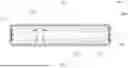
FIG. 1 is an isometric view of an example DDR system in accordance with embodiments of the disclosed subject matter;
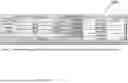
FIG. 2 is a front view of an example movable wall structure segment with a pass through air lock in accordance with embodiments of the disclosed subject matter;
FIG. 3 is a front view of an example movable wall structure segment without a pass through air lock in accordance with embodiments of the disclosed subject matter;
FIG. 4 is an isometric view of a fire retardant wall structure segment in accordance with embodiments of the disclosed subject matter;
FIG. 5 is a front expanded view of a portion of a movable wall structure segment in accordance with embodiments of the disclosed subject matter;
FIG. 6 is an isometric view of an example sealing system for a movable wall structure segment in accordance with embodiments of the disclosed subject matter;
FIG. 7 is an internal view of an example movable wall structure segment in accordance with embodiments of the disclosed subject matter;
FIG. 8 is an isometric view of an example humidity control vent in accordance with embodiments of the disclosed subject matter;
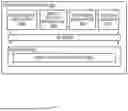
FIG. 9 is a block diagram of a DDR system server in accordance with embodiments of the disclosed subject matter; and
FIG. 10 illustrates a table comparing total energy utilization costs between a standard dry room and a dynamic dry room in accordance with embodiments of the disclosed subject matter.
DETAILED DESCRIPTION
Inventive concepts will now be described more fully hereinafter with reference to the accompanying drawings, in which examples of embodiments of inventive concepts are shown. Inventive concepts may, however, be embodied in many different forms and should not be construed as limited to the embodiments set forth herein. Rather, these embodiments are provided so that this disclosure will be thorough and complete, and will fully convey the scope of present inventive concepts to those skilled in the art. It should also be noted that these embodiments are not mutually exclusive. Components from one embodiment may be tacitly assumed to be present/used in another embodiment.
The following description presents various embodiments of the disclosed subject matter. These embodiments are presented as teaching examples and are not to be construed as limiting the scope of the disclosed subject matter. For example, certain details of the described embodiments may be modified, omitted, or expanded upon without departing from the scope of the described subject matter.
In the present disclosure, the disclosed Dynamic Dry Room (DDR) hydraulic locking system (hereinafter referred to as ‘DDR system’) is designed and/or configured to operate in limited spaces based on user demand, which can significantly reduce energy consumption before attaining its maximum spatial capacity. The multi-sectional space in the DDR system allows for multiple humidity-controlled zones that are adapted for various moisture-sensitive materials used in battery material manufacturing and storage. In some embodiments, the DDR system can be configured to automatically adjust dry-air load and maintain optimal conditions by factoring in occupancy and breathing rates, thereby ensuring energy-efficient operation. Moreover, the DDR system may utilize a fire-retardant door that provides a safe zone for operation evacuation, which reduces the possible damage area(s) from fire accidents. Overall, the disclosed DDR system is designed to efficiently manage global market fluctuations (e.g., unpredictable and varying demands of the battery manufacturing market) and facilitate a cost-effective manufacturing process. Notably, the sectional design of the disclosed DDR system enables the handling of various moisture-sensitive materials within the same system, thus eliminating the need for additional infrastructure and reducing immediate capital expenditure. Additionally, by optimizing energy usage, the DDR system supports decarbonization efforts and minimizes environmental impact, making it a cost-effective and sustainable solution for the global market.
An isometric view of an example DDR system framework 100 is illustrated in FIG. 1. For example, DDR system framework 100 (i.e., a movable wall framework) represents a “base” dry room that is structured around a series of aligned support rings 120 (i.e., support ring structures), which can be utilized for constructing a segmented, multi-zone dry environment. The support rings 120, in coordination with a threaded wall movement groove (e.g., a track and guidance system), provide a stable ‘movable wall structure segment’ framework configured for the insertion and linear movement of one or more movable wall structure segments 110. This framework 100 and setup allow for the creation and modification of distinct zones (e.g., segmented and separate rooms), each of which can be tailored to specific humidity control requirements. For example, FIG. 1 illustrates three separate zones 101-103 (e.g., “zone 1”, “zone 2”, and “zone 3”, respectively) that can be spatially defined by the positioning of the movable wall structure(s) 110 at the support rings 120 positioned along the framework 100. In some embodiments, each support ring structure may include a durable frame configured for encircling the perimeter of the movable wall structure segments, alignment features to maintain the movable wall structure segment's trajectory and seal integrity, and adaptable mounting points for integration with structural elements of the movable wall framework. In some embodiments, each of the support ring structures may include adjustable sealing elements (e.g., gaskets) that interface with the edges of one of the movable wall structure segments to enhance environmental containment when the movable wall structure segment is in a fixed position. Notably, these support ring structures facilitate the secure and precise placement of movable walls, contributing to the partitioned spaces' overall rigidity and environmental isolation.
In some embodiments, the design of DDR system 100 prioritizes modularity and precision, thereby enabling scalable configurations within the DDR system itself. For example, the uniform spacing of the support rings 120 and the integration with the threaded wall movement groove facilitate the straightforward addition and/or repositioning of movable wall structure segments 110, ensuring adaptability to various operational demands while maintaining environmental control integrity. For example, the threaded wall movement groove (not shown) may define a path for positioning the at least one movable wall structure segment.
In some embodiments, zones 101-103 may include defined areas within DDR system framework 100. Each of zones 101-103 can be delineated by one or two movable wall structure segments 110 and can thus be used for separate and specific manufacturing purposes. For example, each of zones 101-103 operates under independent conditions managed by an artificial intelligence (AI) control system (e.g., an AI-based DDR control manager 914 hosted by a DDR system server 900 as shown in FIG. 9). Each zone may require a different moisture level, which can be regulated through pressure control by the AI control system. The AI control system is designed to accommodate and indicate different pressure control settings accordingly. For example, the AI control system is designed to dynamically adjust parameters such as relative humidity levels, accounting for factors like the number of personnel contributing to internal moisture, as well as the required dry air circulation. These adjustments are based on pre-generated advanced predictive models and real-time data obtained from cameras and sensors integrated into the DDR system. In some embodiments, the environmental settings of each zone are autonomously managed by the AI control system, which ensures optimal conditions that are tailored for separate and distinct process requirements. In some embodiments, the AI-integrated control system (e.g., DDR control manager) is facilitated through real-time data analysis, enabling precise control over humidity and temperature levels, which are essential for maintaining process integrity and operational efficiency in specialized manufacturing environment.
In some embodiments, the DDR system framework 100 comprises hydraulic and wall-locking systems that are compatible with the aforementioned support rings 120. Further, the DDR system framework 100 should be designed with multi-room functionality so that different types of moisture-sensitive materials can be handled within multiple humidity infrastructures.
FIG. 2 illustrates a front view of an example movable wall structure segment 200. Notably, movable wall structure segment 200 includes a pass-through air lock 202, which is configured for efficient transitions between controlled environments. In some embodiments, the pass-through air lock 202 includes at least two doors (e.g., pocketing sliding doors) and a compliance-based step(s) 204 positioned adjacent to the movable wall structure segment 200. In some embodiments, movable wall structure segment 20 includes a plurality of variable volume humidity blowers (VVHBs) 206, which can be used to direct ultra-dry air to eliminate particulates from personnel, thereby mitigating cross-contamination risks during inter-zone movement. These VVHBs 206 are described in further detail below.
In some embodiments, the sequence of door operations ensures airtight sealing. In particular, only one door of pass-through air lock 202 can open at a time, thus maintaining environmental integrity by preventing simultaneous open states (i.e., multiple doors opened simultaneously) which would compromise the environment conditions of the dry room and/or dry room zone. The sequential door operation, which is critical for maintaining controlled conditions, combines advanced contamination control with safety protocols that are essential for high-standard cleanroom functionalities in sensitive and regulated industries. For example, the air lock system and/or pass-through air lock 202 is configured for safety and regulatory adherence, and may incorporate OSHA-compliant steps and handrails. In some embodiments, the doors of pass-through air lock 202 can operate on a pneumatic system designed for emergency situations, thus allowing automatic opening to ensure an expedited evacuation route.
FIG. 2 further depicts an example camera system that includes one or more camera units 208. For example, movable wall structure segment 200 may be equipped with a six-camera system that can be used for monitoring activities on both sides of movable wall structure segment 200. Notably, camera unit(s) 208 may be configured to capture image and/or video data of zone occupants and processed materials in one or more DDR system zones. In some embodiments, the captured image and/or video data is transmitted to the AI control system, which correlates this data with humidity control metrics to refine real-time humidity level predictions and optimize moisture removal through the control of VVHBs. The integrated camera system enhances energy efficiency and environmental control by enabling dynamic adjustments based on the observed state of personnel and materials within the DDR system zones. Additionally, the camera surveillance aids in creating comprehensive batch histories, which are needed for conducting quality control and process validation(s). In some embodiments, the AI control system's analytical capabilities extend to tracing contamination sources and identifying quality lapses. By leveraging the image/video data captured by camera unit(s) 208 for targeted problem-solving and regulatory compliance, the AI control system can ensure a controlled, well-documented manufacturing environment.
In some embodiments, movable wall structure segment 200 may include one or more integrated sealing mechanisms, such as an integrated dry-room gasket 216. The integrated dry-room gasket 216 is also depicted in FIGS. 3, 5, and 6 of the present disclosure. In some embodiments, the integrated dry-room gasket 216 comprises a hydraulic expandable design that utilizes a plurality of gasket tubes (e.g., six gasket tubes, collectively represented by tubes 216 and 216A shown in FIG. 6) along and in between the movable wall structure segments and the support ring to ensure an airtight and environmental seal between DDR zones. For example, by utilizing non-reactive hydraulic oil (e.g., mineral oil), the DDR system mitigates contamination risks from leaks or failures. The integrated dry-room gasket 216 maintains zone integrity, thereby enabling the prompt detection of air and/or hydraulic leaks. More specifically, the movable wall structure segment, with the integrated dry-room gasket, functions to maintain positive air pressure between different rooms while also incorporating an independent air and hydraulic leak detection system. This design ensures zone integrity and enhances the efficiency of environmental control within the DDR system.
In some embodiments, integrated dry-room gasket(s) 216 may be constructed from a flexible, rubber-like polymer that allow the plurality of gasket tubes (of dry-room gasket 216) to expand when pressurized. After the gasket tubes are expanded in this manner, the dry-room gasket 216 seals the gaps between the movable wall structure segment and support structures (e.g., the support rings of the DDR framework). The expanded dry-room gasket 216 forms a continuous, airtight barrier that prevents cross-zone contamination and maintains environmental control. The material and hydraulic design of dry-room gasket 216 provide durability and adaptability, which ensure effective sealing functionality over repeated operations. Similarly, the gasket(s) 216 may be deflated by the AI control system to enable the repositioning of the movable wall structure segment at another location along the system framework. In some embodiments, a pressure modulation mechanism allows for engaging or disengaging a movable wall structure segment from a fixed position based on differential hydraulic pressure.
As indicated above, movable wall structure segment 200 shown in FIG. 2 includes a plurality of variable volume humidity blowers (VVHBs) 206. The VVHBs 206 are also depicted in FIGS. 3, 5, and 7 of the present disclosure. In some embodiments, VVHBs 206 are sophisticated components in the disclosed DDR system that are designed to maintain optimal humidity levels within a defined space (e.g., DDR zone) through the precise regulation of air flow. The disclosed subject matter may leverage an AI control system to control the VVHBs 206 in order to allow for the dynamic adjustment of air volume supplied to and extracted from the environments of the DDR zones (e.g., zones 101-103 in FIG. 1). This AI-driven control system may facilitate the delivery of dry air into the duct system on demand, while simultaneously evacuating humidified air. Such an operation by the AI control system maintains a balanced and desired atmospheric condition in the zone(s). One particular feature of VVHBs 206 pertains to their ability to generate positive air pressure in distinct DDR zones, which is a critical factor in preventing unwanted infiltration of external humid air and ensuring the uniformity of the conditioned air within a zone's space. Furthermore, VVHBs 206 are intricately designed to control not only the air velocity but also the air pressure within the environment. This control allows the system's operation highly programmable and adaptable to varying conditions. By regulating the speed of their blowers/fans, the VVHBs 206 may adjust the duration or resistance time the air spends during the dehumidification process, which directly influences the relative humidity levels within each zone. This functionality of the VVHBs 206 enables the creation of distinct climate zones (e.g., zones 101-103 shown in FIG. 1) within a single environment that range from dry to less dry, according to specific requirements. When used in conjunction with humidity control vents 210, VVHBs 206 can efficiently manage large volumes of air transfer between DDR zones, which establish a cascading effect of relative humidity levels. In some embodiments, each VVHB 206 plays an important role in significantly reducing energy consumption by enabling the full reuse of dry air from one room to another. This optimization enhances efficiency and minimizes waste, making the DDR system more sustainable and cost-effective. Notably, this systematic approach and use of the VVHBs not only ensures the maintenance of optimal environmental conditions but also enhances energy efficiency by tailoring the humidity and temperature settings to the precise needs of each zone.
As indicated above, movable wall structure segment 200 shown in FIG. 2 includes a plurality of humidity control vents (HCVs) 210. The HCVs 210 are also depicted in FIGS. 3, 5, and 7 of the present disclosure. In some embodiments, HCVs 210 are configured to facilitate climate control by precisely delivering and removing quantities of air when paired with VVHBs 206. Each HCV 210 includes an independent blower (e.g., mini VVHB blower 802 in FIG. 8) and a moisture sensor (e.g., humidity sensor 804 in FIG. 8), which enables real-time humidity monitoring in a given zone. By adjusting the airflow speed individually, the HCVs 210 adjust the air circulation to match specific moisture conditions, thereby enhancing the DDR system's response to environmental changes. The HCVs 210 are linked to the VVHBs 206 through ductwork 750 (see FIG. 7) within the movable wall structure segment, thereby allowing adaptable air management according to spatial humidity requirements. In some embodiments, the movable wall structure segment may be equipped with embedded data transmission pathways for integrating sensors, communication devices, or environmental monitoring equipment.
FIG. 3 is a front view of an example movable wall structure segment 300 without a pass through air lock in accordance with embodiments of the disclosed subject matter. Notably, movable wall structure segment 300 may include the same VVHBs 206, HCVs 210, wall movement drive unit 212, support ring structure 214 (similar to aforementioned support ring structure 120), camera 208, and dry-room gasket 216 that is included in movable wall structure segment 200 depicted in FIG. 2. While movable wall structure segment 300 is a wall structure segment that is devoid of any pass through air lock, segment 300 may operate similarly to segment 200 in every other manner.
FIG. 4 is an isometric view of a fire retardant wall structure segment 400. In some embodiments, fire retardant wall structure segment 400 is similar to wall structure segment 300 (as depicted in FIG. 3) that is further engineered with integrated safety features for enhanced fire response via the utilization of fire-retardant materials and automated mechanisms. In emergency scenarios involving fire detection and/or power failure, the DDR system may activate automatic wall closures and may directly interface with the facility's fire alarm systems for immediate response, thereby isolating the fire-affected zone to prevent the spreading of fire and/or smoke. Additionally, a fire retardant wall structure segment's pneumatic doors (e.g., if segment is equipped with a pass-through air lock) may are equipped with mechanical release latches that allow manual operation in emergencies. This feature ensures that, in case of fire or power loss, occupants can quickly activate these latches to open the doors, thereby facilitating immediate evacuation through the pass-through air lock. In some embodiments, this manual override feature is designed for reliability and easy access, which ensure safety protocols are maintained even when standard power-dependent systems fail. Notably, the manual override feature can provide occupants a fail-safe mechanism for rapid egress. In some embodiments, fire retardant wall structure segment 400 is designed using fire-retardant materials such as aluminium, phosphate, borates, halogenated compounds, fabrics, glass, special paint, and/or plastics. These example materials are essential for fire safety, as they provide additional time for building occupants to evacuate and can help minimize property damage during a fire. Moreover, the DDR system may feature other enhanced fire containment capabilities, including automatic wall closures to isolate fire incidents. In some embodiments, the movable wall structure segment 400 may be constructed from materials that provide sound attenuation and thermal insulation, in addition to providing fire resistance.
FIG. 4 further includes an expanded view portion designated by circle 401. In particular, circle 401 illustrates a plurality of wall movement locks 404 included in fire retardant wall structure segment 400. Although FIG. 4 specifically depicts fire retardant wall structure segment 400 as including the wall movement locks 404, it is understood that any wall structure segment described or illustrated in the present disclosure may include similar wall movement locks.
Wall movement locks 404 are further detailed in FIGS. 5 and 7. In some embodiments, wall movement locks 404 are configured to utilize hydraulic actuated pistons (e.g., located in the support ring) for securing the movable wall structure segment 110 to the support ring 120 (as shown in FIG. 1), thereby ensuring proper wall alignment and stability. Notably, the use of wall movement locks with the support ring enables the movable wall structure segment(s) to become securely rigid and properly centered. The positioning of the movable wall structure segment(s) is essential for uniform load distribution and consistent gasket compression along both the movable wall structure segment and the surrounding framework (e.g., the support ring). The engagement of the pistons (e.g., functioning as locking pins) in the wall movement locks 404 with the spring-loaded pressure cups of the wall structure segment enables the movable wall structure to effectively counteract positive air pressure and mitigate environmental fluctuation. In some embodiments, the pistons of the wall movement locks 404 may be integrated in the movable wall structure segments. In some embodiments, the movable wall structure segment may be equipped with one or more sensors configured to monitor pressure levels and automatically engage locking pins of the wall movement locks into the engagement points, such that the position of the at least one movable wall structure segment is maintained despite fluctuations in surrounding air pressure.
In addition, the hydraulic locking pistons (of wall movement locks 404) are crucial for ensuring the stability of pass-through air lock systems when integrated. The hydraulic locking pistons provide a robust locking mechanism that maintains the position of the movable wall structure segment against the support ring, which is necessary for air lock functionality and environmental control within the DDR. This allows seamless operation and maintains the integrity of isolated zones. In some embodiments, the movable wall structure element of the DDR system also includes a manual override feature (e.g., a physical handle, graphical user interface (GUI) button, or the like readily accessible to a user or operator) enabling the disengagement of the wall movement locks to allow for emergency repositioning or evacuation procedures.
In some embodiments, the fire retardant wall structure segment 400 shown in FIG. 4 includes a blower gasket 406. Although FIG. 4 specifically depicts fire retardant wall structure segment 400 as including the blower gasket 406, it is understood that any wall structure segment described or illustrated in the present disclosure may include similar blower gaskets. Blower gasket 406 may be positioned on the side of the movable wall structure segment, such that the gasket interfaces with the VVHBs on the support ring. In some embodiments, blower gasket 406 is constructed from an expandable hollow rubber-polymer, which enable the blower gasket to inflate via hydraulic pressure. The inflation of the blower gasket 406 allows it to seal against the vents of the support ring, thereby ensuring an airtight seal and/or connection. The use of blower gaskets in this manner is critical for integrating the movable wall structure segment with the ventilation system in order to allow for controlled air transfer and to maintain environmental conditions in the DDR zone(s). After inflation, the blower gasket 406 facilitates the pressurization of the wall structure segment's ventilation network by the variable volume humidity blowers (as shown in FIG. 8), which manage the air humidity levels via humidity control vents 410. Notably, the delivery of dry air and the removal of moist air can be conducted through the one or more humidity control vents 410 shown in FIG. 4. This process is necessary for maintaining precise humidity levels within the DDR zone(s) and emphasizes the role of blower gasket 406 in optimizing the humidity control efficiency.
In some embodiments, the fire retardant wall structure segment 400 shown in FIG. 4 includes a wall movement drive unit 408 (which is identical to wall movement drive unit 212 in FIGS. 2 and 3). Although FIG. 4 specifically depicts fire retardant wall structure segment 400 as including the wall movement drive unit 408, it is understood that any wall structure segment described or illustrated in the present disclosure may include similar wall movement drive. For example, wall movement drive unit 408 may employ an inverted ball screw mechanism (that interacts with a motor-driven assembly) for its operation and features a threaded slot in each corner of the support ring. In some embodiments, rotating powered shafts of wall movement drive unit 408 engage with these threaded slots, which convert rotational movement into linear motion. Such interaction produced by the wall movement drive 408 compels the movable wall structure segment to move forward or backward along a path of the framework based on shaft rotation direction. In some embodiments, the wall movement drive unit 212 incudes a motor-driven assembly connected to a linear actuator mechanism. The DDR system's design ensures precise movement control, which is also necessary for maintaining environmental seals. Moreover, synchronization of the wall movement drive unit 408 at all four points of the movable wall structure segment (e.g., see the four wall movement drive units 212 in FIG. 3) is essential to enable the wall structure segment to maintain its vertical orientation and ensuring a perpendicular alignment with the DDR room's floor and ceiling. This coordination prevents structural misalignments and preserves the integrity of the dry room's-controlled environment. The efficiency and precision of wall movement drive 408 facilitates the adaptable yet secure positioning of the movable wall structure segment within the DDR system.
FIG. 5 illustrates a front expanded view 500 of a portion of a movable wall structure segment, such as movable wall structure segment 200 (shown in both FIGS. 2 and 7). In particular, expanded view 500 depicts a corner of a movable wall structure segment that includes a support ring structure 214 (similar to support ring structure 120 and belonging to the system framework) interfacing with the gasket 216 of the movable wall structure segment. FIG. 5 also shows the wall movement drive 408 and wall movement locks 404 of the movable wall structure segment.
FIG. 6 illustrates an example sealing system for a movable wall structure segment. In particular, FIG. 6 illustrates the positioning of the plurality of gasket tubes of dry-room gasket 216. In particular, expanded view 601 in FIG. 6 depicts 6 total gasket tubes represented by three whole gasket tubes 216 and a segmented view (i.e., a “cut away” reference) of three gasket tubes 216A. Notably, gasket tubes 216A are embodied as full tubes (i.e., not segmented as depicted in FIG. 6) similar to gasket tubes 216 when in operation. As indicate above, the gasket tubes of dry-room gasket 216 may be inflated and expanded to create an airtight seal between a movable wall structure segment and the DDR's support ring.
FIG. 7 illustrates an internal view of an example movable wall structure segment in accordance with embodiments of the disclosed subject matter. Notably, wall structure segment 200 depicts the internal ductwork 750 that serves to connection the VVHBs 206 to the various HCVs 210 and pass through air lock 202. Expanded view circle 500 illustrates the portion of the movable wall structure segment shown in FIG. 5.
FIG. 8 illustrates an example humidity control vent (HCV) 800 in accordance with embodiments of the disclosed subject matter. Notably, HCV 800 is representative of the HCVs 210 and 410 depicted in FIGS. 2, 3, 4, 5, and 7. In some embodiments, HCV 800 comprises a face plate that protrudes away from the surface of the movable wall structure segment to create a vent opening 810. Each HCV 800 is also equipped with a mini VVHB 802 and a humidity sensor 804, both of which can be controlled by an AI control system.
FIG. 9 is a block diagram of a DDR system server 900 in accordance with embodiments of the disclosed subject matter. In some embodiments, the DDR system utilizes an AI control system (e.g., an AI-driven mechanism) that is executed by the DDR system server 900 and allows for dynamic adjustment of airflows by creating pulsating patterns based on predictive modeling from moisture data collected by the vents. Integration with the aforementioned camera system (e.g., cameras 208) permits the AI control system to construct humidity profiles for individuals, predict moisture impact, and adjust air velocities within the DDR system. The AI control system's processing ensures optimal environmental conditions in the DDR zones by maximizing energy efficiency and maintaining targeted humidity levels. Notably, the AI control system can operate in this manner based on direct feedback and predictive analytics from ongoing environmental and occupancy changes. In some embodiments, the AI control system is configured to regulate the speed and position of the movable wall structure segment(s).
As described herein, the AI control system may be embodied as a software based DDR control manager 914 that is executed by and operated on a DDR system server 900 or other computing device. In some embodiments, the DDR system server 900 includes processing circuitry 902 that is operatively coupled via a bus 904 to an input/output interface 906, a network interface 908, a power source 910, and a memory 912. Other components may be included in other embodiments.
In some embodiments, processing circuitry 902 may include a microprocessor, controller, microcontroller, central processing unit, digital signal processor, application specific integrated circuit, field programmable gate array, any other type of electronic circuitry, or any combination of one or more of the preceding. The processing circuitry 902 may comprise one or more processor cores. In particular embodiments, some or all of the functionality described herein as being provided by system server 900 may be implemented by processing circuitry 902 executing software instructions, either alone or in conjunction with other DDR system server components, such as memory 912.
Memory 912 may store code (which is composed of software instructions and which is sometimes referred to as computer program code or a computer program) and/or data using non-transitory machine-readable (e.g., computer-readable) media, such as machine-readable storage media (e.g., magnetic disks, optical disks, solid state drives, read only memory (ROM), flash memory devices, phase change memory) and machine-readable transmission media (e.g., electrical, optical, radio, acoustical or other form of propagated signals-such as carrier waves, infrared signals). For instance, memory 912 may comprise non-volatile memory containing code to be executed by processing circuitry 902. Where memory 912 is non-volatile, the code and/or data stored therein can persist even when the network device is turned off (when power is removed). In some instances, while DDR system server 900 is turned on that part of the code that is to be executed by the processing circuitry 902 may be copied from non-volatile memory into volatile memory (e.g., dynamic random access memory (DRAM), static random access memory (SRAM)) of DDR system server 900. As shown in FIG. 9, memory 912 may include one or more computer program applications including DDR control manager 914, which may be an AI-based software program.
In some embodiments, the DDR control manager 914 is configured to autonomously maintain optimal humidity levels and airflow conditions in the zones of DDR system (in addition to the functionalities and features previously described above). In some embodiments, DDR control manager 914 (i.e., the AI control system) is configured to receiving input from environmental sensors and executing movement commands based on predetermined environmental conditions or safety protocols. For example, the DDR control manager is responsible for collecting and analyzing data from various sensors, including humidity sensors, gas sensors, oxygen sensors, temperature sensors, and personnel detection systems through camera units located within the dry room. Using this data, the DDR control manager 914 may generate predictive models to optimize environmental conditions and system efficiency in real time. More specifically, the DDR control manager 914 may utilize predictive modeling, real-time data analysis, and intelligent automation to control several mechanical components of the DDR system including VVHBs, camera units, HCVs, and the like. By controlling these DDR system components, the DDR control manager may effectively control the humidity, temperature, air flow, air pressure, and other similar environment conditions that are present in the DDR zones. Moreover, DDR control manager may monitor these zone conditions using a plurality sensor devices (e.g., gas sensors, camera units, etc.) which provide real-time measurement data for moisture data levels, temperature levels, airflows, and the like.
As indicated above, the DDR control manager may also be integrated with and/or communicatively connected to the camera system. Such integration enables the DDR control manager to construct individual humidity profiles, predict moisture impacts, and adjust air velocities accordingly. By correlating visual data with environmental condition metrics (e.g., humidity control metrics), the DDR control manager 914 can further refine its predictive models via machine learning, thereby optimizing moisture removal strategies and ensuring stable environmental conditions even in changing occupancy scenarios.
In some embodiments, an operator may access the DDR system server 900 and/or DDR control manager 914 using a client device, which can include one or more human-machine interfaces or client interfaces (e.g., graphical user interfaces, reporting interfaces, text-based computer interfaces, client-facing web services, web servers that provide pages to web clients, etc.) for controlling, viewing, or otherwise interacting with DDR system server, its subsystems, and/or components. The client device can be a stationary terminal or a mobile device. For example, the client device can be a desktop computer, a computer server with a user interface, a laptop computer, a tablet, a smartphone, a PDA, or any other type of mobile or non-mobile device. In some embodiments, the client device can communicate with DDR system server via input/output interface 906 or network interface 908.
Results
The disclosed DDR technology offers high energy efficiency, wide flexibility, and strong sustainability. It is projected to reduce energy consumption (i.e., energy cost) by 30% over 36 months compared to the standard dry room (hereafter, SDR), as shown in FIG. 10. The disclosed DDR system not only improves energy efficiency but also makes overall production management more affordable, especially in response to market fluctuations. This dry room space serves as a manufacturing hub for all moisture-sensitive materials, including battery materials and cell fabrications. However, estimating overall market demand and production capacity is challenging due to unforeseen global market shifts. Standard fixed dry rooms often result in high energy consumption, impacting the final price of battery and moisture-sensitive materials. The disclosed DDR system is designed to address these challenges by efficiently managing global market fluctuations and facilitating a cost-effective manufacturing process. Additionally, its sectional design allows for the handling of various moisture-sensitive materials within the same system, eliminating the need for additional infrastructure and reducing capital investment while contributing to decarbonization efforts.
Claims
What is claimed is:1. A dynamic dry-room (DDR) hydraulic locking system comprising:
a movable wall framework including a plurality of support ring structures, wherein each of the support ring structures includes a plurality of lock engagement points; and
at least one movable wall structure segment including a plurality of wall movement locks that interface with a plurality of lock engagement points of the movable wall framework, wherein the at least one movable wall structure segment is configured to be secured at a fixed position at one of the support ring structures via a plurality of wall movement locks respectively positioned at the plurality of lock engagement points.
2. The DDR hydraulic locking system of claim 1, wherein the at least one movable wall structure segment is equipped with one or more sensors configured to monitor pressure levels and automatically engage locking pins of the wall movement locks into the engagement points, such that the position of the at least one movable wall structure segment is maintained despite fluctuations in surrounding air pressure.
3. The DDR hydraulic locking system of claim 1 further comprises a manual override feature enabling a disengagement of the wall movement locks to allow for emergency repositioning or evacuation procedures.
4. The DDR hydraulic locking system of claim 1, further comprising a plurality of wall movement drive units, each of which includes a motor-driven assembly connected to a ball screw or linear actuator mechanism.
5. The DDR hydraulic locking system of claim 1, further comprising an artificial intelligence (AI) control system configured to regulate the speed and position of the at least one movable wall structure segment.
6. The DDR hydraulic locking system of claim 5, wherein the AI control system is capable of receiving input from environmental sensors and executing movement commands based on predetermined environmental conditions or safety protocols.
7. The DDR hydraulic locking system of claim 1, further comprising a threaded wall movement groove that defines a path for positioning the at least one movable wall structure segment.
8. The DDR hydraulic locking system of claim 1, wherein each of the plurality of support ring structures comprises:
a durable frame configured for encircling a perimeter of one of the movable wall structure segments;
alignment features to maintain a trajectory and seal integrity of the one of the movable wall structure segment; and
adaptable mounting points for integration with structural elements of the movable wall framework.
9. The DDR hydraulic locking system of claim 8, wherein each of the plurality of support ring structures further includes adjustable sealing elements that interface with edges of one of the movable wall structure segments to enhance environmental containment when said one of the movable wall structure segments is in a fixed position.
10. The DDR hydraulic locking system of claim 1, wherein each of the movable wall structure segments is constructed from materials that provide fire resistance, sound attenuation, and thermal insulation.
11. The DDR hydraulic locking system of claim 10, wherein each of the movable wall structure segments includes integrated sealing mechanisms to maintain environmental control when in a fixed position, a plurality of wall movement drive units, and the plurality of wall movement locks.
12. The DDR hydraulic locking system of claim 9, wherein each of the movable wall structure segments includes embedded data transmission pathways for integrating sensors, communication devices, or environmental monitoring equipment.
13. The DDR hydraulic locking system of claim 9, wherein the at least one movable wall structure segment is constructed from one or more fire-retardant materials including aluminum, phosphate, borates, halogenated compounds, fabrics, glass, special paint, and/or plastics.
Images & Drawings included:


Sources:
- United States Patent and Trademark Office - verify current appl. status at the USPTO↗
Recent applications in this class:
- » 20250129628 2025-04-24
AUTOMOBILE PLANT WITH SMALL CARBON FOOTPRINT - » 20240328186 2024-10-03
X-SHAPED REFRACTORY ANCHOR DEVICE AND SYSTEM - » 20240309665 2024-09-19
MODULAR MANUFACTURE, DELIVERY, AND ASSEMBLY OF NUCLEAR REACTOR BUILDING SYSTEMS - » 20240271451 2024-08-15
A Data Centre System and Method of Construction - » 20240133199 2024-04-25
PORTABLE AND MODULAR ENCLOSURE FOR ENGINE GENERATOR SET - » 20230323695 2023-10-12
NUCLEAR FUEL ASSEMBLY WITH MULTI-PITCH WIRE WRAP - » 20220290456 2022-09-15
Customizable facility - » 20220282511 2022-09-08
X-shaped refractory anchor device and system - » 20220268046 2022-08-25
Deployable manufacturing production facility and method - » 20220106803 2022-04-07
Power plant construction