Monolift Assembly
US20250332467A1
2025-10-30
19/187,022
2025-04-23
Smart Summary: A monolift assembly is designed to help with weightlifting by securely holding weights. It has a carriage that attaches to a rack post and a pivoting piece that can move up and down. When the piece is in the supporting position, it holds the weights in place, while in the rest position, it stays out of the way. A pressurized cylinder helps move the pivoting piece automatically when there isn't much weight on it. This makes it easier and safer for lifters to manage their weights during workouts. 🚀 TL;DR
Abstract:
A monolift assembly includes a carriage assembly configured to be releasably and/or moveably secured to a post of a rack for weightlifting equipment, with a pivoting piece being pivotally connected to the carriage assembly with an engagement part at an end thereof, configured as a hook in some configurations. The pivoting piece is pivotable between a supporting position, where the engagement part is extended and is configured to engage and support a weighted article, and a rest position, in which the engagement part does not project as far into the weightlifting area. The monolift assembly uses a pressurized cylinder assembly to exert a rotational force on the pivoting piece, such that when the weight support is not significantly loaded, the pivoting piece rotates to the rest position.
Inventors:
- William Henniger 45 🇺🇸 Columbus, OH, United States
- Ahmik Jones 26 🇺🇸 Upper Arlington, OH, United States
- Charlie Tighe 7 🇺🇸 Columbus, OH, United States
Applicant:
Interested in similar patents?
Get notified when new applications in this technology area are published.
Classification:
A63B21/078 » CPC main
Exercising apparatus for developing or strengthening the muscles or joints of the body by working against a counterforce, with or without measuring devices; User-manipulated weights Devices for bench press exercises, e.g. supports, guiding means
Description
CROSS-REFERENCE TO RELATED APPLICATION
This application is a nonprovisional of, and claims priority to, U.S. Provisional Application No. 63/638,123, filed Apr. 24, 2024, which prior application is incorporated by reference herein in its entirety.
TECHNICAL FIELD
Aspects of this disclosure relate generally to a monolift assembly for use with a weight rack, and, more particularly, to a monolift assembly having a gas cylinder for actuating movement of a pivoting weight support.
BACKGROUND
Individuals often exercise or train with weights to develop strength and endurance and improve their cardiovascular health. Users may perform squats using weights on a barbell seated on hooks on a rack. In some monolift assemblies, the hooks are fixed with respect to the rack, and in use the user lifts the barbell and walks out away from the rack before performing squat lifts. However, this configuration requires the user to move out of the way of the fixed hooks before performing the weightlifting exercise, which may be difficult and/or dangerous with heavy weights.
In other monolift assemblies, pivoting pieces with hooks at one end and counterweights at the other end may be pivotally secured to the rack, and a barbell with weights may be seated on and removed from the hooks. In use, when the user lifts the barbell, the counterweights cause the pivoting pieces to swing away from the barbell, allowing the user to perform squat lifts. However, the bulky counterweights on such monolift assemblies may project into the exercise space where users may inadvertently bump into them, potentially interfering with the weightlifting exercise and/or causing injury.
It would be desirable to provide a monolift assembly that reduces or overcomes some or all of the difficulties inherent in prior known devices. Particular objects and advantages will be apparent to those skilled in the art, that is, those who are knowledgeable or experienced in this field of technology, in view of the following disclosure and detailed description of certain embodiments.
BRIEF SUMMARY
Generally, aspects of the present disclosure relate to a monolift assembly including a carriage assembly configured to be releasably and/or moveably secured to a post of a rack for weightlifting equipment, with a pivoting piece being pivotally connected to the carriage assembly with an engagement part at an end thereof, configured as a hook in some configurations. The monolift assembly uses a gas cylinder to exert a rotational force on the pivoting piece, such that when the weight support is not significantly loaded, the pivoting piece rotates to a rest position in which the engagement part does not project as far into the weightlifting area.
Aspects of the disclosure relate to a monolift assembly that includes a carriage assembly with a mounting portion configured for mounting to a post and a supporting leg connected to the mounting portion and extending outward from the mounting portion, and a pivoting piece including a main body portion pivotably connected to the supporting leg of the carriage assembly at a pivot connection and an engagement part connected to the main body portion. The pivoting piece is pivotable between a rest position, where the engagement part is retracted, and a supporting position, where the engagement part is extended, such that the engagement part is configured for engaging and supporting a weighted article in the supporting position. The monolift assembly also includes a pressurized cylinder assembly having a first end engaged with the carriage assembly and a second end engaged with the pivoting piece at a location spaced from the pivot connection. The pressurized cylinder assembly includes a pressurized cylinder configured to exert a torque on the pivoting piece by fluid pressure within the pressurized cylinder to induce rotation of the pivoting piece about the pivot connection and bias the pivoting piece toward the rest position, such that the rest position is an equilibrium position of the pivoting piece. The pressurized pressurized cylinder may be a gas cylinder in one example.
According to one aspect, the pivoting piece further includes a nose extending forward from the main body portion beyond the pivot connection, and the engagement part is connected to the main body portion on an opposite side of the pivot connection from the nose. In one configuration, the second end of the pressurized cylinder assembly is engaged with the nose of the pivoting piece. In another configuration, the second end of the pressurized cylinder assembly is engaged with the main body portion of the pivoting piece below the pivot connection.
According to another aspect, the pressurized cylinder assembly is configured to exert the torque on the pivoting piece by exerting a pushing force on the pivoting piece. As one example, in a configuration where the second end of the pressurized cylinder assembly is engaged with the nose of the pivoting piece, the pressurized cylinder assembly may exert a pushing force.
According to a further aspect, the pressurized cylinder assembly is configured to exert the torque on the pivoting piece by exerting a pulling force on the pivoting piece. As one example, where the second end of the pressurized cylinder assembly is engaged with the main body portion of the pivoting piece below the pivot connection, the pressurized cylinder assembly may exert a pulling force.
According to yet another aspect, the carriage assembly further includes a first carriage plate and a second carriage plate spaced from each other, the first and second carriage plates each having a leg portion forming at least a portion of the supporting leg. The pivoting piece is positioned such that the main body portion extends between the first carriage plate and the second carriage plate and is pivotably connected to the leg portions of the first carriage plate and the second carriage plate. In one aspect, the carriage assembly may further include a connecting plate extending horizontally between the first carriage plate and the second carriage plate and defining at least a portion of a top surface of the carriage assembly, and the first end of the pressurized cylinder assembly may be connected to connecting plate at the top surface of the carriage assembly. In another aspect, the first carriage plate and the second carriage plate may each further include an arm portion forming part of the mounting portion of the carriage assembly, and the mounting portion may include a channel configured to receive the post, and the arm portions of the first carriage plate and the second carriage plate may define sides of the channel.
According to a still further aspect, the engagement part further includes a notch configured for receiving the weighted article when the pivoting piece is in the supporting position. The pivoting piece further includes a roller rotatably connected to the engagement part within the notch, and the roller is configured and positioned to support the weighted article when the weighted article is received in the notch, such that the weighted article rests on the roller.
Additional aspects of the disclosure relate to a monolift assembly including a carriage assembly having a mounting portion configured for mounting to a post and a supporting leg connected to the mounting portion and extending outward from the mounting portion, and a pivoting piece including a main body portion pivotably connected to the supporting leg of the carriage assembly at a pivot connection, a nose extending forward from the main body portion beyond the pivot connection, and an engagement part connected to the main body portion on an opposite side of the pivot connection from the nose. The engagement part includes a leg extending forward from the main body portion and a protrusion extending upward from the leg to define a notch, and the pivoting piece is pivotable between a rest position, where the engagement part is retracted, and a supporting position, where the engagement part is extended. The engagement part is configured for engaging and supporting a weighted article in the supporting position by receiving the weighted article within the notch when in the supporting position. The pivoting piece further includes a frame formed of a polymer material and defining portions of the main body portion, the nose, and the engagement part, including the leg and the protrusion, where the frame has a first recess and a second recess on opposite sides of the frame, a first side plate formed of a metallic material, the first side plate received in the first recess and extending into the main body portion, the nose, and the engagement part, including the leg and the protrusion, and a second side plate formed of the metallic material, the second side plate received in the second recess and extending into the main body portion, the nose, and the engagement part, including the leg and the protrusion. The frame separates the first side plate from the second side plate in this configuration. The frame also has a first lip extending outwardly around at least a portion of a periphery of the first recess and a second lip extending outwardly around at least a portion of a periphery of the second recess. The first lip extends around at least a portion of a periphery of the first side plate, and the second lip extends around at least a portion of a periphery of the second side plate.
According to one aspect, the monolift assembly further includes a pressurized cylinder assembly engaged with the carriage assembly and engaged with the pivoting piece at a location spaced from the pivot connection. The pressurized cylinder assembly includes a pressurized cylinder configured to exert a torque on the pivoting piece by fluid pressure within the pressurized cylinder to induce rotation of the pivoting piece about the pivot connection and bias the pivoting piece toward the rest position.
According to another aspect, the pivoting piece further includes a roller rotatably connected to the engagement part within the notch, and the roller is configured and positioned to support the weighted article when the weighted article is received in the notch, such that the weighted article rests on the roller.
According to a further aspect, the carriage assembly further includes a first carriage plate and a second carriage plate spaced from each other, the first and second carriage plates each having a leg portion forming at least a portion of the supporting leg. The pivoting piece is positioned such that the main body portion extends between the first carriage plate and the second carriage plate and is pivotably connected to the leg portions of the first carriage plate and the second carriage plate. In one aspect, the pivoting piece further includes a hooked plate connected to the frame and positioned between the first carriage plate and the second carriage plate. In this configuration, the hooked plate is a metallic plate extending from the main body portion through the leg and into the protrusion of the engagement part, around the notch.
Further aspects of the disclosure relate to a monolift assembly including a carriage assembly having a mounting portion configured for mounting to a post and a supporting leg connected to the mounting portion and extending outward from the mounting portion, a pivoting piece having a main body portion pivotably connected to the supporting leg of the carriage assembly at a pivot connection, a nose extending forward from the main body portion beyond the pivot connection, and an engagement part connected to the main body portion on an opposite side of the pivot connection from the nose, and a pressurized cylinder assembly having a first end engaged with the carriage assembly and a second end engaged with the pivoting piece at a location spaced from the pivot connection. The carriage assembly further includes a first carriage plate and a second carriage plate spaced from each other, the first and second carriage plates each having a leg portion forming at least a portion of the supporting leg and an arm portion forming part of the mounting portion of the carriage assembly. The mounting portion includes a channel configured to receive the post, and the arm portions of the first carriage plate and the second carriage plate define sides of the channel. The pivoting piece is positioned such that the main body portion extends between the first carriage plate and the second carriage plate and is pivotably connected to the leg portions of the first carriage plate and the second carriage plate. The engagement part has a leg extending forward from the main body portion and a protrusion extending upward from the leg to define a notch. The pivoting piece is pivotable between a rest position, where the engagement part is retracted, and a supporting position, where the engagement part is extended, such that the engagement part is configured for engaging and supporting a weighted article in the supporting position by receiving the weighted article within the notch. The pressurized cylinder assembly includes a pressurized cylinder configured to exert a torque on the pivoting piece by fluid pressure within the pressurized cylinder to induce rotation of the pivoting piece about the pivot connection and bias the pivoting piece toward the rest position, such that the rest position is an equilibrium position of the pivoting piece.
According to one aspect, the second end of the pressurized cylinder assembly is engaged with the nose of the pivoting piece, and the pressurized cylinder assembly is configured to exert the torque on the pivoting piece by exerting a pushing force on the nose of the pivoting piece.
According to another aspect, the second end of the pressurized cylinder assembly is engaged with the main body portion of the pivoting piece below the pivot connection, and the pressurized cylinder assembly is configured to exert the torque on the pivoting piece by exerting a pulling force on the main body portion of the pivoting piece.
According to a further aspect, the pivoting piece further includes a roller rotatably connected to the engagement part within the notch, and the roller is configured and positioned to support the weighted article when the weighted article is received in the notch, such that the weighted article rests on the roller.
According to yet another aspect, the pivoting piece further includes a frame formed of a polymer material and defining portions of the main body portion, the nose, and the engagement part, including the leg and the protrusion, where the frame has a first recess and a second recess on opposite sides of the frame, a first side plate formed of a metallic material, the first side plate received in the first recess and extending into the main body portion, the nose, and the engagement part, including the leg and the protrusion, and a second side plate formed of the metallic material, the second side plate received in the second recess and extending into the main body portion, the nose, and the engagement part, including the leg and the protrusion. In this configuration, the frame separates the first side plate from the second side plate. The frame further includes a first lip extending outwardly around at least a portion of a periphery of the first recess, and a second lip extending outwardly around at least a portion of a periphery of the second recess, such that the first lip extends around at least a portion of a periphery of the first side plate, and the second lip extends around at least a portion of a periphery of the second side plate.
Other features and advantages of the disclosure will be apparent from the following description taken in conjunction with the attached drawings.
BRIEF DESCRIPTION OF THE DRAWINGS
The foregoing and other features and advantages of the present embodiments will be more fully understood from the following detailed description of illustrative embodiments taken in conjunction with the accompanying drawings in which:
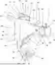
FIG. 1 is a front perspective view of one embodiment of a monolift assembly according to aspects of the disclosure, with a pivoting weight support member shown in a rest position;
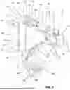
FIG. 2 is a rear perspective view of the monolift assembly of FIG. 1;
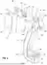
FIG. 3 is a bottom rear perspective view of the monolift assembly of FIG. 1;
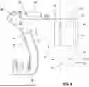
FIG. 4 is a rear perspective view of the monolift assembly of FIG. 1, with the pivoting weight support member shown in a supporting position;
FIG. 5 is a perspective view of the monolift assembly of FIG. 4;
FIG. 6 is a side view of the monolift assembly of FIG. 4 and a post of a weightlifting rack according to aspects of the disclosure;
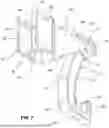
FIG. 7 is a bottom rear perspective view of the monolift assembly of FIG. 4;
FIG. 8 is a bottom perspective view of the monolift assembly of FIG. 4;
FIG. 9 is a side cross-sectional view of the monolift assembly of FIG. 4;
FIG. 10 is a rear perspective view of the monolift assembly of FIG. 4, shown without a gas cylinder;
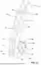
FIG. 11 is a perspective view of the weight support member of the monolift assembly of FIGS. 1 and 4;
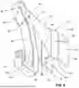
FIG. 12 is a rear perspective view of another embodiment of a monolift assembly according to aspects of the disclosure, with a pivoting weight support member shown in a rest position;
FIG. 13 is a perspective view of the monolift assembly of FIG. 12;
FIG. 14 is a bottom perspective view of the monolift assembly of FIG. 12;
FIG. 15 is a rear perspective view of the monolift assembly of FIG. 12, with a portion removed to show hidden detail;
FIG. 16 is a side cross-section view of the monolift assembly of FIG. 12;
FIG. 17 is a perspective cross-section view of the monolift assembly of FIG. 12;
FIG. 18 is a rear perspective view of the monolift assembly of FIG. 12, with the pivoting weight support member shown in a supporting position;
FIG. 19 is a bottom perspective view of the monolift assembly of FIG. 12;
FIG. 20 is a rear perspective cross-section view of the monolift assembly of FIG. 12; and
FIG. 21 is a rear perspective view of the weight support member of the monolift assembly of FIGS. 12 and 18.
DETAILED DESCRIPTION
While this invention is susceptible of embodiments in many different forms, there are shown in the drawings and will herein be described in detail example embodiments of the invention with the understanding that the present disclosure is to be considered as an exemplification of the principles of the invention and is not intended to limit the broad aspect of the invention to the embodiments illustrated. In the following description of various example structures according to the invention, reference is made to the accompanying drawings, which form a part hereof, and in which are shown by way of illustration various example devices, systems, and environments in which aspects of the invention may be practiced. It is to be understood that other specific arrangements of parts, example devices, systems, and environments may be utilized and structural and functional modifications may be made without departing from the scope of the present invention.
Referring to FIGS. 1-11, a monolift assembly 10 is shown, which is configured for connection to a vertically extending post 12 of a weightlifting assembly, as shown in FIG. 6. The monolift assembly 10 is configured to be removably attached to post 12 as described in greater detail below. A pair of monolift assemblies 10 may be used, in one example, to support a weighted article such as a barbell for weightlifting exercises as described in greater detail below.
An example of a post 12 to which the monolift assembly 10 may be configured for connection is illustrated schematically in FIG. 6. The post 12 in this configuration is a hollow square or rectangular bar (e.g., 3×3 inches or 4×3 inches) formed of a front wall 14, a pair of opposed sidewalls 16, and a rear wall 18, surrounding and defining an interior cavity. The post 12 may include a plurality of post apertures 22 formed in one or more of the front wall 14, the sidewalls 16, and the rear wall 18. FIG. 6 shows post apertures 22 formed in one of the sidewalls 16, with the understanding that the opposing sidewall 16 has corresponding aligned post apertures 22. The front wall 14 and the rear wall 18 also contain aligned post apertures 22. The post apertures 22 in FIG. 6 are all circular, but in certain embodiments, some of the post apertures 22 may be keyhole shaped. The post 12 may be formed of metal, such as steel, for example, but other suitable materials for the post 12 may be used, as recognized by those skilled in the art, given the benefit of this disclosure.
The monolift assembly 10 in the embodiment of FIGS. 1-11 and the monolift assembly 10 in the embodiment of FIGS. 12-21 each includes a carriage assembly 24, a pivoting weight support or pivoting piece 26 pivotally secured to the carriage assembly 24, and a gas cylinder assembly 40 connected to the carriage assembly 24 and the pivoting piece 26 and configured to apply a force to cause pivoting of the pivoting piece 26. Unless otherwise noted herein, the carriage assembly 24 and the pivoting piece 26 may be at least partially formed of metal, such as steel, but other suitable materials may be used, as recognized by those skilled in the art, given the benefit of this disclosure. The pivoting piece 26 is configured to pivot between a rest position, as shown in FIGS. 1-3 and FIGS. 12-17, and a supporting position, as shown in FIGS. 4-10 and 18-20. The rest position is the equilibrium position of the pivoting piece 26, and the gas cylinder assembly 40 exerts a force and/or torque on the pivoting piece 26 to bias the pivoting piece 26 toward the rest position. When a weighted article is engaged with the pivoting piece 26, the force and/or torque exerted by the weighted article exceeds the force and/or torque exerted by the gas cylinder assembly 40, such that the pivoting piece pivots to the support position. It is understood that the monolift assembly 10 may have stop structures and other motion limiting structures to limit the range of motion of the pivoting piece 26. It is also understood that while a gas cylinder assembly 40 (e.g., a pneumatic cylinder) is disclosed as an example herein, other types of pressurized cylinders that rely on fluid pressure to exert an inward (pulling) or outward (pushing) force can be used.
The carriage assembly 24 generally includes a mounting portion 34 configured for mounting to the post 12 and a supporting leg 32 extending outward from the mounting portion 34 for connection to the pivoting piece 26. The carriage assembly 24 may include a first carriage plate 28 and a second carriage plate 30 spaced from first carriage plate 28. Each of the first and second carriage plates 28, 30 includes an arm portion 29 that forms part of the mounting portion 34 and a leg portion 31 extending forward from the arm portion 29 to form part of the supporting leg 32. The arm portions 29 of the first and second carriage plates 28, 30 are offset from each other laterally, such that each of the first and second carriage plates 28, 30 are bent or angled inwardly with respect to the longitudinal centerline of the monolift assembly 10 between the arm portion 29 and the leg portion 31. Each of the arm portions 29 includes a mounting hole 35, such that the mounting holes of the first and second carriage plates 28, 30 are aligned with each other. In another embodiment, the leg portions 31 of the first and/or second carriage plates 28, 30 may include a key slot (not shown) for receiving a key to lock the pivoting piece 26 in position. The pivoting piece 26 in such a configuration would also include a key slot to receive the key. An example of such a key locking arrangement is disclosed in U.S. Patent Application Publication No. 2023/0099317, filed Sep. 28, 2022, which is incorporated by reference herein in its entirety. The first and/or second carriage plates 28, 30 may also include a key storage slot, as also described in US 2023/0099317.
The carriage assembly 24 may also include a connecting plate 44 that extends laterally between the first and second carriage plates 28, 30 and is fixedly connected to the first and second carriage plates 28, 30. The connecting plate 44 in the embodiment of FIGS. 1-11 is formed as an inverted L-shaped plate with a vertical portion 45 and a horizontal portion 46. The vertical portion 45 extends between the two arm portions 29 of the first and second carriage plates 28, 30 at the mounting portion 34 to form a front wall of a channel 27 configured to receive the post 12. The horizontal portion 46 extends between the two leg portions 31 of the first and second carriage plates 28, 30 to form a top surface 54 of the carriage assembly 24. It is understood that the vertical portion 45 and the horizontal portion 46 may be formed by two or more separate plates in another embodiment, e.g., the vertical portion 45 being formed of a vertical plate and the horizontal portion 46 being formed of a horizontal plate. The vertical portion 45 also has a rectangular slot 39 at the bottom thereof, which may receive a portion of the pivoting piece 26 as described herein.
The mounting portion 34 in the embodiment of FIGS. 1-11 includes a channel 27 defined by the two arm portions 29 of the first and second carriage plates 28, 30 and the vertical portion 45 of the connecting plate 46. The channel 27 in this configuration is generally C-shaped. Protective plates or pads 55 are connected to the inner surfaces of the arm portions 29 and the vertical portion 45 to cover the surfaces of the channel 27. The protective plates 55 may be formed of a tough and resilient polymer material, such as a hard plastic or composite material, e.g., a molded plastic piece, to protect both the post 12 and the surfaces of the carriage assembly 24 from damage. The mounting holes 35 on the arm portions 29 also extend through the corresponding protective plates 55. In this configuration, the monolift assembly 10 is mounted on the post 12 by first engaging the mounting portion 34 with the post 12 such that the post 12 is received in the channel 27. In this position, a pin or other connector (not shown) is inserted through the mounting holes 35 and a pair of post apertures 22 in the sidewalls 16 of the post 12, which are aligned with the mounting holes 35. The mounting portion 34 may include additional mounting holes 35 in one embodiment, such as a pair of longitudinally aligned mounting holes 35 in each arm portion 29 that are spaced vertically from each other and spaced such that connectors can be received through both pairs of mounting holes 35 and through two separate pairs of post apertures 22 simultaneously. In the position shown in FIG. 6, the front wall 14 of the post 12 engages the vertical portion 45 of the connecting plate 46 (or the protective plate 55 fixed thereon). It is understood that the front wall 14, the sidewalls 16, and the rear wall 18 of the post 12 are defined relative to the position of the monolift assembly 10, and that the definitions of these walls of the post 12 may change if the position of the monolift assembly 10 is changed.
The mounting portion 34 in other embodiments may have a different configuration. For example, in one embodiment, the mounting portion 34 may use a fixed pin and cup arrangement, such as in a “J-cup” configuration as is known in the art. In another embodiment, the mounting portion 24 may incorporate rollers to allow the monolift assembly to be translated up and down along the post 12. An example of such a configuration is shown and described in U.S. Pat. No. 11,173,337, filed Mar. 6, 2019, and issued on Nov. 16, 2021, which is incorporated by reference herein in its entirety. Other mounting configurations may be used in other embodiments.
The supporting leg 32 extends forward from the mounting portion 34 and supports the pivoting piece 26 at a pivot connection 23 formed by a pivot pin 21 that extends through the pivoting piece 26. A portion of the pivoting piece 26 is received between the leg portions 31 of the first and second carriage plates 28, 30. The horizontal portion 46 of the connecting plate 44 also forms a portion of the supporting leg 32 and terminates short of the distal ends of the leg portions 31 of the first and second carriage plates 28, 30, to provide room for the pivoting piece 26 to pivot above the top surface 54 of the carriage assembly 24. The supporting leg 32 has openings 33 in both of the carriage plates 28, 30 for receiving the pivot pin 21 therethrough.
The pivoting piece 26 may include a main body portion 81 that is pivotably connected to the carriage assembly 24 and an engagement part 82 configured for engaging and supporting a weighted article such as a barbell. The engagement part 82 is in the form of a hook that includes a leg 83 extending forward from the main body portion 81 and a protrusion 85 extending upwardly from the leg 83 to form a substantially J-shaped end of the pivoting piece 26. The main body portion 81, the leg 83, and the protrusion 85 define a notch 89 in the engagement part 82 that is configured to receive a barbell or other weighted article. In certain embodiments, the protrusion 85 may extend substantially perpendicular to the leg 83. The pivoting piece 26 also includes a nose 86 positioned at the opposite end of the main body portion 81 from the engagement part 82, and extending on the opposite side of the pivot connection 23 from the engagement part 82 and other portions of the pivoting piece 26. The nose 86 may provide some counterweight to the engagement part 82 and the other portions of the main body piece 81 on the opposite side of the pivot connection 23, but in the embodiment of FIGS. 1-11, the nose 86 does not provide sufficient weight or leverage to operate as a counterweight as in some existing monolift assemblies. The pivoting piece 26 has a connection positioned on the nose 86 and configured for connection to a gas cylinder assembly 40 as disclosed herein, which connection is formed by a pivot bracket 47 in the embodiment of FIGS. 1-11.
The pivoting piece 26 in FIGS. 1-11 includes two side plates 36 and a frame 37 connected to the two side plates 36 and forming most or all of the outer peripheral surfaces of the pivoting piece 26. The side plates 36 in this configuration are metal plates that reinforce the pivoting piece, and the side plates 36 may be connected by one or more additional metal pieces within the frame 37, as seen in FIG. 9. These additional metal pieces may be located at areas that benefit from increased structural reinforcement. For example, the pivoting piece 26 in FIGS. 1-11 includes a pair of transverse plates 50 located at the nose 86, on top and bottom sides of the pivot connection 23, and a hooked plate 51 located at and around the engagement part 82, which extends around all three sides (front, bottom, and rear) of the notch 89 to reinforce the engagement part 82. In other words, the hooked plate 51 extends downward along the lower end of the main body portion 81, forward along the leg 83, and upward along the protrusion 85. The frame 37 in this configuration is formed of a high strength plastic that protects the pivoting piece 26 and any components contacted by pivoting piece 26 from damage, e.g., the weighted article supported by the pivoting piece 26 and/or the carriage assembly 24. The frame 37 may be formed of multiple pieces in this configuration that are all fixed to the side plates 36 to form the pivoting piece 26. The side plates 36 and the frame 37 both have substantially J-shaped configurations and form portions of the main body portion 81 (including the nose 86) and the engagement part 82 (including the leg 83 and the protrusion 85). The side plates 36 are exposed on the sides of the pivoting piece 26 in this configuration, but the outer surfaces of the side plates 36 are recessed with respect to the frame 37. In this configuration, the frame 37 has recesses 56 on opposite sides thereof, and a lip 57 on each side of the frame 37 extending outward around at least a portion of the periphery of the respective recess 56. The lips 57 may extend around a majority of the periphery of the recesses 56, and in the embodiment of FIGS. 1-11 extend around nearly the entire periphery of the recesses 56, including the entire peripheries of the nose 86 and the main body portion 81 of the pivoting piece 26. The side plates 36 are received in the recesses 56 of the frame 37, and the lips 57 extend around at least a portion of the periphery of the side plates 36. The lips 57 may be substantially flush with the side plates 36 in one embodiment, or the lips 57 may extend outward beyond the side plates 36 in another embodiment, such that the side plates 36 are recessed with respect to the lips 57. The side plates 36 have openings 38 to receive the pivot pin 21 therethrough at the pivot connection 23.
The pivoting piece 26 in FIGS. 1-11 further has a roller 60 rotatably connected to the engagement part 82 within the notch 89, which is configured and positioned such that the weighted article rests on the roller 60 when the weighted article is received in the notch 89 or otherwise engaged with the engagement part 82. The roller 60 in FIGS. 1-11 is rotatably mounted on the pivoting piece 26 by a bolt 61 extending through apertures 62, 63 in the protrusion 85 and the main body portion 81, respectively. These apertures 62, 63 extend through the front and rear portions of the hooked plate 51 in the embodiment of FIGS. 1-11, such that the bolt 61 engages the hooked plate 51 to provide reinforcement to the mounting of the roller 60. The bolt 61 defines an axis of rotation for roller 60 that extends substantially parallel to the leg 83 and perpendicular or otherwise transverse to the surfaces of the protrusion 85 and the main body portion 81 defining the notch 89. The bolt 61 engages the pivoting piece 26 by a threaded connection, as seen in FIG. 9. The roller 60 has a contoured surface that is rotationally symmetrical with respect to the axis of rotation defined by bolt 61. The roller 60 in this embodiment has a circumferential recess 69 that is recessed radially inward from the adjacent portions of the roller 60 to receive a portion of the weighted article. The recess 69 has a smoothly curved contour. The protrusion 85 and/or the main body portion 81 may engage the weighted article when received in the notch 89 as well. Rotation of the roller 60 reduces friction and stress on the monolift assembly 10 when moving the weighted article laterally, facilitating adjusting position of the weighted article while engaged with and supported by the pivoting piece 26.
In other embodiments, the pivoting piece 26 may be configured, in whole or in part, similarly to the pivoting pieces disclosed in previously-mentioned US 2023/0099317, which is incorporated by reference herein. For example, the pivoting piece 26 may have a construction as disclosed in US 2023/0099317 in one embodiment. As another example, the pivoting piece 26 may have a construction as disclosed herein, but with a weight support in the form of a fixed hook, such as disclosed in US 2023/0099317, rather than incorporating a roller 60. Other components and features of the disclosure of US 2023/0099317 may be incorporated into embodiments of the monolift assembly 10 disclosed herein.
The monolift assembly 10 of FIGS. 1-11 has a gas cylinder assembly 40 that exerts a force on the pivoting piece 26 to bias the pivoting piece 26 to pivot so the engagement portion 82 moves rearwardly (counterclockwise in FIG. 6). The gas cylinder assembly 40 in this embodiment exerts a pushing force on the pivoting piece 26 to achieve this condition. In this embodiment, the gas cylinder assembly 40 has a first end 41 that is connected to the carriage assembly 24 and a second end 42 connected to the pivoting piece 26. The second end 42 of the gas cylinder assembly 40 is connected to the pivoting piece 26 at a point that is spaced from the pivot connection 23 and the pivot pin 21, such that the gas cylinder assembly 40 exerts a torque on the pivoting piece 26 to induce rotation about the pivot connection 23. The first end 41 in the embodiment of FIGS. 1-11 is a fixed end and is connected to a first bracket 43 that is fixed to the top surface 54 of the carriage assembly 24. The first bracket 43 is fixed to the horizontal portion 46 of the connecting plate 44 in one embodiment. The second end 42 in the embodiment of FIGS. 1-11 is a moveable end that is moveable with respect to the fixed end and is connected to a second bracket 47 that is fixed to the nose 86 of the main body 81 of the pivoting piece 26. The gas cylinder assembly 40 exerts an outward force to push the second end 42 away from the first end 41, thereby exerting a force and a torque on the pivoting piece 26. In general, the second end 42 of the gas cylinder assembly 40 may be fixed to the nose 86 of the pivoting piece 26 or anywhere between the nose 86 and the pivot connection 23 in various embodiments, in order to achieve a torque in the correct rotational direction. The connections between the first and second ends 41, 42 and the first and second brackets 43, 47 are pivoting connections created by a ball and socket arrangement, as seen in FIGS. 9-10. The gas cylinder assembly 40 in this embodiment includes a pressurized gas cylinder 48 connected to the first end 41 and a moveable piston 49 connected to the second end 42. Moving the second end 42 toward the first end 41 causes the piston 49 to retract into the gas cylinder 48, such that the gas cylinder 48 exerts an outward force on the piston 49 to push the pivoting piece 26 toward the rest position. In another embodiment, the arrangement of the gas cylinder 48 and the piston 49 may be transposed, such that the piston 49 is connected to the first end 41 and the gas cylinder 48 is connected to the second end 42.
When a weighted article is engaged with the engagement part 82 of the pivoting piece 26, a force and a torque are exerted on the pivoting piece 26 to cause the pivoting piece 26 to pivot to the support position, where the engagement part 82 can more effectively support the weighted article. In the support position, shown in FIGS. 4-10, the leg 83 and the roller 60 are both oriented approximately parallel to the ground, and the portions of the main body portion 81 and the protrusion 85 defining the channel 27 extend substantially straight upward, to provide the most secure support for the weighted article. For the pivoting piece 26 to pivot from the rest position to the support position, the pivoting piece 26 pivots so the engagement portion 82 moves forwardly (clockwise in FIG. 6). It is understood that the pivoting piece 26 will pivot to the support position when the torque exerted by the weighted article exceeds the torque exerted by the gas cylinder assembly 40. When the weighted article is removed from the engagement part 82, the gas cylinder assembly 40 causes the pivoting piece 26 to pivot to the rest position, thereby minimizing the risk of the user inadvertently bumping into monolift assembly 10 during use.
FIGS. 12-21 illustrate another example embodiment of a monolift assembly 10 that includes many components and features in common with the monolift assembly 10 in FIGS. 1-11 and functions in a somewhat similar manner. As such, the components, features, and functionality of the monolift assembly 10 in FIGS. 12-21 that have already been described with respect to the embodiment of FIGS. 1-11 may not be fully described in detail herein, and corresponding components may not all be indicated by reference numbers in the drawing figures, for the sake of brevity and conciseness. In general, the monolift assembly 10 in FIGS. 12-21 is similar to that described previously, but uses a gas cylinder assembly 40 that exerts a pulling force on the pivoting piece 26, rather than a pushing force as in the embodiment of FIGS. 1-11.
The carriage assembly 24 of the embodiment of FIGS. 12-21 is generally similar or identical to the carriage assembly 24 in the embodiment of FIGS. 1-11 in almost all aspects. The structures supporting the mounting configuration of the gas cylinder assembly 40 in the embodiment of FIGS. 12-21 are different from those in the embodiment of FIGS. 1-11. The carriage assembly 24 in FIGS. 12-21 has a first bracket 43 that is fixed to the top surface 54 of the carriage assembly 24, and a connecting plate 44 having a vertical portion 45 and a horizontal portion 46 that defines the top surface 54. The first bracket 43 in this embodiment is positioned farther forward than in the embodiment of FIGS. 1-11, and is located at or near the front end of the horizontal portion 46 of the connecting plate 44. The horizontal portion 46 also has an opening 53 that permits the gas cylinder assembly 40 to extend downward through the connecting plate 44 to engage the pivoting piece 26. The opening 53 in this embodiment is a semicircular-shaped hole that is cut in the horizontal portion 46 of the connecting plate 44, but in another embodiment, the opening 53 may be differently configured, such as by having a different shape or being a complete gap within the structure of the connecting plate 44. Additionally, the first bracket 43 is connected to the connecting plate 44 in this embodiment to extend across the opening 53, by having a portion received within the opening 53 and engaging the connecting plate 44 within the opening 53.
Additional components in the embodiment of FIGS. 12-21 are not illustrated in the drawings, but may be incorporated into this embodiment using the same or similar structures to the components of the embodiment of FIGS. 1-11, or other embodiments. For example, FIGS. 12-21 do not illustrate any protective plates or pads 55 surrounding the channel 27 of the mounting portion 34 of the carriage assembly 24 in FIGS. 12-21. However, it is understood that the carriage assembly 24 of FIGS. 12-21 may have protective plates or pads 55 surrounding the channel 27 and connected to the inner surfaces of the arm portions 29 and the vertical portion 45 to cover the surfaces of the channel 27. Such pads 55 may be structured similarly to the pads 55 illustrated in FIGS. 1-11 and described herein with respect to that embodiment. As another example, the carriage assembly 24 in FIGS. 12-21 is shown without a pivot pin 21, with the understanding that the carriage assembly 24 is designed to receive and use a pivot pin 21 that is similar or identical to the pivot pin 21 in FIGS. 1-11.
The pivoting piece 26 in FIGS. 12-21 also has a structure that is generally similar or identical in most aspects to the pivoting piece 26 in FIGS. 1-11. In FIGS. 12-21, the pivoting piece 26 includes two side plates 36 and one or more additional metal pieces connected to the side plates 36, including a hooked plate 51 located at the distal end of the engagement part 82 around the notch 89. The second bracket 47 is connected directly to the hooked plate 51 in this configuration. The one or more additional metal pieces forming the structure of the pivoting piece 26 in the embodiment of FIGS. 12-21 may also include a pair of transverse plates 50 located at the nose 86, on top and bottom sides of the pivot connection 23, as similarly shown in FIGS. 1-11. The pivoting piece 26 in this embodiment also includes a frame similar to the frame 37 of FIGS. 1-11, connected to the two side plates 36 and forming most or all of the outer peripheral surfaces of the pivoting piece 26, but the frame is not illustrated in FIGS. 12-21 to show additional detail of the pivoting piece 26. Nevertheless, it is noted that, in this embodiment, the frame has an opening (not shown) on the rear side of the main body portion 81 to permit the gas cylinder assembly 40 to extend through the frame to engage the hooked plate 51. In another embodiment, the gas cylinder assembly 40 may engage a different portion of the pivoting piece 26, and the frame may be differently configured.
The gas cylinder assembly 40 in the embodiment of FIGS. 12-21 is configured such that the gas cylinder assembly 40 exerts a pulling force on the pivoting piece 26. Accordingly, the positions of the first end 41 and the second end 42 of the gas cylinder assembly 40, as well as their connections to the carriage assembly 24 and the pivoting piece 26, are arranged differently from the embodiment of FIGS. 1-11.
The first end 41 of the gas cylinder assembly 40 in the embodiment of FIGS. 12-21 is a fixed end and is connected to the first bracket 43, which is fixed to the top surface 54 of the carriage assembly 24. The first bracket 43 is fixed to the horizontal portion 46 of the connecting plate 44 in one embodiment. The second end 42 of the gas cylinder assembly 40 in the embodiment of FIGS. 12-21 is a moveable end that is moveable with respect to the fixed end and is connected to a second bracket 47 that is fixed to the main body 81 of the pivoting piece 26 proximate the engagement part 82. In the embodiment of FIGS. 12-21, the second end 42 of the gas cylinder assembly 40 is fixed directly to the hooked plate 51, but the second end 42 may be fixed to other portions of the pivoting piece 26 in other embodiments. The gas cylinder assembly 40 exerts an inward force to pull the second end 42 toward the first end 41, thereby exerting a force and a torque on the pivoting piece 26. In general, the second end 42 of the gas cylinder assembly 40 may be fixed to the engagement part 82 of the pivoting piece 26 or anywhere between the engagement part 82 and the pivot connection 23 in various embodiments, in order to achieve a torque in the correct rotational direction. The connections between the first and second ends 41, 42 and the first and second brackets 43, 47 are pivoting connections created by a ball and socket arrangement, as seen in FIGS. 16-17. The gas cylinder assembly 40 in this embodiment includes a pressurized gas cylinder 48 connected to the first end 41 and a moveable piston 49 connected to the second end 42. Moving the second end 42 away from the first end 41 causes the piston 49 to extend out of the gas cylinder 48, such that the gas cylinder 48 exerts an inward force on the piston 49 to pull the pivoting piece 26 toward the rest position. In another embodiment, the arrangement of the gas cylinder 48 and the piston 49 may be transposed, such that the piston 49 is connected to the first end 41 and the gas cylinder 48 is connected to the second end 42.
When a weighted article is engaged with the engagement part 82 of the pivoting piece 26, a force and a torque are exerted on the pivoting piece 26 to cause the pivoting piece 26 to pivot to the support position, where the engagement part 82 can more effectively support the weighted article. In the support position, shown in FIGS. 18-20, the leg 83 and the roller 60 are both oriented approximately parallel to the ground, and the portions of the main body portion 81 and the protrusion 85 defining the channel 27 extend substantially straight upward, to provide the most secure support for the weighted article. For the pivoting piece 26 to pivot from the rest position to the support position, the pivoting piece 26 pivots so the engagement portion 82 moves forwardly (clockwise in FIG. 16). It is understood that the pivoting piece 26 will pivot to the support position when the torque exerted by the weighted article exceeds the torque exerted by the gas cylinder assembly 40. When the weighted article is removed from the engagement part 82, the gas cylinder assembly 40 causes the pivoting piece 26 to pivot to the rest position, thereby minimizing the risk of the user inadvertently bumping into monolift assembly 10 during use.
Various embodiments of monolift assemblies have been described herein, which include various components and features. In other embodiments, the monolift assemblies may be provided with any combination of such components and features. It is also understood that in other embodiments, the various devices, components, and features of the monolift assemblies described herein may be constructed with similar structural and functional elements having different configurations, including different ornamental appearances.
The monolift assembly 10 as disclosed herein provides benefits and advantages over existing monolift assemblies and similar articles for use in weightlifting. For example, the use of a gas cylinder to provide the force and torque to return the pivoting piece to the rest position avoids the need for a counterweight to achieve rotation back to the rest position. This provides increased safety and comfort in use, as such counterweights may project forward a significant distance, where they may be impacted by the user and cause injury or disruption of the weightlifting exercise. This also can reduce the overall weight of the monolift assembly 10. As another example, the mounting structure for the gas cylinder assembly 40 provides a simple, effective, and durable configuration. As a further example, the structure of the pivoting piece 26 provides a strong and durable construction that is efficient to manufacture and assemble. Still other benefits and advantages are recognizable by those skilled in the art upon reading this disclosure.
Several alternative embodiments and examples have been described and illustrated herein. A person of ordinary skill in the art would appreciate the features of the individual embodiments, and the possible combinations and variations of the components. A person of ordinary skill in the art would further appreciate that any of the embodiments could be provided in any combination with the other embodiments disclosed herein. It is understood that the invention may be embodied in other specific forms without departing from the spirit or central characteristics thereof. The present examples and embodiments, therefore, are to be considered in all respects as illustrative and not restrictive, and the invention is not to be limited to the details given herein. The terms “top,” “bottom,” “front,” “back,” “side,” “rear,” “proximal,” “distal,” and the like, as used herein, are intended for illustrative purposes only and do not limit the embodiments in any way. Nothing in this specification should be construed as requiring a specific three dimensional orientation of structures in order to fall within the scope of this invention, unless explicitly specified by the claims. When used in description of a method or process, the term “providing” (or variations thereof) as used herein means generally making an article available for further actions, and does not imply that the entity “providing” the article manufactured, assembled, or otherwise produced the article. The terms “approximately” or “substantially” as used herein implies a variation of up to 10% of the nominal value or property modified by such term, or up to 10% of a midpoint value of a range modified by such term. “Integral joining technique,” as used herein, means a technique for joining two pieces so that the two pieces effectively become a single, integral piece, including, but not limited to, irreversible joining techniques such as welding, brazing, soldering, or the like, where separation of the joined pieces cannot be accomplished without structural damage thereto. Additionally, the term “plurality,” as used herein, indicates any number greater than one, either disjunctively or conjunctively, as necessary, up to an infinite number. Accordingly, while the specific embodiments have been illustrated and described, numerous modifications come to mind without significantly departing from the spirit of the invention and the scope of protection is only limited by the scope of the accompanying claims.
Claims
What is claimed is:1. A monolift assembly comprising:
a carriage assembly comprising a mounting portion configured for mounting to a post and a supporting leg connected to the mounting portion and extending outward from the mounting portion;
a pivoting piece comprising a main body portion pivotably connected to the supporting leg of the carriage assembly at a pivot connection and an engagement part connected to the main body portion, wherein the pivoting piece is pivotable between a rest position, where the engagement part is retracted, and a supporting position, where the engagement part is extended, such that the engagement part is configured for engaging and supporting a weighted article in the supporting position; and
a pressurized cylinder assembly having a first end engaged with the carriage assembly and a second end engaged with the pivoting piece at a location spaced from the pivot connection, the pressurized cylinder assembly comprising a pressurized cylinder configured to exert a torque on the pivoting piece by fluid pressure within the pressurized cylinder to induce rotation of the pivoting piece about the pivot connection and bias the pivoting piece toward the rest position, such that the rest position is an equilibrium position of the pivoting piece.
2. The monolift assembly of claim 1, wherein the pressurized cylinder is a gas cylinder.
3. The monolift assembly of claim 1, wherein the pivoting piece further comprises a nose extending forward from the main body portion beyond the pivot connection, and the engagement part is connected to the main body portion on an opposite side of the pivot connection from the nose, and wherein the second end of the pressurized cylinder assembly is engaged with the nose of the pivoting piece.
4. The monolift assembly of claim 1, wherein the pivoting piece further comprises a nose extending forward from the main body portion beyond the pivot connection, and the engagement part is connected to the main body portion on an opposite side of the pivot connection from the nose, and wherein the second end of the pressurized cylinder assembly is engaged with the main body portion of the pivoting piece below the pivot connection.
5. The monolift assembly of claim 1, wherein the pressurized cylinder assembly is configured to exert the torque on the pivoting piece by exerting a pushing force on the pivoting piece.
6. The monolift assembly of claim 1, wherein the pressurized cylinder assembly is configured to exert the torque on the pivoting piece by exerting a pulling force on the pivoting piece.
7. The monolift assembly of claim 1, wherein the carriage assembly further comprises a first carriage plate and a second carriage plate spaced from each other, the first and second carriage plates each having a leg portion forming at least a portion of the supporting leg, wherein the pivoting piece is positioned such that the main body portion extends between the first carriage plate and the second carriage plate and is pivotably connected to the leg portions of the first carriage plate and the second carriage plate.
8. The monolift assembly of claim 7, wherein the carriage assembly further comprises a connecting plate extending horizontally between the first carriage plate and the second carriage plate and defining at least a portion of a top surface of the carriage assembly, wherein the first end of the pressurized cylinder assembly is connected to connecting plate at the top surface of the carriage assembly.
9. The monolift assembly of claim 7, wherein the first carriage plate and the second carriage plate each further include an arm portion forming part of the mounting portion of the carriage assembly, and wherein the mounting portion comprises a channel configured to receive the post, and the arm portions of the first carriage plate and the second carriage plate define sides of the channel.
10. The monolift assembly of claim 1, wherein the engagement part further comprises a notch configured for receiving the weighted article when the pivoting piece is in the supporting position, wherein the pivoting piece further comprises a roller rotatably connected to the engagement part within the notch, and wherein the roller is configured and positioned to support the weighted article when the weighted article is received in the notch, such that the weighted article rests on the roller.
11. A monolift assembly comprising:
a carriage assembly comprising a mounting portion configured for mounting to a post and a supporting leg connected to the mounting portion and extending outward from the mounting portion; and
a pivoting piece comprising a main body portion pivotably connected to the supporting leg of the carriage assembly at a pivot connection, a nose extending forward from the main body portion beyond the pivot connection, and an engagement part connected to the main body portion on an opposite side of the pivot connection from the nose, the engagement part comprising a leg extending forward from the main body portion and a protrusion extending upward from the leg to define a notch, and wherein the pivoting piece is pivotable between a rest position, where the engagement part is retracted, and a supporting position, where the engagement part is extended, such that the engagement part is configured for engaging and supporting a weighted article in the supporting position by receiving the weighted article within the notch, wherein the pivoting piece further comprises:
a frame formed of a polymer material and defining portions of the main body portion, the nose, and the engagement part, including the leg and the protrusion, wherein the frame has a first recess and a second recess on opposite sides of the frame, a first lip extending outwardly around at least a portion of a periphery of the first recess, and a second lip extending outwardly around at least a portion of a periphery of the second recess;
a first side plate formed of a metallic material, the first side plate received in the first recess and extending into the main body portion, the nose, and the engagement part, including the leg and the protrusion, such that the first lip extends around at least a portion of a periphery of the first side plate; and
a second side plate formed of the metallic material, the second side plate received in the second recess and extending into the main body portion, the nose, and the engagement part, including the leg and the protrusion, such that the second lip extends around at least a portion of a periphery of the second side plate, and the frame separates the first side plate from the second side plate.
12. The monolift assembly of claim 11, further comprising a pressurized cylinder assembly engaged with the carriage assembly and engaged with the pivoting piece at a location spaced from the pivot connection, the pressurized cylinder assembly comprising a pressurized cylinder configured to exert a torque on the pivoting piece by fluid pressure within the pressurized cylinder to induce rotation of the pivoting piece about the pivot connection and bias the pivoting piece toward the rest position.
13. The monolift assembly of claim 11, wherein the pivoting piece further comprises a roller rotatably connected to the engagement part within the notch, and wherein the roller is configured and positioned to support the weighted article when the weighted article is received in the notch, such that the weighted article rests on the roller.
14. The monolift assembly of claim 11, wherein the carriage assembly further comprises a first carriage plate and a second carriage plate spaced from each other, the first and second carriage plates each having a leg portion forming at least a portion of the supporting leg, wherein the pivoting piece is positioned such that the main body portion extends between the first carriage plate and the second carriage plate and is pivotably connected to the leg portions of the first carriage plate and the second carriage plate.
15. The monolift assembly of claim 14, wherein the pivoting piece further comprises a hooked plate connected to the frame and positioned between the first carriage plate and the second carriage plate, wherein the hooked plate is a metallic plate extending from the main body portion through the leg and into the protrusion of the engagement part, around the notch.
16. A monolift assembly comprising:
a carriage assembly comprising a mounting portion configured for mounting to a post and a supporting leg connected to the mounting portion and extending outward from the mounting portion, wherein the carriage assembly further comprises a first carriage plate and a second carriage plate spaced from each other, the first and second carriage plates each having a leg portion forming at least a portion of the supporting leg and an arm portion forming part of the mounting portion of the carriage assembly, and wherein the mounting portion comprises a channel configured to receive the post, and the arm portions of the first carriage plate and the second carriage plate define sides of the channel;
a pivoting piece comprising a main body portion pivotably connected to the supporting leg of the carriage assembly at a pivot connection, wherein the pivoting piece is positioned such that the main body portion extends between the first carriage plate and the second carriage plate and is pivotably connected to the leg portions of the first carriage plate and the second carriage plate, a nose extending forward from the main body portion beyond the pivot connection, and an engagement part connected to the main body portion on an opposite side of the pivot connection from the nose, the engagement part comprising a leg extending forward from the main body portion and a protrusion extending upward from the leg to define a notch, wherein the pivoting piece is pivotable between a rest position, where the engagement part is retracted, and a supporting position, where the engagement part is extended, such that the engagement part is configured for engaging and supporting a weighted article in the supporting position by receiving the weighted article within the notch; and
a pressurized cylinder assembly having a first end engaged with the carriage assembly and a second end engaged with the pivoting piece at a location spaced from the pivot connection, the pressurized cylinder assembly comprising a pressurized cylinder configured to exert a torque on the pivoting piece by fluid pressure within the pressurized cylinder to induce rotation of the pivoting piece about the pivot connection and bias the pivoting piece toward the rest position, such that the rest position is an equilibrium position of the pivoting piece.
17. The monolift assembly of claim 16, wherein the second end of the pressurized cylinder assembly is engaged with the nose of the pivoting piece, and wherein the pressurized cylinder assembly is configured to exert the torque on the pivoting piece by exerting a pushing force on the nose of the pivoting piece.
18. The monolift assembly of claim 16, wherein the second end of the pressurized cylinder assembly is engaged with the main body portion of the pivoting piece below the pivot connection, and wherein the pressurized cylinder assembly is configured to exert the torque on the pivoting piece by exerting a pulling force on the main body portion of the pivoting piece.
19. The monolift assembly of claim 16, wherein the pivoting piece further comprises a roller rotatably connected to the engagement part within the notch, and wherein the roller is configured and positioned to support the weighted article when the weighted article is received in the notch, such that the weighted article rests on the roller.
20. The monolift assembly of claim 16, wherein the pivoting piece further comprises:
a frame formed of a polymer material and defining portions of the main body portion, the nose, and the engagement part, including the leg and the protrusion, wherein the frame has a first recess and a second recess on opposite sides of the frame, a first lip extending outwardly around at least a portion of a periphery of the first recess, and a second lip extending outwardly around at least a portion of a periphery of the second recess;
a first side plate formed of a metallic material, the first side plate received in the first recess and extending into the main body portion, the nose, and the engagement part, including the leg and the protrusion, such that the first lip extends around at least a portion of a periphery of the first side plate; and
a second side plate formed of the metallic material, the second side plate received in the second recess and extending into the main body portion, the nose, and the engagement part, including the leg and the protrusion, such that the second lip extends around at least a portion of a periphery of the second side plate, and the frame separates the first side plate from the second side plate.
Images & Drawings included:


Sources:
- United States Patent and Trademark Office - verify current appl. status at the USPTO↗
Similar patent applications:
- » 20230099317
Monolift rack assembly - » 20250269226
MONOLIFT RACK ASSEMBLY
Recent applications in this class:
- » 20250332466 2025-10-30
BENCH PRESS EXERCISE SUPPORTING SYSTEM - » 20250295947 2025-09-25
BENCH PRESS NON-SLIP MAT - » 20250256149 2025-08-14
TROLLEY ASSEMBLY AND WEIGHT ARM - » 20250205543 2025-06-26
Weightlifting Rack Assembly and Wall Mount Bracket for a Weightlifting Rack Assembly - » 20250010123 2025-01-09
Assembly for Weightlifting Racks - » 20250010122 2025-01-09
Weight Bar Holding Apparatus for Weightlifting Rack - » 20240307729 2024-09-19
TILTING SMITH EXERCISE MACHINE WITH MOVABLE STRUCTURES - » 20240245948 2024-07-25
Exercise Apparatus - » 20240189650 2024-06-13
Multifunctional comprehensive training device capable of being grasped stably - » 20240100385 2024-03-28
Modular power rack attachment for facilitating loaded barbell height adjustment