Racket Guard
US20250352863A1
2025-11-20
19/174,549
2025-04-09
Smart Summary: A racket guard is a protective cover designed for the end of a sports racket. It is made from a strong yet flexible material that can easily fit onto the racket without any screws or fasteners. The guard has an oval shape and covers about half of the racket's frame to shield it from impacts, like hitting the ground. It is lightweight and does not add extra weight or change how the racket feels during play. If it gets damaged, it can be quickly taken off and replaced with a new one. 🚀 TL;DR
Abstract:
A racket guard formed from a sturdy, durable, lightweight, yet flexible, material, such as a thermoplastic urethane, can be mounted on the distal end of a sports racket without the use of fasteners to protect the frame of the racket from accidental impacts, such as against the playing surface, during use of the sports racket. The cross-sectional shape of the racket guard is an oval configuration with an outer band that overlies the frame and includes side walls and inwardly directed flanges that terminate in a spaced relationship defining a gap through which the frame can pass by flexing the flanges. The racket guard is preferably sized to cover about 180 degrees of the sports racket to provide protection for the sides of the frame. The lightweight racket guard does not serve as a weight or as a dampening device. If damaged, the racket guard is easily removed and replaced.
Applicant:
Interested in similar patents?
Get notified when new applications in this technology area are published.
Classification:
A63B49/14 » CPC main
Stringed rackets, e.g. for tennis; Frames Protection devices on the frame
A63B2102/02 » CPC further
Application of clubs, bats, rackets or the like to the sporting activity ; particular sports involving the use of balls and clubs, bats, rackets, or the like Tennis
Description
CROSS-REFERENCE TO RELATED APPLICATIONS
This application claims domestic priority on co-pending U.S. Provisional Patent Application Ser. No. 63/649,234, filed on May 17, 2024, the content of which is incorporated herein by reference.
FIELD OF THE INVENTION
This invention relates generally to a device to protect the frame of a sports racket used in sports such as tennis, squash, racket ball, badminton and the like, and, more particularly, to a device formed from a plastic material and selectively positionable onto the distal end of the racket to be used for protection of the racket upon impact with a solid surface.
BACKGROUND OF THE INVENTION
People playing sports utilizing a racket that is wielded to strike an object to return the object to the opposing player, usually over a net separating the players, often strike the distal end of the racket against an object, such as the court, ground, wall, etc., resulting in damage to the frame of the racket at the distal end thereof. High end rackets, such as tennis rackets, can cost hundreds of dollars, and if the frame thereof is damaged, repair of the racket, for all players from beginners to high end players, is not an effective option. Thus, discarding the damaged racket and purchasing a new racket is typically the option to resolve the problem of a damaged racket.
A number of patents are known in the art for the attachment of weights to various locations on the racket to change the dynamics of the swing of the racket. An example of weighted attachments for a racket is found in U.S. Pat. No. 8,758,175, granted to Kuo-Pin Yu on Jun. 24, 2014, wherein the outer surface of the racket frame is formed to receive at least one weighted strip that is attached to the racket frame by a screw. The racket frame is formed in a manner to enable the connection of the weight or weights to selected portions of the racket frame for advantageous utilization of the weights.
In U.S. Pat. No. 8,968,125, granted to Head Technology GmbH, on Mar. 3, 2015, the racket frame is formed with selected locations of the frame, such as at the 9, 12 and 3 o'clock positions, at which weights can be added, including portions of increased density of the frame. In U.S. Patent Publication No. 2012/0220398, published on Aug. 30, 2012, by Ronald T. Martino, an attachment is detachable on selected portions of the outer surface of the racket frame to provide a brush that can be used for sweeping debris from the surface of the court playing surface and to clean the boundary lines of the tennis court. The attachment is formed with an H-shaped frame in which the cross member retains the brush fibers, and the legs are spaced to fit around the width of the racket frame.
U.S. Patent Publication No. 2024/0131407, published on Apr. 25, 2024, by GAMEFACEGEAR, LLC, discloses a paddle bumper for encasing a paddle, such as a pickle ball paddle, to extend the life of the paddle, to protect the exterior edges of the paddle from damage, and to reduce vibrations during use of the paddle. The preferred embodiment of the paddle bumper is one that encases the paddle, including opposing lateral side portions and a handle portion. The cross-section of the paddle bumper is formed in a U-shaped configuration to encompass the outside surface and the edges of the paddle on which the paddle bumper is mounted.
A silicone-based material is formed into a device that can be mounted on the outer surface of a racket frame through a fastening member, such as an adhesive backing is disclosed in U.S. Pat. No. 7,946,937, issued on May 24, 2011, to Benjamin M. Searle. The device of the '937 patent is formed as a flat strip without any portion thereof overlying the side surfaces of the racket frame. This device is simply adhered to the outer edge of the racket frame and would provide limited protection from a player impacting the frame of the racket into a court, playing surface, wall, etc.
It would be desirable to provide a racket guard that can be mounted onto the frame of a sports racket that will provide protection for the frame of the racket if impacted into a solid object, such as a playing surface. It would also be desirable that the racket guard be capable of mounting onto the frame without requiring fasteners. It would further be desirable to form the racket guard in a manner to protect the frame from impacts against the sides of the frame.
SUMMARY OF THE INVENTION
It is an object of this invention to overcome the disadvantages of the known prior art by providing a detachable guard for the distal end of a sports racket.
It is another object of this invention to provide a detachable guard that protects the frame of the sports racket if impacted into a solid object, such as a playing surface.
It is a feature of this invention that the racket guard can be mounted onto the frame of the sports racket without requiring fasteners that engage the racket frame.
It is an advantage of this invention that the frame of the sports racket is not weakened by the installation of fasteners that secure a racket guard to the frame of the sports racket.
It is another feature of this invention that the racket guard is formed from a thermoplastic urethane, or other similar material, having a preferable thickness in the range of 0.03 to 0.08 inch.
It is another advantage of this invention that the racket guard provides a sturdy, flexible structure mounted on the frame of the sports racket.
It is still another feature of this invention that the arcuate shape of the racket guard is shaped to match the oval curvature of the racket frame.
It is still another advantage of this invention that the racket guard mounted on the distal end of a sports racket helps to keep the racket guard in position during play with the sports racket.
It is yet another feature of this invention that the weight of the racket guard is minimal compared to the overall weight of the sports racket.
It is yet another advantage of this invention that the racket guard does not serve as a weight or dampening device on the racket.
It is a further advantage of this invention that an impact of the distal end of the racket with a solid structure, like the playing court, will be absorbed by the racket guard protecting the distal end of the racket, and the outer surface of the frame.
It is still a further advantage of this invention that the operative life of sports rackets can be extended without requiring repairs or replacements.
It is a further feature of this invention that the racket guard can cover about 180 degrees of the racket frame including the distal end of the racket to provide protection for the sides of the sports racket.
It is still a further feature of this invention that the cross-sectional shape of the racket guard is an oval configuration with an outer band that overlies the outside surface of the frame of the sports racket.
It is yet a further feature of this invention that the cross-sectional shape of the racket guard incorporates a pair of opposing side walls extending from an outer band and a pair of inwardly directed flanges inwardly directed from the side walls to terminate in a spaced relationship on opposing sides of the sports racket strings and spanning the racket frame, thus defining a gap between the terminal ends of the flanges.
It is yet a further advantage of this invention that the relationship between the side walls and the flanges enables the flanges to bend outwardly sufficiently to pass over the width of the racket frame to allow the racket guard to be mounted onto the distal end of the racket frame with the flanges return to their normal position after being placed onto the frame to secure the racket guard on the sports racket.
It is a further object of this invention to provide a racket guard for mounting on a sports racket that is durable in construction, carefree of maintenance, easily mounted onto the racket frame, and simple and effective in use.
These and other objects, features and advantages are accomplished according to the instant invention by providing a racket guard formed from a sturdy, durable, lightweight, yet flexible, material, such as a thermoplastic urethane, that can be mounted on the distal end of a sports racket without the use of fasteners to protect the frame of the racket from accidental impacts, such as against the playing surface, during use of the sports racket. The cross-sectional shape of the racket guard is an oval configuration with an outer band that overlies the frame and includes side walls and inwardly directed flanges that terminate in a spaced relationship defining a gap through which the frame can pass by flexing the flanges. The racket guard is preferably sized to cover about 180 degrees of the sports racket to provide protection for the sides of the frame. The lightweight racket guard does not serve as a weight or as a dampening device. If damaged, the racket guard is easily removed and replaced.
BRIEF DESCRIPTION OF THE DRAWINGS
The advantages of this invention will be apparent upon consideration of the following detailed disclosure of the invention, especially when taken in conjunction with the accompanying drawings wherein:
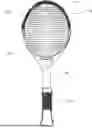
FIG. 1 is a schematic elevational view of a representative tennis racket having a racket guard incorporating the principles of the instant invention mounted thereon;
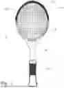
FIG. 2 is an enlarged schematic elevational view of the racket guard shown in FIG. 1;
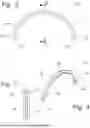
FIG. 3 is an enlarged cross-sectional view of the racket guard corresponding to lines 3-3 of FIG. 2; and
FIG. 4 is a perspective view of the racket guard.
DETAILED DESCRIPTION OF THE PREFERRED EMBODIMENT
Referring to FIGS. 1-4, a racket guard incorporating the principles of the instant invention can best be seen. FIG. 1 depicts a representative tennis racket having a racket guard 10 mounted on the distal end of the racket R. One skilled in the art will recognize that the representative racket R could be any sports racket, including, but not limited to, a tennis racket, a paddle ball racket, a squash racket, a pickle ball racket, and a badminton racket, which are exposed to being impacted into a non-yielding object, including the playing court. The purpose of the racket guard 10 is to overlie the outside surface of the frame F of the racket R, as well as the sides S of the frame F, and protect the frame F from being damaged by impacts to the frame F. One skilled in the art will recognize that the racket R has a head H that incorporates the frame F and terminates in a handle having a grip G by which the racket R is used to play games such as tennis or pickle ball.
As is best seen in FIGS. 2-4, the racket guard 10 preferably covers about 180 degrees of the racket frame F corresponding to the distal end of the racket R. The cross-sectional shape of the racket guard 10 is somewhat of an oval with an outer band 11 to overlie the outside surface of the frame F, a pair of opposing side walls 12 extending from the outer band 11, and a pair of inwardly directed flanges 13 integrally directed from the side walls 12 to terminate in a spaced relationship on opposing sides of the strings S spanning the frame F of the racket R, defining a gap 15 between the terminal ends of the flanges 13. The relationship between the side walls 12 and the flanges 13 enables the flanges 13 to bend outwardly sufficiently to pass over the width of the frame F and allow the racket guard 10 to be mounted onto the distal end of the frame F. The flanges 13 return to their normal position after being placed onto the frame F to secure the racket guard on the racket R.
Preferably, the racket guard 10 is formed from a thermoplastic urethane, or other similar material, having a preferable thickness in the range of 0.03 to 0.08 inch, providing a sturdy, yet flexible, structure that does not require a fastener to be secured to the frame F of the racket R. The arcuate shape of the racket guard 10 is shaped to match the oval curvature of the racket frame F, which helps to keep the racket guard 10 in position on the distal end of the frame F during play with the racket R. The overall weight of the racket guard 10 is minimal compared to the weight of the racket R, so that the racket guard 10 does not serve as a weight or dampening device on the racket R.
Installation of the racket guard 10 is accomplished by wedging the frame F of the racket R into the gap 15 at one end of the racket guard 10, forcing the flanges apart so that the width of the frame F can pass through the gap 15 and into the cavity defined by the outer band 11, side walls 12 and flanges 13. Once the end of the racket frame F has been positioned into the aforesaid cavity, further installation is accomplished by pressing along the arcuate length of the racket guard 10, spreading the flanges 13 to widen the gap 15 and allow the entry of the frame F into the aforesaid cavity along the entire arcuate length of the racket guard 10. Once in proper position, the racket guard 10 extends around the distal end of the racket R from the 9 o'clock position to the 3 o'clock position, thus being in a balanced mounted position.
Removal of the racket guard 10 is accomplished in a similar manner. One end of the racket guard 10 is pulled away from the racket frame F, expanding the size of the gap 15 until the frame F passes through the gap 15 allowing the racket guard 10 to be partially removed from the frame F. Pulling on the racket guard 10 while holding the racket R in a stable position, permits the entire racket guard 10 to be removed along the arcuate length of the distal end of the racket R.
One skilled in the art will recognize that the racket guard 10 can be formed in any color or pattern and/or be emblazoned with a sponsor logo to permit color coordination as desired and to earn an additional revenue source through corporate advertising. Once mounted onto the distal end of the racket R, an accidental impact of the distal end of the racket R with a solid structure, like the playing court, will be absorbed by the racket guard 10 protecting the distal end of the racket R, and the outer surface of the frame F. In this manner, the operative life of sports rackets can be extended without requiring repairs or replacements.
It will be understood that changes in the details, materials, steps and arrangements of parts which have been described and illustrated to explain the nature of the invention will occur to and may be made by those skilled in the art upon a reading of this disclosure within the principles and scope of the invention. The foregoing description illustrates the preferred embodiments of the invention; however, concepts, as based upon the description, may be employed in other embodiments without departing from the scope of the invention.
Claims
Having thus described the invention, what is claimed is:1. A racket guard for mounting on a distal end of a sports racket frame, comprising:
an arcuate integral body including an outer panel, a pair of opposing side walls extending from opposing lateral ends of said outer panel, and a pair of flanges extending inwardly toward one another from the corresponding said side walls to terminate in a spaced relationship forming a gap therebetween, and a cavity between said side walls, flanges and outer panel into which said sports racket frame can be received,
said integral body being formed of a plastic material that will allow the flanges to diverge from one another and increase the size of the gap when forced around the sports racket frame to allow passage of said sports racket frame into said cavity, said plastic material permitting said gap to return toward said spaced relationship and encapsulate the distal end of said sports racket frame within said cavity.
2. The racket guard of claim 1 wherein said plastic material is a thermoplastic urethane.
3. The racket guard of claim 2 wherein said thermoplastic urethane has a material thickness of between 0.03 inch and 0.08 inch.
4. The racket guard of claim 1 wherein said arcuate shape of said integral body and the capture of said racket frame within said cavity enables the racket guard to retain position on the distal end of said racket frame without utilizing fasteners connecting the racket frame to said racket guard.
5. The racket guard of claim 1 wherein said gap between the terminal ends of said flanges is of sufficient size to accommodate the passage of racket strings to said racket frame positioned within said cavity.
6. The racket guard of claim 1 wherein said sports racket frame is part of a tennis racket.
7. A tennis racket comprising:
a frame supporting strings arranged in orthogonal directions and terminating in a generally linear handle incorporating a grip, said frame having an arcuate distal end remote from said grip;
a racket guard detachably mounted on the distal end of said frame without the use of mechanical fasteners, said racket guard having an arcuate integral body matching the arcuate distal end of said frame and including an outer panel, a pair of opposing side walls extending from opposing lateral ends of said outer panel, and a pair of flanges extending inwardly toward one another from the corresponding said side walls to terminate in a spaced relationship forming a gap therebetween, and a cavity between said side walls, flanges and outer panel into which said sports racket frame can be received.
8. The tennis racket of claim 7 wherein said integral body is formed of a plastic material that will allow the flanges to diverge from one another and increase the size of the gap when forced around the tennis racket frame to allow passage of said tennis racket frame into said cavity, said plastic material permitting said gap to return toward said spaced relationship and encapsulate the distal end of said tennis racket frame within said cavity.
9. The tennis racket of claim 8 wherein said plastic material is a thermoplastic urethane.
10. The tennis racket of claim 9 wherein said thermoplastic urethane has a material thickness of between 0.03 inch and 0.08 inch.
11. The tennis racket of claim 7 wherein said arcuate shape of said integral body and the capture of said racket frame within said cavity enables the racket guard to retain position on the distal end of said racket frame without utilizing fasteners connecting the racket frame to said racket guard.
12. The tennis racket of claim 7 wherein said gap between the terminal ends of said flanges is of sufficient size to accommodate the passage of racket strings to said racket frame positioned within said cavity.
13. An apparatus mountable on a frame of a sports racket to protect the sports racket frame from damage when the racket is impacted with a playing surface, comprising:
a racket guard detachably mounted on the distal end of said frame without the use of mechanical fasteners, said racket guard having an arcuate integral body matching the arcuate distal end of said frame and including an outer panel, a pair of opposing side walls extending from opposing lateral ends of said outer panel, and a pair of flanges extending inwardly toward one another from the corresponding said side walls to terminate in a spaced relationship forming a gap therebetween, and a cavity between said side walls, flanges and outer panel into which said sports racket frame can be received.
14. The apparatus of claim 13 wherein said integral body is formed of a plastic material that will allow the flanges to diverge from one another and increase the size of the gap when forced around the sports racket frame to allow passage of said sports racket frame into said cavity, said plastic material permitting said gap to return toward said spaced relationship and encapsulate the distal end of said sports racket frame within said cavity.
15. The apparatus of claim 14 wherein said plastic material is a thermoplastic urethane.
16. The apparatus of claim 15 wherein said thermoplastic urethane has a material thickness of between 0.03 inch and 0.08 inch.
17. The apparatus of claim 13 wherein said arcuate shape of said integral body and the capture of said racket frame within said cavity enables the racket guard to retain position on the distal end of said racket frame without utilizing fasteners connecting the racket frame to said racket guard.
18. The apparatus of claim 13 wherein said gap between the terminal ends of said flanges is of sufficient size to accommodate the passage of racket strings to said racket frame positioned within said cavity.
19. The apparatus of claim 13 wherein said sports racket frame is part of a tennis racket.
Images & Drawings included:
Sources:
- United States Patent and Trademark Office - verify current appl. status at the USPTO↗
Similar patent applications:
- » 20060252584
Racket bumper guard
Recent applications in this class:
- » 20230099809 2023-03-30
PAD STRUCTURE - » 20190184243 2019-06-20
Racket frame - » 20110287876 2011-11-24
Tennis racquet with replaceable playing surface - » 20100323830 2010-12-23
Sports apparatus shaft and blade with added impact protection and method of making same - » 20090291784 2009-11-26
Silicone based article for use with sports equipment and other products - » 20090215558 2009-08-27
Game racket including a pivot element - » 20080142146 2008-06-19
SPORTING GOOD ITEMS INCLUDING PRE-PRINTED GRAPHICS - » 20080081711 2008-04-03
Sporting good items including pre-printed graphics - » 20060252584 2006-11-09
Racket bumper guard - » 20050159253 2005-07-21
Bumper guard for a sports racquet