GOLF CLUB HEAD WITH VARIABLE FACE THICKNESS
US20250352868A1
2025-11-20
18/667,774
2024-05-17
Smart Summary: A golf club head has a flat front surface for striking the ball. It features a lower edge at the front and an upper edge at the back, along with a sole at the bottom. There are two cavities: an upper one surrounded by the top edge and a support bar, and a lower one surrounded by the support bar and the sole. The lower striking surface has different thicknesses, with a thicker section in the middle compared to the ends. This design helps improve performance when hitting the ball. 🚀 TL;DR
Abstract:
A golf club head includes a striking face having a substantially flat frontal striking surface, and having a lower leading edge and an opposite upper topline edge; a topline extending rearward from the upper topline edge; a sole extending rearward from the lower leading edge; a support bar protruding rearwardly from the striking face; an upper cavity at least partially surrounded by the topline, an upper section of the striking face, and the support bar; and a lower cavity at least partially surrounded by the support bar, a lower section of the striking face, and the sole, wherein the lower section of the striking face includes a heel portion, a toe portion, and a thick portion between the heel portion and the toe portion, and wherein a thickness of the thick portion is greater than a thickness of the heel portion and a thickness of the toe portion.
Inventors:
- Joshua G. Breier 68 🇺🇸 Vista, CA, United States
- Joshua D. Westrum 29 🇺🇸 San Diego, CA, United States
Applicant:
Interested in similar patents?
Get notified when new applications in this technology area are published.
Classification:
A63B53/047 » CPC main
Golf clubs; Heads iron-type
A63B53/0408 » CPC further
Golf clubs; Heads characterised by specific dimensions, e.g. thickness
A63B53/04 IPC
Golf clubs Heads
Description
BACKGROUND
A golf club head forms part of a golf club and is used to strike a golf ball during a golf swing. The ball flight characteristics of a golf ball after being struck depend not only on how the golf club is swung but also on the design and configuration of the golf club itself. For example, ball flight characteristics, such as launch angles, ball speed, and uniformity of ball speed across the striking face of the golf club head can be impacted by the design of the golf club. By adjusting one or more elements or features of the golf club head, the ball flight characteristics of the golf ball can be improved, thereby increasing a person's performance during a game of golf. Additional considerations, such as structural integrity and durability of the golf club head may be accounted for when configuring the golf club head. For example, adjusting one element or feature of a golf club head could improve certain ball flight characteristics but jeopardize the golf club head's structural integrity or decrease its durability.
It is with respect to these and other general considerations that aspects of the technology disclosed herein have been made. Also, although relatively specific problems may be discussed, it should be understood that the examples disclosed herein should not be limited to solving the specific problems identified in the background or discussed elsewhere in this disclosure.
This background sections is provided only for purposes of introducing certain background material relating to the present disclosure and, thus, is not an admission of prior art.
SUMMARY
This Summary section introduces some features of nonlimiting and non-exhaustive examples of the present disclosure, and is not intended to limit the scope of the claims.
In an aspect, the technology relates to an iron type golf club head, including: a striking face having a substantially flat frontal striking surface, and having a lower leading edge and an opposite upper topline edge; a topline extending rearward from the upper topline edge; a sole extending rearward from the lower leading edge; a support bar protruding rearwardly from the striking face and extending in a toe-heel direction of the golf club head; an upper cavity at least partially surrounded by the topline, an upper section of the striking face, and the support bar; and a lower cavity at least partially surrounded by the support bar, a lower section of the striking face, and the sole, wherein the lower section of the striking face includes a heel portion, a toe portion, and a thick portion between the heel portion and the toe portion, and wherein a first thickness of the thick portion is greater than each of a second thickness of the heel portion and a third thickness of the toe portion.
In some examples, the lower cavity is entirely enclosed by the golf club head, and wherein the upper cavity is exposed, at a rear of the upper cavity, to the exterior of the golf club head. In some examples, the first thickness is greater than a thickness of the upper section of the striking face at any position on the upper section of the striking face. In some examples, the thick portion includes: a flat portion having a substantially uniform thickness; and a tapered edge at least partially surrounding the flat portion and having a tapered thickness. In some examples, the first thickness is greater than a thickness of the lower section of the striking face at any position over the heel portion and the toe portion. In some examples, the thick portion has a shape extending from the sole toward the support bar. In some examples, the shape of the thick portion extends to the support bar. In some examples, the shape of the thick portion extends only part way to the support bar, and a greatest thickness of the thick portion is greater than a greatest thickness of a portion of the lower section of the striking face between the thick portion and the support bar. In some examples, the second thickness is measured on the heel portion at a first height from the lower leading edge along a first direction parallel to the frontal striking surface and perpendicular to the toc-heel direction, and a fourth thickness on the heel portion, at a second height from the lower leading edge along the first direction, is greater than the second thickness, the second height being greater than the first height. In some examples, the golf club head includes a cradle defining a rear portion of a body of the golf club head and being attached to a front portion of the body, the cradle including at least part of the sole and at least part of a back portion coupled between the sole and the support bar; a first weight attached to the cradle and positioned in the lower cavity rearward to, and spaced apart from, the heel portion of the striking face; and a second weight attached to the cradle and positioned in the lower cavity rearward to, and spaced apart from, the toe portion of the striking face.
In another aspect, the technology relates to an iron type golf club head, including: a striking face having a substantially flat frontal striking surface, and having a lower leading edge and an opposite upper topline edge; a sole extending rearward from the lower leading edge; and a support bar protruding rearwardly from the striking face, wherein the striking face includes an upper section above the support bar and a lower section below the support bar, wherein the lower section of the striking face includes a heel portion, a toe portion, and a thick portion between the heel portion and the toe portion, wherein a first thickness of the thick portion, as measured at a first height from the lower leading edge, is greater than a second thickness of the heel portion, as measured at the first height from the lower leading edge, and wherein the second thickness of the heel portion is less than a third thickness of the heel portion, as measured at a second height from the lower leading edge, the second height being greater than the first height.
In some examples, the golf club head includes a topline extending rearwardly from the upper topline edge of the striking face; a back portion coupled between the sole and the support bar; an upper cavity partially surrounded by the topline, the upper section of the striking face, and the support bar, and being exposed to the exterior of the golf club head at a rear of the upper cavity; and a lower cavity at least partially surrounded by the support bar, the lower section of the striking face, the back portion, and the sole. In some examples, the golf club head includes a first weight attached to the back portion and positioned in the lower cavity rearward to the heel portion; and a second weight attached to the back portion and positioned in the lower cavity rearward to the toe portion. In some examples, the first thickness of the thick portion is substantially equal to a fourth thickness of the thick portion, as measured at the second height from the lower leading edge. In some examples, a thickness of the heel portion gradually increases from the lower leading edge toward the support bar, and a thickness of the toe portion gradually increases from the lower leading edge toward the support bar.
In an aspect, the technology relates to an iron type golf club head, including: a striking face having a substantially flat frontal striking surface, and having a lower leading edge and an opposite upper topline edge; a cradle defining a rear portion of a body of the golf club head and attached to a front portion of the body, the cradle including: at least part of a sole extending rearward from the lower leading edge to a distal edge, and at least part of a back portion extending from the distal edge of the sole, wherein a lower cavity of the golf club head is at least partially surrounded by a lower section of the striking face, the sole, and the back portion; and a first weight in the lower cavity, wherein the lower section of the striking face includes a heel portion, a toe portion, and a thick portion between the heel portion and the toc portion, wherein a first thickness of the thick portion is greater than each of a second thickness of the heel portion and a third thickness of the toe portion, wherein the first weight is attached to the cradle and positioned in the lower cavity rearward to the heel portion, and wherein a difference between the first thickness and the second thickness is greater than or equal to a separation distance between the first weight and the heel portion.
In some examples, the golf club head includes a topline extending rearwardly from the upper topline edge of the striking face; a support bar protruding rearwardly from the striking face and extending in a toe-heel direction of the golf club head; an upper cavity partially surrounded by the topline, an upper section of the striking face, and the support bar, and being exposed to the exterior of the golf club head at a rear of the upper cavity, wherein the lower cavity is at least partially surrounded by the support bar. In some examples, the first thickness is greater than the thickness of the upper section at any position on the upper section. In some examples, the golf club head includes a second weight attached to the cradle and positioned in the lower cavity rearward to, and spaced apart from, the toe portion. In some examples, the thick portion includes a flat portion having a substantially uniform thickness.
BRIEF DESCRIPTION OF THE DRAWINGS
The drawings, together with the specification, illustrate example embodiments of the present disclosure.
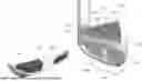
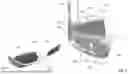
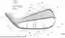
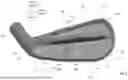
FIG. 1 is a partially exploded perspective view of a golf club head according to some examples.
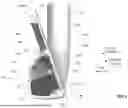
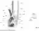
FIG. 2 is a back view of a front portion of the golf club head of FIG. 1.
FIG. 3 is a cross-sectional view of the golf club head of FIG. 1 along the line 3′-3′ in FIG. 2.
FIG. 4 is a cross-sectional view of the golf club head of FIG. 1 along the line 4′-4′ in FIG. 2.
FIG. 5 is a cross-sectional view of the golf club head of FIG. 1 along the line 5′-5′ in FIG. 2.
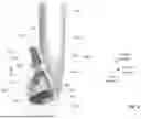
FIG. 6 is a back view of a front portion of another golf club head according to some examples.
DETAILED DESCRIPTION
Golf club heads, which may have a striking face with a variable thickness configured to improve certain golf club and ball flight characteristics, will now be described below in more detail with reference to the drawings.
FIG. 1 is a partially exploded perspective view of a golf club head 100 according to some examples. In the depicted example, the golf club head 100 is an iron type golf club head. FIG. 2 is a back view of a front portion 120 of the golf club head 100 of FIG. 1. FIG. 3 is a cross-sectional view of the golf club head 100 of FIG. 1 along the line 3′-3′ in FIG. 2. FIG. 4 is a cross-sectional view of the golf club head 100 of FIG. 1 along the line 4′-4′ in FIG. 2. FIG. 5 is a cross-sectional view of the golf club head 100 of FIG. 1 along the line 5′-5′ in FIG. 2.
Referring concurrently to FIGS. 1-5, the golf club head 100 includes a body 102 including a toe 103, a heel 104, a striking face 105 extending between the toe 103 and the heel 104 and having a lower leading edge 106 and an opposite upper topline edge 107, a sole 110 extending rearward from the lower leading edge 106 to a distal edge 111, a topline 112 extending rearward from the upper topline edge 107, a support bar 140 that protrudes rearwardly from the striking face 105 and generally extends along a toe-heel direction, and a back portion 113 coupled between the distal edge 111 of the sole 110 and the support bar 140 to form part of a cradle 119. As used herein, the toe-heel direction of the golf club head 100 includes both a toc-to-heel direction and a heel-to-toe direction of the golf club head 100. The striking face 105 may have a substantially flat frontal striking surface 105FS and an opposite rear surface 105R. One or more grooves 125 may be defined in the frontal striking surface 105FS of the striking face 105. The golf club head 100 may include a hosel 101 that is disposed at the heel 104 and that is configured to attach to a golf club shaft (not shown).
An elongated cavity 190 may be defined in the support bar 140 and may generally extend in the toc-heel direction. An elongated polymer 192 (e.g., a polymer strip) may be positioned at least partially (i.e., partially or entirely) in the cavity 190 and generally extend along the toe-heel direction. The polymer 192 can improve various performance properties of the golf club head 100, such as providing a more solid feel when striking a golf ball. In some other examples, the cavity 190 and polymer 192 are omitted. For example, the support bar 140 may be a solid, continuous piece of metal.
A rear portion of the body 102 may be defined by a cradle 119 that is attached (e.g., during the manufacturing of the golf club head 100) to a front portion 120 of the body 102. The cradle 119 may include at least part (i.e., part or all) of the sole 110 and at least part of the back portion 113. In some examples, the front portion 120 includes the striking face 105, the support bar 140, and at least part of the sole 110.
The golf club head 100 may have an upper cavity 123 and a lower cavity 121. The upper cavity 123 may be at least partially surrounded by the topline 112, an upper section 155 of the striking face 105, and the support bar 140. The upper cavity 123 may be exposed to the exterior of the golf club head 100 at a rear of the upper cavity 123. The lower cavity 121 may be at least partially surrounded by the support bar 140, a lower section 151 of the striking face 105, the sole 110, and the back portion 113. In some examples, the lower cavity 121 is entirely surrounded. For example, the lower cavity 121 may be fluidically sealed or fluidically separated from the exterior of the golf club head 100. The lower section 151 may be entirely below the support bar 140, and the upper section 155 may be entirely above the support bar 140.
Referring to FIGS. 2-5, the lower section 151 of the striking face 105 may include a heel portion 152 adjacent to the heel 102, a toe portion 154 adjacent to the toe 103, and a thick portion 153 between the heel portion 152 and the toe portion 154. In the depicted example, the lower section 151 also include an intermediate thin portion 156 that is both positioned between the heel portion 152 and the toe portion 154 and also positioned between the thick portion 153 and the support bar 140. In some examples, the rear surface 105R at the intermediate thin portion 156 is continuous and contiguous with the rear surface 105R at the heel and toe portions 152 and 154.
As explained in more detail below, a thickness of the lower section 151 may be configured (e.g., varied across the lower section 151) such that ball speed across the lower section 151 can be increased and made more uniform, golf ball launch angle can be increased, and flexure of the lower section 151 near the sole 110 and at the heel and toe portions 152 and 154 can be improved. This can lead to improved aerodynamic properties of the golf club head and improved performance of a person using the golf club head.
As used herein, thicknesses of the striking face 105 may be measured along a first direction that is perpendicular to the frontal striking surface 105FS and between the rear surface 105R of the striking face 105 and a frontal plane 105FP that is parallel and tangential to the frontal striking surface 105FS. In some examples, the frontal striking surface 105FS is an outer-most surface of the striking face 105 (ignoring any grooves in the striking face 105). A second direction is also referred to herein and may be defined to be parallel to the frontal striking surface 105FS and generally perpendicular to the toe-heel direction. For example, the second direction may be perpendicular to both the first direction and the toe-heel direction. In some other examples, the second direction may be defined to be perpendicular to a ground plane when the golf club head 100 is in the address position on the ground plane. The address position, as defined by the current application, sets up the golf club head 100 at an orientation that has a lie angle of 60 degrees similar to the requirements of the USGA. Once the lie angle is set at 60 degrees, the face angle of the golf club head is set to be square, which is defined as having a face angle of 0 degrees.
The thickness of the lower section 151 will be described in more detail below with reference to seven different positions on the lower section 151. These seven positions include first and second positions 161 and 162 on the toe portion 154, third and fourth positions 163 and 164 on the thick portion 153, fifth and sixth positions 165 and 166 on the heel portion 152, and a seventh position 167 on the intermediate thin position 156. The first, third, and fifth positions 161, 163, and 165 may have a same first height along the second direction from the lower leading edge 106 or from the ground plane, depending on how the second direction is defined. The second, fourth, and sixth positions 162, 164, and 166 may have a same second height along the second direction from the lower leading edge 106 or the ground plane, depending on how the second direction is defined. The seventh position 167 may have a third height along the second direction from the lower leading edge 106 or the ground plane, depending on how the second direction is defined. The second height may be greater than the first height, and the third height may be greater than the second height. For example, a difference between the first height and the second height may be any value within, or within any subrange within, 20% to 60% of a maximum height of the lower section 151 along the second direction. In some examples where the second direction is parallel to the frontal striking surface 105FS, the first and second positions 161 and 162 may be aligned along a line parallel to the second direction, the third, fourth, and seventh positions 163, 164, and 167 may be aligned along a line parallel to the second direction, and the fifth and sixth positions 165 and 166 may be aligned along a line parallel to the second direction.
The thick portion 153 may include a flat portion 153F and a tapered portion 153T at least partially surrounding the flat portion 153F. In the depicted example, the thick portion 153 and the flat portion 153F each extend from the sole 110 only part way (e.g., along the second direction) toward the support bar 140, and the tapered portion 153T has an upside down U-like shape that surrounds part of the flat portion 153F. By shaping and sizing the thick portion 153 to extend from the sole 110 only part way toward the support bar 140, a center of gravity (COG) can be controllably shifted downward compared to if the thick portion were to extend all the way up to the support bar 140. A greatest width of each of the thick portion 153 and the flat portion 153F along the toe-heel direction may be at least 5 mm.
The flat portion 153F may have substantially uniform thickness, for example, a thickness that deviates by less than 5%, 3%, 1%, or 0.5% across the flat portion 153F. For example, thicknesses at the third and fourth positions 163 and 164 may be substantially the same (e.g., within 5%, 3%, 1%, or 0.5% of each other). A thickness of the tapered portion 153T may decrease via a taper (e.g., a gradual taper) in a direction away from the flat portion 153F.
A thickness of the thick portion 153 (e.g., a thickness of the flat portion 153F) may be greater than each of a thickness of the heel portion 152 and a thickness of the toe portion 154. For example, the thick portion 153 may protrude further rearwardly compared to the heel and toe portions 152 and 154. A thickness at the third position 163 may be greater than each of a thickness at the first position 161 and a thickness at the fifth position 165. A thickness at the fourth position 164 may be greater than each of a thickness at the second position 162 and a thickness at the sixth position 166. In some examples, the thickness of the flat portion 153F may be greater than a thickness at any position across the heel and toe portions 152 and 154.
A thickness of the thick portion 153 (e.g., the thickness at the third position 163 or at the fourth position 164) may be greater than a thickness of the upper section 155 at any position across the upper section 155.
A thickness of the intermediate thin portion 156 may be less than a thickness of the thick portion 153 (e.g., a thickness of the flat portion 153F). For example, a thickness at the seventh position 167 may be less than each of the thickness at the third position 163 and the thickness at the fourth position 164. In some examples, the thickness at the seventh position 167 is greater than each of thicknesses at the first position 161, the second position 162, the fifth position 165, and the sixth position 166.
Each of the heel portion 152 and the toe portion 154 may have a tapered thickness, where the thickness is greater near the support bar 140 than it is near the sole 110. For example, thicknesses of the heel and toe portions 152 and 154 may gradually increase along a direction (e.g., along the second direction) from the sole 110 toward the support bar 140. In some examples, the thickness at the second position 162 at the second height is greater than the thickness at the first position 161 at the first height. The thickness at the sixth position 166 at the second height may be greater than the thickness at the fifth position 165 at the first height. In some examples, a difference between the thickness at the fourth position 164 and the thickness at the second position 162 is less than a difference between the thickness at the third position 163 and the thickness at the first position 161. A difference between the thickness at the fourth position 164 and the thickness at the sixth position 166 may be less than a difference between the thickness at the third position 163 and the thickness at the fifth position 165.
Each of the heel and toe portions 152 and 154 may taper at a rate such that a thickness at the top of the lower section 151 adjacent to the support bar 140 is 10% to 40% greater than a thickness at the bottom of the lower section 151 adjacent to the sole 110. In some examples, each of the heel and toe portions 152 and 154 tapers at a rate such that a greatest thickness is 10% to 40% greater than a smallest thickness.
By increasing a thickness of the lower section 151 at the thick portion 153 in a central region, and thinning out the lower sections of the heel and toe portions 152 and 154 near the sole 110, the stiffness of the lower section 151 can be increased in the central region and reduced in the heel and toe portions 152 and 154 near the sole 110. Accordingly, the flexure of the lower section 151 can be concentrated in the heel and toe portions 152 and 154 near the sole 110 without sacrificing the overall stiffness and structural integrity of the lower section 151. This configuration of the lower section 151 can increase ball speed at the heel and toe portions 152 and 154, improve uniformity of ball speed for golf shots taken across the lower section 151 along the toe-heel direction, and increase ball launch angle.
In some other examples, the thick portion 153 is provided and the thickness of each of the heel and toe portions 152 and 154 do not taper (e.g., the heel and toe portions 152 and 154 each have substantially uniform thickness). In such examples, the golf club head 100 can still exhibit the above-described performance improvements. For example, the thick portion 153 may be provided and the thickness of the heel and toe portions 152 and 154 may be uniformly thinned down so that the resulting heel and toe portions 152 and 154 each have uniform thickness. However, tapering the thickness of the heel and toe portions 152 and 154, as described herein, can increase the structural integrity and stiffness near the support bar 140, which can, among other things, concentrate flexure of the lower section 151 nearer to the sole 110. This can increase golf ball launch angle compared to when the heel and toe portions 152 and 154 are provided with uniform thicknesses.
The golf club head 100 may include a first weight 142 positioned within the lower cavity 121 and rearward to the heel portion 152. In some examples, the first weight 142 is entirely spaced apart from any line extending through the thick portion 153 along the first direction. The golf club head may include a second weight positioned within the lower cavity 121 and rearward to the toe portion 154. In some examples, the second weight 144 is entirely spaced apart from any line extending through the thick portion 153 along the first direction.
The first and second weights 142 and 143 may be attached (e.g., brazed, welded, adhered, etc.) to the cradle 110 and spaced apart from the rear surface 105R of the striking face 105. For example, each of the first and second weights 142 and 143 may directly contact at least one of an internal surface of the back portion 113 or an internal surface of the sole 110.
In some other examples, the first and second weights 142 and 143 are attached to the rear surface 105R of the striking face 105. However, this can increase stress at the brazed joint between the first and second weights 142 and 143 and the striking face 105, limit the flexure across the striking face 105, and limit the coefficient of restitution (COR) of the striking face 105. By instead attaching the first and second weights 142 and 143 to the cradle 119 and spacing them apart from the striking face 105, the flexure of the heel and toe portions 152 and 154 can be increased, and the COR of the lower section 151 can be increased.
In some examples, the thick portion 153 may protrude rearwardly compared to the heel portion 152 by a distance (as measured along the first direction) greater than a separation distance (as measured along the first direction) between the first weight 142 and the rear surface 105R of the heel portion 152. For example, the difference between the thickness at the third position 163 on the thick portion 153 and the thickness at the fifth position 165 on the heel portion 152 may be greater than a separation distance between a forward surface of the first weight 142 and the rear surface 105R of the heel portion 152, as measured along a line parallel to the first direction and extending through the fifth position 165. In some examples, a maximum difference between a thickness of the thick portion 153 and a thickness of the heel portion 152 is greater than a maximum separation distance between the first weight 142 and the rear surface 105R of the heel portion 152. In examples, a line drawn in a heel-to-toe direction tangential to a rearward-most point of the thick portion 153 (as measured along the first direction) intersects the first weight 142.
In some examples, the thick portion 153 may protrude rearwardly from the toe portion 154 by a distance (as measured along the first direction) greater than a separation distance (as measured along the first direction) between the second weight 143 and the rear surface 105R of the toe portion 154. For example, the difference between the thickness at the third position 163 on the thick portion 153 and the thickness at the first position 161 on the toc portion 154 may be greater than a separation distance between a forward surface of the second weight 143 and the rear surface 105R of the toe portion 154, as measured along a line parallel to the first direction and extending through the first position 161. In some examples, a maximum difference between a thickness of the thick portion 153 and a thickness of the toc portion 154 is greater than a maximum separation distance, as measured along the first direction, between the second weight 143 and the rear surface 105R of the toe portion 154. In examples, a line drawn in a heel-to-toe direction tangential to a rearward-most point of the thick portion 153 (as measured along the first direction) intersects the second weight 143.
FIG. 6 is a back view of a front portion 220 of another golf club head according to some examples. The golf club head of FIG. 6 may have some features similar to, or the same as, features of the golf club head 100 illustrated and described herein with reference to FIGS. 1-5. Therefore, redundant descriptions may not be repeated.
The lower section 121 of the striking face 105 may include the heel portion 152, the toe portion 154, and a thick portion 253 between the heel and toe portions 152 and 154. The thick portion 253 includes a flat portion 253F and a tapered portion 253T that at least partially surrounds the flat portion 253F. The thickness of the flat portion 253F is substantially uniform across the flat portion 253F, and the thickness of the tapered portion 253T decreases, via a taper, along a direction away from the flat portion 253F.
In the depicted example, the thick portion 253 and the flat portion 253F each has a quadrangular shape that extends from the sole 110 toward the support bar 140, and the tapered portion 253T has a generally upside down U-like shape that surrounds three generally flat sides of the flat portion 253F. In the depicted example, the thick portion 253 extends all the way to the support bar 140.
It will be understood that, although the terms “first”, “second”, “third”, etc., may be used herein to describe various elements, these elements should not be limited by these terms. These terms are only used to distinguish one element from another element. Thus, a first element discussed herein could be termed a second element, without departing from the spirit and scope of the present disclosure.
The terminology used herein is for the purpose of describing particular embodiments only and is not intended to be limiting of the present disclosure. It will be understood that the terms “comprises,” “comprising,” “includes,” “including,” and similar terms, when used in this specification, specify the presence of stated elements, but do not preclude the presence or addition of one or more other elements. Further, the use of “may” when describing embodiments of the present disclosure refers to “one or more embodiments of the present disclosure.”
It will be understood that when an element is referred to as being “on”, “connected to”, “coupled to”, or “adjacent to” another element, it can be directly on, connected to, coupled to, or adjacent to the other element, or one or more intervening element(s) may be present. In contrast, when an element or layer is referred to as being “directly on,” “directly connected to”, “directly coupled to”, or “immediately adjacent to” another element, there are no intervening elements present. Similar terms and phrases should be understood in a similar manner to encompass both direct and indirect affiliations between two or more elements being discussed.
Also, any numerical range recited herein is intended to include all sub-ranges of the same numerical precision subsumed within the recited range. For example, a range of “1.0 to 10.0” is intended to include all subranges between (and including) the recited minimum value of 1.0 and the recited maximum value of 10.0, that is, having a minimum value equal to or greater than 1.0 and a maximum value equal to or less than 10.0, such as, for example, 2.4 to 7.6. Any maximum numerical limitation recited herein is intended to include all lower numerical limitations subsumed therein and any minimum numerical limitation recited in this specification is intended to include all higher numerical limitations subsumed therein. Accordingly, Applicant reserves the right to amend this specification, including the claims, to expressly recite any sub-range subsumed within the ranges expressly recited herein.
Although specific embodiments are described herein, the scope of the technology is not limited to those specific embodiments. Moreover, while different examples and embodiments may be described separately, such embodiments and examples may be combined with one another in implementing the technology described herein. One skilled in the art will recognize other embodiments or improvements that are within the scope and spirit of the present technology. Therefore, the specific embodiments described herein are only provided as illustrative embodiments. The scope of the technology is defined by the following claims and any equivalents therein.
Claims
What is claimed is:1. An iron type golf club head, comprising:
a striking face having a substantially flat frontal striking surface, and having a lower leading edge and an opposite upper topline edge;
a topline extending rearward from the upper topline edge;
a sole extending rearward from the lower leading edge;
a support bar protruding rearwardly from the striking face and extending in a toe-heel direction of the golf club head;
an upper cavity at least partially surrounded by the topline, an upper section of the striking face, and the support bar; and
a lower cavity at least partially surrounded by the support bar, a lower section of the striking face, and the sole,
wherein the lower section of the striking face comprises a heel portion, a toe portion, and a thick portion between the heel portion and the toe portion, and
wherein a first thickness of the thick portion is greater than each of a second thickness of the heel portion and a third thickness of the toe portion.
2. The golf club head of claim 1, wherein the lower cavity is entirely enclosed by the golf club head, and
wherein the upper cavity is exposed, at a rear of the upper cavity, to the exterior of the golf club head.
3. The golf club head of claim 1, wherein the first thickness is greater than a thickness of the upper section of the striking face at any position on the upper section of the striking face.
4. The golf club head of claim 1, wherein the thick portion comprises:
a flat portion having a substantially uniform thickness; and
a tapered edge at least partially surrounding the flat portion and having a tapered thickness.
5. The golf club head of claim 1, wherein the first thickness is greater than a thickness of the lower section of the striking face at any position over the heel portion and the toe portion.
6. The golf club head of claim 1, wherein the thick portion has a shape extending from the sole toward the support bar.
7. The golf club head of claim 6, wherein the shape of the thick portion extends to the support bar.
8. The golf club head of claim 6, wherein the shape of the thick portion extends only part way to the support bar, and
wherein a greatest thickness of the thick portion is greater than a greatest thickness of a portion of the lower section of the striking face between the thick portion and the support bar.
9. The golf club head of claim 1, wherein the second thickness is measured on the heel portion at a first height from the lower leading edge along a first direction parallel to the frontal striking surface and perpendicular to the toe-heel direction, and
wherein a fourth thickness on the heel portion, at a second height from the lower leading edge along the first direction, is greater than the second thickness, the second height being greater than the first height.
10. The golf club head of claim 1, comprising:
a cradle defining a rear portion of a body of the golf club head and being attached to a front portion of the body, the cradle comprising at least part of the sole and at least part of a back portion coupled between the sole and the support bar;
a first weight attached to the cradle and positioned in the lower cavity rearward to, and spaced apart from, the heel portion of the striking face; and
a second weight attached to the cradle and positioned in the lower cavity rearward to, and spaced apart from, the toe portion of the striking face.
11. An iron type golf club head, comprising:
a striking face having a substantially flat frontal striking surface, and having a lower leading edge and an opposite upper topline edge;
a sole extending rearward from the lower leading edge; and
a support bar protruding rearwardly from the striking face,
wherein the striking face comprises an upper section above the support bar and a lower section below the support bar,
wherein the lower section of the striking face comprises a heel portion, a toe portion, and a thick portion between the heel portion and the toe portion,
wherein a first thickness of the thick portion, as measured at a first height from the lower leading edge, is greater than a second thickness of the heel portion, as measured at the first height from the lower leading edge, and
wherein the second thickness of the heel portion is less than a third thickness of the heel portion, as measured at a second height from the lower leading edge, the second height being greater than the first height.
12. The golf club head of claim 11, comprising:
a topline extending rearwardly from the upper topline edge of the striking face;
a back portion coupled between the sole and the support bar;
an upper cavity partially surrounded by the topline, the upper section of the striking face, and the support bar, and being exposed to the exterior of the golf club head at a rear of the upper cavity; and
a lower cavity at least partially surrounded by the support bar, the lower section of the striking face, the back portion, and the sole.
13. The golf club head of claim 12, further comprising:
a first weight attached to the back portion and positioned in the lower cavity rearward to the heel portion; and
a second weight attached to the back portion and positioned in the lower cavity rearward to the toe portion
14. The golf club head of claim 11, wherein the first thickness of the thick portion is substantially equal to a fourth thickness of the thick portion, as measured at the second height from the lower leading edge.
15. The golf club head of claim 11, wherein a thickness of the heel portion gradually increases from the lower leading edge toward the support bar, and
wherein a thickness of the toe portion gradually increases from the lower leading edge toward the support bar.
16. An iron type golf club head, comprising:
a striking face having a substantially flat frontal striking surface, and having a lower leading edge and an opposite upper topline edge;
a cradle defining a rear portion of a body of the golf club head and attached to a front portion of the body, the cradle comprising:
at least part of a sole extending rearward from the lower leading edge to a distal edge, and
at least part of a back portion extending from the distal edge of the sole,
wherein a lower cavity of the golf club head is at least partially surrounded by a lower section of the striking face, the sole, and the back portion; and
a first weight in the lower cavity,
wherein the lower section of the striking face comprises a heel portion, a toe portion, and a thick portion between the heel portion and the toe portion,
wherein a first thickness of the thick portion is greater than each of a second thickness of the heel portion and a third thickness of the toe portion,
wherein the first weight is attached to the cradle and positioned in the lower cavity rearward to the heel portion, and
wherein a difference between the first thickness and the second thickness is greater than or equal to a separation distance between the first weight and the heel portion.
17. The golf club head of claim 16, comprising:
a topline extending rearwardly from the upper topline edge of the striking face;
a support bar protruding rearwardly from the striking face and extending in a toe-heel direction of the golf club head; and
an upper cavity partially surrounded by the topline, an upper section of the striking face, and the support bar, and being exposed to the exterior of the golf club head at a rear of the upper cavity,
wherein the lower cavity is at least partially surrounded by the support bar.
18. The golf club head of claim 17, wherein the first thickness is greater than the thickness of the upper section at any position on the upper section.
19. The golf club head of claim 16, comprising a second weight attached to the cradle and positioned in the lower cavity rearward to, and spaced apart from, the toe portion.
20. The golf club head of claim 16, wherein the thick portion comprises a flat portion having a substantially uniform thickness.
Images & Drawings included:
Sources:
- United States Patent and Trademark Office - verify current appl. status at the USPTO↗
Similar patent applications:
- » 20110312438
Golf club head with variable face thickness - » 20120021849
Golf club head with variable face thickness - » 20060079347
Golf club head with variable face thickness - » 20070004536
Golf club head with variable face thickness - » 20070287553
Golf club head with variable face thickness - » 20060079345
Golf club head with variable face thickness - » 20080051217
Golf club head with variable face thickness - » 20090069112
Golf club head with variable face thickness - » 20100178997
Golf club head with variable face thickness - » 20140213388
Golf club head with variable face thickness
Recent applications in this class:
- » 20250352869 2025-11-20
GOLF CLUB HEADS HAVING CONSISTENT PERFORMANCE - » 20250332490 2025-10-30
GOLF CLUB HEAD WITH LOW HOSEL BORE - » 20250319368 2025-10-16
GOLF CLUB HEAD WITH INSERT - » 20250319367 2025-10-16
IRON-TYPE GOLF CLUB HEAD - » 20250256172 2025-08-14
GOLF CLUB HEAD INCLUDING A REMOVABLE WEIGHT - » 20250256171 2025-08-14
GOLF CLUB HEAD INCLUDING A REMOVABLE WEIGHT - » 20250222322 2025-07-10
GOLF CLUB HEAD - » 20250222321 2025-07-10
GOLF CLUB - » 20250222320 2025-07-10
GOLF CLUB HEAD - » 20250213936 2025-07-03
GOLF CLUB HEAD