Predicting Frackable Intervals
US20250354485A1
2025-11-20
18/666,142
2024-05-16
Smart Summary: A new method helps predict where it's possible to successfully fracture rock for oil and gas extraction. It starts by gathering information about the rock's structure from well logs. This information is combined with data from drilling and past performance to create a detailed dataset. A machine learning model is then trained using this dataset to estimate the chances of success for different rock intervals. This approach aims to improve the efficiency of finding suitable areas for fracking. 🚀 TL;DR
Abstract:
A computer implemented method that enables predicting frackable intervals. The method includes extracting rock fabric data from well logs and integrating rock fabric data with well drilling data and corresponding historical performance data to create labeled rock fabric data. The method also includes training a machine learning model to predict a probability of being a successful fracture for at least one interval using the labeled rock fabric data.
Inventors:
- Ahmad Azly Bin Abdul Aziz 4 🇸🇦 Dhahran, Saudi Arabia
- Ferney Geovany Moreno Sierra 3 🇨🇴 Bogota, Colombia
- Abdullah Mohammed A. Alshammasi 1 🇸🇦 Qatif, Saudi Arabia
Applicant:
Interested in similar patents?
Get notified when new applications in this technology area are published.
Classification:
E21B49/003 » CPC main
Testing the nature of borehole walls; Formation testing; Methods or apparatus for obtaining samples of soil or well fluids, specially adapted to earth drilling or wells by analysing drilling variables or conditions
E21B43/26 » CPC further
Methods or apparatus for obtaining oil, gas, water, soluble or meltable materials or a slurry of minerals from wells; Methods for stimulating production by forming crevices or fractures
E21B2200/22 » CPC further
Special features related to earth drilling for obtaining oil, gas or water Fuzzy logic, artificial intelligence, neural networks or the like
E21B49/00 IPC
Testing the nature of borehole walls; Formation testing; Methods or apparatus for obtaining samples of soil or well fluids, specially adapted to earth drilling or wells
Description
TECHNICAL FIELD
This disclosure relates generally to predicting frackable intervals.
BACKGROUND
Well stimulation refers to interventions performed on wells to increase production by improving the flow of hydrocarbons from the reservoir into the wellbore. Fracking is a well stimulation technique where formations are fractured by a pressurized liquid. During fracking, a fluid is injected under high-pressure into a wellbore to create cracks in the subsurface through which hydrocarbons, water, and brine flow more freely.
BRIEF DESCRIPTION OF DRAWINGS
FIG. 1 shows a workflow for predicting frackable intervals.
FIG. 2 shows cross plots of variables 1-4.
FIG. 3 shows cross plots of variables 5-8.
FIG. 4 shows variable importances.
FIG. 5 shows the cumulative importances of variables selected for training or testing the machine learning model.
FIG. 6 shows the identification of fracking locations at various intervals of a well.
FIG. 7 shows model results.
FIG. 8 is a process flow diagram of a process that enables predicting frackable intervals.
FIG. 9 illustrates hydrocarbon production operations that include both one or more field operations and one or more computational operations, which exchange information and control exploration for the production of hydrocarbons.
FIG. 10 is a schematic illustration of an example controller (or control system) for that enables predicting frackable intervals.
DETAILED DESCRIPTION
Well stimulation is performed to increase the flow of oil and gas from drilled wells. In examples, well stimulation efforts, such as fracking, are applied in unconventional wells, tight wells, and conventional wells to increase hydrocarbon recovery. For example, fracturing is used in unconventional wells along with horizontal drilling for increased production. Fracturing is used in conventional wells, for example, to stimulate production.
In examples, a tight well is a well with low permeability. Tight wells are stimulated to enhance productivity near the wellbore region to obtain commercial and sustainable production from the formation. Stimulations at tight wells are achieved using a stimulation treatment by which a reactive or non-reactive fluid is injected into a reservoir at a pressure above a minimum in-situ stress to create a highly permeable path (e.g., fracture) in the formation to bypass near wellbore damage induced by drilling operations. The fracture extends deep into the formation to enable the flow of hydrocarbons. Creating fractures in formations is known as hydraulic fracturing or fracking, in which the rock formation is fractured by a hydraulically pressurized fluid made of water, sand, proppants, chemicals, or any combinations thereof.
Embodiments described herein predict frackable intervals. Frackable refers to being suitable for hydraulic fracturing, or fracking. Rock fabric data from well logs is integrated with well drilling data and corresponding historical performance data to create labeled rock fabric data. A machine learning model is trained to predict a probability of a successful fracture for at least one interval using the labeled rock fabric data. In some embodiments, an integrated multi-disciplinary engineering design process is implemented to achieve an effective fracture geometry. For example, a stimulation design generated as described herein incorporates the well history, location, rock, and fluid properties. Traditionally, a human selects intervals where fracture will be initiated and subsequently performs the stimulation job using manual processes. Even though manual processes are in place to select intervals to initiate fracture, historical performance shows on average 40% of the perforated intervals using traditional manual processes are unable to frack the rock causing the cancellation of stimulation stages. Consequently, stimulation operations are not efficient and incur unnecessary costs in unknowingly attending to unfrackable intervals determined using manual processes.
Some advantages of the present techniques include an improvement to the identification of fracking intervals by leveraging rock fabric properties and historical data. Traditional techniques are limited to mapping frackability using seismic data, predicting geomechanical properties, predicting rock properties measured in the lab, or predicting fracture geometry based on real-time data. By contrast, the present techniques decouple geomechanics from the prediction and apply rock fabric data to discover frackable intervals along with leveraging existing well data. In this manner, the present techniques operate without geomechanical input for prediction, such as geomechanical input derived from petrophysical data. The present techniques use rock fabric data to avoid uncertainty on geomechanics parameter predictions. Traditional techniques suffer from the inability to robustly predict frackable intervals in tight wells or unconventional wells where parameters of the well data fails to indicate that an interval is not frackable. Traditional techniques use detailed core analysis and calibration test to generate reliable predictions.
The present techniques use rock fabric data from well logs that are integrated with the historical frack jobs. The rock fabric data is then processed using advanced data analytics and machine learning to predict the frackable intervals. The present techniques save time and resources by avoiding attempts to stimulate unfrackable intervals. Accordingly, in some embodiments the present techniques robustly detect unfrackable intervals.
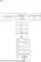
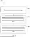
FIG. 1 shows a workflow 100 for predicting frackable intervals. As shown in the example of FIG. 1, historical fracking jobs 102, rock fabric data 104, and well drilling data 106. In examples, historical fracking jobs includes 102 historical hydraulic fracturing performance. In examples, rock fabric data is obtained from well logs, including but not limited to, formation bulk density, sonic, gamma ray, resistivity, wellbore caliper, neutron porosity, total porosity, effective porosity, and volume of quartz. One or any combination of well logs is integrated with the historical frack jobs. In examples, the well drilling data 106 is captured from a predefined time period, such as the past 10 years. Well drilling data describes how the well is completed, such as a vertical well or horizontal well. Well drilling data also describes the mud weight used across reservoir interval, completion tubing strength, and other well completion data including but not limited to well head data, borehole diameters, casing size, casing lengths, and casing materials. In examples, the well drilling data 106 used for predictions are the well drilling data that statistically influences the resulting prediction. In examples, the historical fracking jobs 102, rock fabric data 104, and well drilling data 106 are compiled into a single database. In examples, the historical fracking jobs 102, rock fabric data 104, and well drilling data 106 are standardized and stored in the database. Data standardization converts the historical fracking jobs 102, rock fabric data 104, and well drilling data 106 into a standard format for input into a machine learning model. In examples, the historical fracking jobs 102, rock fabric data 104, and well drilling data 106 are obtained from various organizations and service providers. Data standardization ensures that data from various organizations and service providers are in a predetermined format used for input to a machine learning model. For example, data standardization includes converting measurements into the metric system or converting dates into a single format.
Data preparation 108 identifies patterns or clusters of wellbore intervals where frackability issues were encountered using advanced data analytics applied to the historical fracking jobs 102, rock fabric data 104, and well drilling data 106. In some embodiments, input data is quality checked by subject matter experts. In examples, quality checking the data includes, but is not limited to: 1) ensuring that perforation intervals are reported at a correct depth; 2) reconciling formation tops using palynology, coring, and well based and structural field correlations; 3) applying environmental correction and noise reduction to petrophysical data; 4) validating data from stimulation and perforation using post job reports and daily operations; and any combinations thereof.
The prepared data is merged into a single data-frame that is a function of well number, perforation depth, and operational time. The data-frame has more than 119 input parameters for each perforation interval from different disciplines (e.g., drilling, services organizations, stimulation data, subject matter experts, and reservoir management) as captured in the historical fracking jobs 102, rock fabric data 104, and well drilling data 106.
During data preparation 108, data analytics is performed, where patterns and/clusters of intervals with frackability issues are identified. Geomechanics is decoupled from the workflow 100, and instead the relationship between frackability and the rock fabric properties such as porosity, permeability, resistivity, mineralogy, etc. is used to predict frackable intervals. The data analytics includes assessing the input parameters against the discretized historical frackability results, where a value of 0 indicates not frackable and a value of 1 indicates frackable. Exploratory data analysis describes data statistically to identify patterns that are used in predicting frackable intervals. The statistically insignificant variables are removed from consideration, reducing the relevant variables from 119 to 13. In some embodiments, statistical significance is determined according to a predetermined threshold, such as 5%. The significance level describes a likelihood of the variable influencing the predicted frackable intervals. In some embodiments, trained machine learning models, such as decision trees, that output the relevant contribution of each variable on the prediction of frackable intervals. An optimization or parameter reduction is performed to reach maximum accuracy of the predicted frackable intervals with minimum input properties to build parsimonious and robust models that predict frackable intervals.
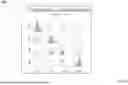
FIG. 2 shows a cross plot of variables 1-4. FIG. 3 shows a cross plot of variables 5-8. FIGS. 2 and 3 show data clustering where frackability issues were encountered. Identified clusters with frackability issues are enclosed in dashed polygons on each respective cross plot.
After the most relevant variables were selected, the data-frame was divided into two data sets randomly keeping same proportion of frackable and non-frackable intervals, one set for training and another for testing. Data modeling using machine learning 110 trains a machine learning model to predict the frackability of at least one interval. Multiple machine learning algorithms were evaluated to assess the predictability and accuracy of the respective model, among them binary classification, linear logistic regression, support vector model, anomaly detection, neural network and random forest.
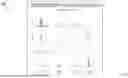
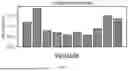
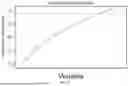
During the modeling stage, the importance (e.g., statistical significance) of each variable in prediction model is estimated. FIG. 4 shows variable importances. In the example of FIG. 4, each bar corresponds to a final input variable used in the model after the variable reduction workflow. The y-axis of FIG. 4 refers to the importance contribution to the total prediction in fraction. The sum of the respective importances for each variable is equal to 1. Once the model is selected and tuned, the model is tested against the testing data set. The model outputs discretized intervals with high probability of being successfully frac. In examples, variables are selected for training the machine learning model with a cumulative importance that satisfy a predetermined threshold. FIG. 5 shows the cumulative importances of variables selected for training or testing the machine learning model.
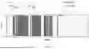
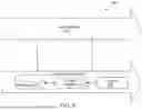
FIG. 6 shows the identification of fracking location at various intervals of a well. In particular, fracking flags 602, 604, and 606 are shown at various intervals. Fracking flags 602 and 604 indicate that the corresponding interval is suitable for fracking. Fracking flag 606 indicates that the corresponding interval is not suitable for fracking. In examples, the present techniques yield a +95% accuracy in predicting frackable and unfrackable intervals. In examples, the validated model is executed for blind testing with additional intervals that were not included in the initial analysis. The model predicted frackable and un-frackable with the same accuracy as observed during the training and testing stages (+95%).
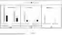
FIG. 7 shows model results during a training test at reference number 702, during a blind test at reference number 704, and during deployment at reference number 706. In the example of FIG. 7, the cluster number is defined as the number of perforations where stimulation was attempted. Additionally, the number of wells is defined as total well count included for a respective scenario (e.g., training test, blind test, or deployment). “Frac” refers to the interval count without frackability issues. “No Frac” refers to the interval count with frackability issues. In some embodiments, the trained model to predict frackable intervals has a greater than 95% successful prediction rate for frackable and unfrackable clusters. This is shown in the deployment at reference number 706 where there are no unfrackable clusters the trained machine learning model was deployed.
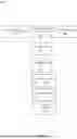
In an example the data driven solution workflow 100 of FIG. 1 was deployed in the field on data obtained from newly drilled wells with accurate output. Table 1 is an example of predictions made for wells of a formation. As shown by Table 1, the perforated intervals selected using the workflow were successfully fracked and therefore provided significant cost saving and efficient operations. The workflow 100 of FIG. 1 was also implemented in different gas fields with good results as shown in Table 1.
| TABLE 1 | |||||
| Frackability | |||||
| Well | Top | Probability | Prediction | Prediction (0/1) | Actual (0/1) |
| Field_2_well_1 | interval_1 | 0.93 | Frackable | 1 | 1 |
| Field_2_well_1 | interval_2 | 0.58 | Frackable | 1 | 1 |
| Field_2_well_1 | interval_3 | 0.64 | Frackable | 1 | 1 |
| Field_2_well_1 | interval_4 | 0.86 | Frackable | 1 | 1 |
| Field_2_well_1 | interval_5 | 0.86 | Frackable | 1 | 1 |
| Field_2_well_2 | interval_1 | 0.49 | Not Frackable | 0 | NA |
| Field_2_well_2 | interval_2 | 1 | Frackable | 1 | 1 |
| Field_2_well_2 | interval_3 | 1 | Frackable | 1 | 1 |
| Field_2_well_2 | interval_4 | 1 | Frackable | 1 | 1 |
| Field_2_well_2 | interval_5 | 1 | Frackable | 1 | 1 |
| Field_2_well_2 | interval_6 | 1 | Frackable | 1 | 1 |
| Field_2_well_3 | interval_1 | 0.14 | Not Frackable | 0 | 1 |
| Field_2_well_3 | interval_2 | 0.2 | Not Frackable | 0 | 1 |
| Field_2_well_3 | interval_3 | 0.95 | Frackable | 1 | 1 |
| Field_2_well_3 | interval_4 | 0.81 | Frackable | 1 | 1 |
| Field_2_well_3 | interval_5 | 0.86 | Frackable | 1 | 1 |
| Field_2_well_3 | interval_6 | 0.99 | Frackable | 1 | 1 |
| Field_2_well_3 | interval_7 | 0.93 | Frackable | 1 | 1 |
| Field_2_well_4 | interval_1 | 1 | Frackable | 1 | NA |
| Field_2_well_5 | interval_1 | 0.049 | Not Frackable | 0 | 0 |
| Field_2_well_5 | interval_2 | 0 | Not Frackable | 0 | 0 |
| Field_2_well_5 | interval_3 | 0 | Not Frackable | 0 | 0 |
| Field_2_well_6 | interval_1 | 1 | Frackable | 1 | 1 |
| Field_2_well_6 | interval_2 | 1 | Frackable | 1 | 1 |
| Field_2_well_6 | interval_3 | 1 | Frackable | 1 | 1 |
| Field_2_well_6 | interval_4 | 0.76 | Frackable | 1 | 1 |
| Field_2_well_6 | interval_5 | 0.93 | Frackable | 1 | 1 |
| Field_2_well_6 | interval_6 | 0.96 | Frackable | 1 | 1 |
FIG. 8 is a process flow diagram of a process 400 that enables predicting frackable intervals.
At block 802 rock fabric data is extracted from well logs. In some embodiments, well log data comprising parameters is assessed for each perforation interval from different disciplines against the discretized historical frackability results to minimize parameters integrated with historical performance data (or to select the most relevant parameters).
At block 804, rock fabric data from well logs is integrated with well drilling data and corresponding historical performance data (e.g., data preparation) to create labeled rock fabric data. In some embodiments, patterns or clusters of intervals where frackability issues were encountered are identified. Labeled rock fabric data is created by assessing well log variables/parameters for each perforation interval from different disciplines and labeling respective variables/parameters as frackable or unfrackable. In some embodiments, the machine learning model is trained to predict a probability of being an unsuccessful frac for discretized intervals.
At block 806, a machine learning model is trained (e.g., data modeling) to predict a probability of being a successful fracture for at least one interval using the labeled rock fabric data. In some embodiments, a stimulation operation is automatically executed in an interval when a probability of being a successful frac satisfies a predetermined threshold. In some embodiments, the stimulation operation automatically bypasses intervals when a probability of being an unsuccessful frac satisfies a predetermined threshold. In some embodiments, new, unseen well log data is input to the trained machine learning model to predict a probability of being a successful frac for discretized intervals.
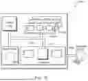
FIG. 9 illustrates hydrocarbon production operations 900 that include both one or more field operations 910 and one or more computational operations 912, which exchange information and control exploration for the production of hydrocarbons. In some implementations, outputs of techniques of the present disclosure can be performed before, during, or in combination with the hydrocarbon production operations 900, specifically, for example, either as field operations 910 or computational operations 912, or both.
Examples of field operations 910 include forming/drilling a wellbore, hydraulic fracturing, producing through the wellbore, injecting fluids (such as water) through the wellbore, to name a few. In some implementations, methods of the present disclosure can trigger or control the field operations 910. For example, the methods of the present disclosure can generate data from hardware/software including sensors and physical data gathering equipment (e.g., seismic sensors, well logging tools, flow meters, and temperature and pressure sensors). The methods of the present disclosure can include transmitting the data from the hardware/software to the field operations 910 and responsively triggering the field operations 910 including, for example, generating plans and signals that provide feedback to and control physical components of the field operations 910. Alternatively or in addition, the field operations 910 can trigger the methods of the present disclosure. For example, implementing physical components (including, for example, hardware, such as sensors) deployed in the field operations 910 can generate plans and signals that can be provided as input or feedback (or both) to the methods of the present disclosure.
Examples of computational operations 912 include one or more computer systems 920 that include one or more processors and computer-readable media (e.g., non-transitory computer-readable media) operatively coupled to the one or more processors to execute computer operations to perform the methods of the present disclosure. The computational operations 912 can be implemented using one or more databases 918, which store data received from the field operations 910 and/or generated internally within the computational operations 912 (e.g., by implementing the methods of the present disclosure) or both. For example, the one or more computer systems 920 process inputs from the field operations 910 to assess conditions in the physical world, the outputs of which are stored in the databases 918. For example, seismic sensors of the field operations 910 can be used to perform a seismic survey to map subterranean features, such as facies and faults. In performing a seismic survey, seismic sources (e.g., seismic vibrators or explosions) generate seismic waves that propagate in the earth and seismic receivers (e.g., geophones) measure reflections generated as the seismic waves interact with boundaries between layers of a subsurface formation. The source and received signals are provided to the computational operations 912 where they are stored in the databases 918 and analyzed by the one or more computer systems 920.
In some implementations, one or more outputs 922 generated by the one or more computer systems 920 can be provided as feedback/input to the field operations 910 (either as direct input or stored in the databases 918). The field operations 910 can use the feedback/input to control physical components used to perform the field operations 910 in the real world.
For example, the computational operations 912 can process the seismic data to generate three-dimensional (3D) maps of the subsurface formation. The computational operations 912 can use these 3D maps to provide plans for locating and drilling exploratory wells. In some operations, the exploratory wells are drilled using logging-while-drilling (LWD) techniques which incorporate logging tools into the drill string. LWD techniques can enable the computational operations 912 to process new information about the formation and control the drilling to adjust to the observed conditions in real-time.
The one or more computer systems 920 can update the 3D maps of the subsurface formation as information from one exploration well is received and the computational operations 912 can adjust the location of the next exploration well based on the updated 3D maps. Similarly, the data received from production operations can be used by the computational operations 912 to control components of the production operations. For example, production well and pipeline data can be analyzed to predict slugging in pipelines leading to a refinery and the computational operations 912 can control machine operated valves upstream of the refinery to reduce the likelihood of plant disruptions that run the risk of taking the plant offline.
In some implementations of the computational operations 912, customized user interfaces can present intermediate or final results of the above-described processes to a user. Information can be presented in one or more textual, tabular, or graphical formats, such as through a dashboard. The information can be presented at one or more on-site locations (such as at an oil well or other facility), on the Internet (such as on a webpage), on a mobile application (or app), or at a central processing facility.
The presented information can include feedback, such as changes in parameters or processing inputs, that the user can select to improve a production environment, such as in the exploration, production, and/or testing of petrochemical processes or facilities. For example, the feedback can include parameters that, when selected by the user, can cause a change to, or an improvement in, drilling parameters (including drill bit speed and direction) or overall production of a gas or oil well. The feedback, when implemented by the user, can improve the speed and accuracy of calculations, streamline processes, improve models, and solve problems related to efficiency, performance, safety, reliability, costs, downtime, and the need for human interaction.
In some implementations, the feedback can be implemented in real-time, such as to provide an immediate or near-immediate change in operations or in a model. The term real-time (or similar terms as understood by one of ordinary skill in the art) means that an action and a response are temporally proximate such that an individual perceives the action and the response occurring substantially simultaneously. For example, the time difference for a response to display (or for an initiation of a display) of data following the individual's action to access the data can be less than 1 millisecond (ms), less than 1 second(s), or less than 5 s. While the requested data need not be displayed (or initiated for display) instantaneously, it is displayed (or initiated for display) without any intentional delay, taking into account processing limitations of a described computing system and time required to, for example, gather, accurately measure, analyze, process, store, or transmit the data.
Events can include readings or measurements captured by downhole equipment such as sensors, pumps, bottom hole assemblies, or other equipment. The readings or measurements can be analyzed at the surface, such as by using applications that can include modeling applications and machine learning. The analysis can be used to generate changes to settings of downhole equipment, such as drilling equipment. In some implementations, values of parameters or other variables that are determined can be used automatically (such as through using rules) to implement changes in oil or gas well exploration, production/drilling, or testing. For example, outputs of the present disclosure can be used as inputs to other equipment and/or systems at a facility. This can be especially useful for systems or various pieces of equipment that are located several meters or several miles apart, or are located in different countries or other jurisdictions.
FIG. 10 is a schematic illustration of an example controller 1000 (or control system) for that enables predicting frackable intervals. For example, the controller 1000 may be operable according to the workflow 100 of FIG. 1 or the process 800 of FIG. 8. In some embodiments, the controller 1000 is the same as or similar to the computer systems 920 of FIG. 9. The controller 1000 is intended to include various forms of digital computers, such as printed circuit boards (PCB), processors, digital circuitry, or otherwise parts of a system for supply chain alert management. Additionally the system can include portable storage media, such as, Universal Serial Bus (USB) flash drives. For example, the USB flash drives may store operating systems and other applications. The USB flash drives can include input/output components, such as a wireless transmitter or USB connector that may be inserted into a USB port of another computing device.
The controller 1000 includes a processor 1010, a memory 1020, a storage device 1030, and an input/output interface 1040 communicatively coupled with input/output devices 1060 (for example, displays, keyboards, measurement devices, sensors, valves, pumps). Each of the components 1010, 1020, 1030, and 1040 are interconnected using a system bus 1050. The processor 1010 is capable of processing instructions for execution within the controller 1000. The processor may be designed using any of a number of architectures. For example, the processor 1010 may be a CISC (Complex Instruction Set Computers) processor, a RISC (Reduced Instruction Set Computer) processor, or a MISC (Minimal Instruction Set Computer) processor.
In one implementation, the processor 1010 is a single-threaded processor. In another implementation, the processor 1010 is a multi-threaded processor. The processor 1010 is capable of processing instructions stored in the memory 1020 or on the storage device 1030 to display graphical information for a user interface on the input/output interface 1040.
The memory 1020 stores information within the controller 1000. In one implementation, the memory 1020 is a computer-readable medium. In one implementation, the memory 1020 is a volatile memory unit. In another implementation, the memory 1020 is a nonvolatile memory unit.
The storage device 1030 is capable of providing mass storage for the controller 1000. In one implementation, the storage device 1030 is a computer-readable medium. In various different implementations, the storage device 1030 may be a floppy disk device, a hard disk device, an optical disk device, or a tape device.
The input/output interface 1040 provides input/output operations for the controller 1000. In one implementation, the input/output devices 1060 includes a keyboard and/or pointing device. In another implementation, the input/output devices 1060 includes a display unit for displaying graphical user interfaces.
There can be any number of controllers 1000 associated with, or external to, a computer system containing controller 1000, with each controller 1000 communicating over a network. Further, the terms “client,” “user,” and other appropriate terminology can be used interchangeably, as appropriate, without departing from the scope of the present disclosure. Moreover, the present disclosure contemplates that many users can use one controller 1000 and one user can use multiple controllers 1000.
Embodiments/Examples
According to some non-limiting embodiments or examples, provided is a computer-implemented method of training a neural network for predicting frackable intervals including: extracting, using at least one hardware processor, rock fabric data from well logs; integrating, using the at least one hardware processor, rock fabric data from well logs with well drilling data and corresponding historical performance data to create labeled rock fabric data; and training, using the at least one hardware processor, a machine learning model to predict a probability of being a successful fracture for at least one interval using the labeled rock fabric data.
According to some non-limiting embodiments or examples, provided is an apparatus including a non-transitory, computer readable, storage medium that stores instructions that, when executed by at least one processor, cause the at least one processor to perform operations including: extracting rock fabric data from well logs; integrating rock fabric data from well logs with well drilling data and corresponding historical performance data to create labeled rock fabric data; and training a machine learning model to predict a probability of being a successful fracture for at least one interval using the labeled rock fabric data.
According to some non-limiting embodiments or examples, provided is a system, including: one or more memory modules; one or more hardware processors communicably coupled to the one or more memory modules, the one or more hardware processors configured to execute instructions stored on the one or more memory modules to perform operations including: extracting rock fabric data from well logs; integrating rock fabric data from well logs with well drilling data and corresponding historical performance data to create labeled rock fabric data; and training a machine learning model to predict a probability of being a successful fracture for at least one interval using the labeled rock fabric data.
Further non-limiting aspects or embodiments are set forth in the following numbered embodiments:
Embodiment 1: A computer-implemented method of training a neural network for predicting frackable intervals including: extracting, using at least one hardware processor, rock fabric data from well logs; integrating, using the at least one hardware processor, rock fabric data from well logs with well drilling data and corresponding historical performance data to create labeled rock fabric data; and training, using the at least one hardware processor, a machine learning model to predict a probability of being a successful fracture for at least one interval using the labeled rock fabric data.
Embodiment 2: The computer implemented method of any preceding embodiment, including identifying patterns or clusters of intervals where frackability issues were encountered, and training the machine learning model using data corresponding to the clusters.
Embodiment 3: The computer implemented method of any preceding embodiment, wherein labeled rock fabric data is created by assessing well log parameters for each perforation interval from different disciplines and labeling respective parameters as frackable or unfrackable.
Embodiment 4: The computer implemented method of any preceding embodiment, including automatically bypassing intervals when a probability of being an unsuccessful frac satisfies a predetermined threshold.
Embodiment 5: The computer implemented method of any preceding embodiment, wherein the machine learning model is trained to predict a probability of being an unsuccessful frac for discretized intervals.
Embodiment 6: The computer implemented method of any preceding embodiment, including assessing well log data including parameters for each perforation interval from different disciplines against discretized historical frackability results to minimize parameters integrated with historical performance data or to select the most relevant parameters.
Embodiment 7: The computer implemented method of any preceding embodiment, including inputting new, unseen well log data to the trained machine learning model to predict a probability of being a successful frac for discretized intervals.
Embodiment 8: An apparatus including a non-transitory, computer readable, storage medium that stores instructions that, when executed by at least one processor, cause the at least one processor to perform operations including: extracting rock fabric data from well logs; integrating rock fabric data from well logs with well drilling data and corresponding historical performance data to create labeled rock fabric data; and training a machine learning model to predict a probability of being a successful fracture for at least one interval using the labeled rock fabric data.
Embodiment 9: The apparatus of any preceding embodiment, including identifying patterns or clusters of intervals where frackability issues were encountered, and training the machine learning model using data corresponding to the clusters.
Embodiment 10: The apparatus of any preceding embodiment, wherein labeled rock fabric data is created by assessing well log parameters for each perforation interval from different disciplines and labeling respective parameters as frackable or unfrackable.
Embodiment 11: The apparatus of any preceding embodiment, including automatically bypassing intervals when a probability of being an unsuccessful frac satisfies a predetermined threshold.
Embodiment 12: The apparatus of any preceding embodiment, wherein the machine learning model is trained to predict a probability of being an unsuccessful frac for discretized intervals.
Embodiment 13: The apparatus of any preceding embodiment, including assessing well log data including parameters for each perforation interval from different disciplines against discretized historical frackability results to minimize parameters integrated with historical performance data or to select the most relevant parameters.
Embodiment 14: The apparatus of any preceding embodiment, including inputting new, unseen well log data to the trained machine learning model to predict a probability of being a successful frac for discretized intervals.
Embodiment 15: A system, including: one or more memory modules; one or more hardware processors communicably coupled to the one or more memory modules, the one or more hardware processors configured to execute instructions stored on the one or more memory modules to perform operations including: extracting rock fabric data from well logs; integrating rock fabric data from well logs with well drilling data and corresponding historical performance data to create labeled rock fabric data; and training a machine learning model to predict a probability of being a successful fracture for at least one interval using the labeled rock fabric data.
Embodiment 16: The system of any preceding embodiment, including identifying patterns or clusters of intervals where frackability issues were encountered, and training the machine learning model using data corresponding to the clusters.
Embodiment 17: The system of any preceding embodiment, wherein labeled rock fabric data is created by assessing well log parameters for each perforation interval from different disciplines and labeling respective parameters as frackable or unfrackable.
Embodiment 18: The system of any preceding embodiment, including automatically bypassing intervals when a probability of being an unsuccessful frac satisfies a predetermined threshold.
Embodiment 19: The system of any preceding embodiment, wherein the machine learning model is trained to predict a probability of being an unsuccessful frac for discretized intervals.
Embodiment 20: The system of any preceding embodiment, including assessing well log data including parameters for each perforation interval from different disciplines against discretized historical frackability results to minimize parameters integrated with historical performance data or to select the most relevant parameters.
Implementations of the subject matter and the functional operations described in this specification can be implemented in digital electronic circuitry, in tangibly embodied computer software or firmware, in computer hardware, including the structures disclosed in this specification and their structural equivalents, or in combinations of one or more of them. Software implementations of the described subject matter can be implemented as one or more computer programs. Each computer program can include one or more modules of computer program instructions encoded on a tangible, non-transitory, computer-readable computer-storage medium for execution by, or to control the operation of, data processing apparatus. Alternatively, or additionally, the program instructions can be encoded in/on an artificially generated propagated signal. The example, the signal can be a machine-generated electrical, optical, or electromagnetic signal that is generated to encode information for transmission to suitable receiver apparatus for execution by a data processing apparatus. The computer-storage medium can be a machine-readable storage device, a machine-readable storage substrate, a random or serial access memory device, or a combination of computer-storage mediums.
The terms “data processing apparatus,” “computer,” and “electronic computer device” (or equivalent as understood by one of ordinary skill in the art) refer to data processing hardware. For example, a data processing apparatus can encompass all kinds of apparatus, devices, and machines for processing data, including by way of example, a programmable processor, a computer, or multiple processors or computers. The apparatus can also include special purpose logic circuitry including, for example, a central processing unit (CPU), a field programmable gate array (FPGA), or an application specific integrated circuit (ASIC). In some implementations, the data processing apparatus or special purpose logic circuitry (or a combination of the data processing apparatus or special purpose logic circuitry) can be hardware- or software-based (or a combination of both hardware- and software-based). The apparatus can optionally include code that creates an execution environment for computer programs, for example, code that constitutes processor firmware, a protocol stack, a database management system, an operating system, or a combination of execution environments. The present disclosure contemplates the use of data processing apparatuses with or without conventional operating systems, for example, LINUX, UNIX, WINDOWS, MAC OS, ANDROID, or IOS.
A computer program, which can also be referred to or described as a program, software, a software application, a module, a software module, a script, or code, can be written in any form of programming language. Programming languages can include, for example, compiled languages, interpreted languages, declarative languages, or procedural languages. Programs can be deployed in any form, including as stand-alone programs, modules, components, subroutines, or units for use in a computing environment. A computer program can, but need not, correspond to a file in a file system. A program can be stored in a portion of a file that holds other programs or data, for example, one or more scripts stored in a markup language document, in a single file dedicated to the program in question, or in multiple coordinated files storing one or more modules, sub programs, or portions of code. A computer program can be deployed for execution on one computer or on multiple computers that are located, for example, at one site or distributed across multiple sites that are interconnected by a communication network. While portions of the programs illustrated in the various figures may be shown as individual modules that implement the various features and functionality through various objects, methods, or processes, the programs can instead include a number of sub-modules, third-party services, components, and libraries. Conversely, the features and functionality of various components can be combined into single components as appropriate. Thresholds used to make computational determinations can be statically, dynamically, or both statically and dynamically determined.
The methods, processes, or logic flows described in this specification can be performed by one or more programmable computers executing one or more computer programs to perform functions by operating on input data and generating output. The methods, processes, or logic flows can also be performed by, and apparatus can also be implemented as, special purpose logic circuitry, for example, a CPU, an FPGA, or an ASIC.
Computers suitable for the execution of a computer program can be based on one or more of general and special purpose microprocessors and other kinds of CPUs. The elements of a computer are a CPU for performing or executing instructions and one or more memory devices for storing instructions and data. Generally, a CPU can receive instructions and data from (and write data to) a memory. A computer can also include, or be operatively coupled to, one or more mass storage devices for storing data. In some implementations, a computer can receive data from, and transfer data to, the mass storage devices including, for example, magnetic, magneto optical disks, or optical disks. Moreover, a computer can be embedded in another device, for example, a mobile telephone, a personal digital assistant (PDA), a mobile audio or video player, a game console, a global positioning system (GPS) receiver, or a portable storage device such as a universal serial bus (USB) flash drive.
Computer readable media (transitory or non-transitory, as appropriate) suitable for storing computer program instructions and data can include all forms of permanent/non-permanent and volatile/non-volatile memory, media, and memory devices. Computer readable media can include, for example, semiconductor memory devices such as random access memory (RAM), read only memory (ROM), phase change memory (PRAM), static random access memory (SRAM), dynamic random access memory (DRAM), erasable programmable read-only memory (EPROM), electrically erasable programmable read-only memory (EEPROM), and flash memory devices. Computer readable media can also include, for example, magnetic devices such as tape, cartridges, cassettes, and internal/removable disks. Computer readable media can also include magneto optical disks and optical memory devices and technologies including, for example, digital video disc (DVD), CD ROM, DVD+/−R, DVD-RAM, DVD-ROM, HD-DVD, and BLURAY. The memory can store various objects or data, including caches, classes, frameworks, applications, modules, backup data, jobs, web pages, web page templates, data structures, database tables, repositories, and dynamic information. Types of objects and data stored in memory can include parameters, variables, algorithms, instructions, rules, constraints, and references. Additionally, the memory can include logs, policies, security or access data, and reporting files. The processor and the memory can be supplemented by, or incorporated in, special purpose logic circuitry.
Implementations of the subject matter described in the present disclosure can be implemented on a computer having a display device for providing interaction with a user, including displaying information to (and receiving input from) the user. Types of display devices can include, for example, a cathode ray tube (CRT), a liquid crystal display (LCD), a light-emitting diode (LED), and a plasma monitor. Display devices can include a keyboard and pointing devices including, for example, a mouse, a trackball, or a trackpad. User input can also be provided to the computer through the use of a touchscreen, such as a tablet computer surface with pressure sensitivity or a multi-touch screen using capacitive or electric sensing. Other kinds of devices can be used to provide for interaction with a user, including to receive user feedback including, for example, sensory feedback including visual feedback, auditory feedback, or tactile feedback. Input from the user can be received in the form of acoustic, speech, or tactile input. In addition, a computer can interact with a user by sending documents to, and receiving documents from, a device that is used by the user. For example, the computer can send web pages to a web browser on a user's client device in response to requests received from the web browser.
The term “graphical user interface,” or “GUI,” can be used in the singular or the plural to describe one or more graphical user interfaces and each of the displays of a particular graphical user interface. Therefore, a GUI can represent any graphical user interface, including, but not limited to, a web browser, a touch screen, or a command line interface (CLI) that processes information and efficiently presents the information results to the user. In general, a GUI can include a plurality of user interface (UI) elements, some or all associated with a web browser, such as interactive fields, pull-down lists, and buttons. These and other UI elements can be related to or represent the functions of the web browser.
Implementations of the subject matter described in this specification can be implemented in a computing system that includes a back end component, for example, as a data server, or that includes a middleware component, for example, an application server. Moreover, the computing system can include a front-end component, for example, a client computer having one or both of a graphical user interface or a Web browser through which a user can interact with the computer. The components of the system can be interconnected by any form or medium of wireline or wireless digital data communication (or a combination of data communication) in a communication network. Examples of communication networks include a local area network (LAN), a radio access network (RAN), a metropolitan area network (MAN), a wide area network (WAN), Worldwide Interoperability for Microwave Access (WIMAX), a wireless local area network (WLAN) (for example, using 802.11 a/b/g/n or 802.20 or a combination of protocols), all or a portion of the Internet, or any other communication system or systems at one or more locations (or a combination of communication networks). The network can communicate with, for example, Internet Protocol (IP) packets, frame relay frames, asynchronous transfer mode (ATM) cells, voice, video, data, or a combination of communication types between network addresses.
The computing system can include clients and servers. A client and server can generally be remote from each other and can typically interact through a communication network. The relationship of client and server can arise by virtue of computer programs running on the respective computers and having a client-server relationship. Cluster file systems can be any file system type accessible from multiple servers for read and update. Locking or consistency tracking may not be necessary since the locking of exchange file system can be done at application layer. Furthermore, Unicode data files can be different from non-Unicode data files.
While this specification contains many specific implementation details, these should not be construed as limitations on the scope of what may be claimed, but rather as descriptions of features that may be specific to particular implementations. Certain features that are described in this specification in the context of separate implementations can also be implemented, in combination, in a single implementation. Conversely, various features that are described in the context of a single implementation can also be implemented in multiple implementations, separately, or in any suitable sub-combination. Moreover, although previously described features may be described as acting in certain combinations and even initially claimed as such, one or more features from a claimed combination can, in some cases, be excised from the combination, and the claimed combination may be directed to a sub-combination or variation of a sub-combination.
Particular implementations of the subject matter have been described. Other implementations, alterations, and permutations of the described implementations are within the scope of the following claims as will be apparent to those skilled in the art. While operations are depicted in the drawings or claims in a particular order, this should not be understood as requiring that such operations be performed in the particular order shown or in sequential order, or that all illustrated operations be performed (some operations may be considered optional), to achieve desirable results. In certain circumstances, multitasking or parallel processing (or a combination of multitasking and parallel processing) may be advantageous and performed as deemed appropriate.
Moreover, the separation or integration of various system modules and components in the previously described implementations should not be understood as requiring such separation or integration in all implementations, and it should be understood that the described program components and systems can generally be integrated together in a single software product or packaged into multiple software products.
Accordingly, the previously described example implementations do not define or constrain the present disclosure. Other changes, substitutions, and alterations are also possible without departing from the spirit and scope of the present disclosure.
Furthermore, any claimed implementation is considered to be applicable to at least a computer-implemented method; a non-transitory, computer-readable medium storing computer-readable instructions to perform the computer-implemented method; and a computer system comprising a computer memory interoperably coupled with a hardware processor configured to perform the computer-implemented method or the instructions stored on the non-transitory, computer-readable medium.
Particular embodiments of the subject matter have been described. Other embodiments are within the scope of the following claims. For example, the actions recited in the claims can be performed in a different order and still achieve desirable results. As one example, some processes depicted in the accompanying figures do not necessarily require the particular order shown, or sequential order, to achieve desirable results.
Claims
What is claimed is:1. A computer-implemented method of training a neural network for predicting frackable intervals comprising:
extracting, using at least one hardware processor, rock fabric data from well logs;
integrating, using the at least one hardware processor, rock fabric data from well logs with well drilling data and corresponding historical performance data to create labeled rock fabric data; and
training, using the at least one hardware processor, a machine learning model to predict a probability of being a successful fracture for at least one interval using the labeled rock fabric data.
2. The computer implemented method of claim 1, comprising identifying patterns or clusters of intervals where frackability issues were encountered, and training the machine learning model using data corresponding to the clusters.
3. The computer implemented method of claim 1, wherein labeled rock fabric data is created by assessing well log parameters for each perforation interval from different disciplines and labeling respective parameters as frackable or unfrackable.
4. The computer implemented method of claim 1, comprising automatically bypassing intervals when a probability of being an unsuccessful frac satisfies a predetermined threshold.
5. The computer implemented method of claim 1, wherein the machine learning model is trained to predict a probability of being an unsuccessful frac for discretized intervals.
6. The computer implemented method of claim 1, comprising assessing well log data comprising parameters for each perforation interval from different disciplines against discretized historical frackability results to minimize parameters integrated with historical performance data or to select the most relevant parameters.
7. The computer implemented method of claim 1, comprising inputting new, unseen well log data to the trained machine learning model to predict a probability of being a successful frac for discretized intervals.
8. An apparatus comprising a non-transitory, computer readable, storage medium that stores instructions that, when executed by at least one processor, cause the at least one processor to perform operations comprising:
extracting rock fabric data from well logs;
integrating rock fabric data from well logs with well drilling data and corresponding historical performance data to create labeled rock fabric data; and
training a machine learning model to predict a probability of being a successful fracture for at least one interval using the labeled rock fabric data.
9. The apparatus of claim 8, comprising identifying patterns or clusters of intervals where frackability issues were encountered, and training the machine learning model using data corresponding to the clusters.
10. The apparatus of claim 8, wherein labeled rock fabric data is created by assessing well log parameters for each perforation interval from different disciplines and labeling respective parameters as frackable or unfrackable.
11. The apparatus of claim 8, comprising automatically bypassing intervals when a probability of being an unsuccessful frac satisfies a predetermined threshold.
12. The apparatus of claim 8, wherein the machine learning model is trained to predict a probability of being an unsuccessful frac for discretized intervals.
13. The apparatus of claim 8, comprising assessing well log data comprising parameters for each perforation interval from different disciplines against discretized historical frackability results to minimize parameters integrated with historical performance data or to select the most relevant parameters.
14. The apparatus of claim 8, comprising inputting new, unseen well log data to the trained machine learning model to predict a probability of being a successful frac for discretized intervals.
15. A system, comprising:
one or more memory modules;
one or more hardware processors communicably coupled to the one or more memory modules, the one or more hardware processors configured to execute instructions stored on the one or more memory modules to perform operations comprising:
extracting rock fabric data from well logs;
integrating rock fabric data from well logs with well drilling data and corresponding historical performance data to create labeled rock fabric data; and
training a machine learning model to predict a probability of being a successful fracture for at least one interval using the labeled rock fabric data.
16. The system of claim 15, comprising identifying patterns or clusters of intervals where frackability issues were encountered, and training the machine learning model using data corresponding to the clusters.
17. The system of claim 15, wherein labeled rock fabric data is created by assessing well log parameters for each perforation interval from different disciplines and labeling respective parameters as frackable or unfrackable.
18. The system of claim 15, comprising automatically bypassing intervals when a probability of being an unsuccessful frac satisfies a predetermined threshold.
19. The system of claim 15, wherein the machine learning model is trained to predict a probability of being an unsuccessful frac for discretized intervals.
20. The system of claim 15, comprising assessing well log data comprising parameters for each perforation interval from different disciplines against discretized historical frackability results to minimize parameters integrated with historical performance data or to select the most relevant parameters.
Images & Drawings included:
Sources:
- United States Patent and Trademark Office - verify current appl. status at the USPTO↗
Recent applications in this class:
- » 20250354486 2025-11-20
CONTROL SYSTEM, DRILL RIG AND METHOD THEREIN - » 20250320812 2025-10-16
CALCULATING BOREHOLE STABILITY INDEX FOR DRILLING OPERATIONS - » 20250305414 2025-10-02
Method for Determining Geology While Drilling - » 20250290408 2025-09-18
FORMATION ELASTIC PROPERTY EVALUATION USING DRILLING DATA BASED ON A BIT-ROCK INTERACTION MODEL - » 20240384652 2024-11-21
SYSTEM METHOD AND APPARATUS FOR BOREHOLE IMAGING - » 20240301789 2024-09-12
CALIBRATED MINERALOGY INTERPRETATION METHODS AND RELATED COMPUTER SYSTEMS - » 20240287897 2024-08-29
SYSTEMS AND METHODS FOR ESTIMATING WELL PARAMETERS AND DRILLING WELLS - » 20240218790 2024-07-04
REAL-TIME ESTIMATION OF WATER WASHING USING RESERVOIR GAS COMPOSITION - » 20240218789 2024-07-04
WATER WASHING ESTIMATION AND PREDICTION FROM STATISTICAL RELATIONSHIPS OF GAS COMPOSITIONS - » 20240141780 2024-05-02
GENERATING DOWNHOLE FLUID COMPOSITIONS FOR WELLBORE OPERATIONS USING MACHINE LEARNING