ELECTRIC COMPRESSOR
US20250354556A1
2025-11-20
18/873,048
2023-06-26
Smart Summary: An electric compressor has several key parts that work together. It includes an electric motor that powers a compression mechanism to compress air or gas. An inverter controls the motor's operation, and all these components are housed in a protective casing. The casing is designed with specific areas to attach it securely to other objects. This design helps maintain the accuracy of the compressor's position during use. 🚀 TL;DR
Abstract:
To stop deterioration in position accuracy of a mounting portion. An electric compressor 1 includes an electric motor 10, a compression mechanism 20 driven by the electric motor 10, an inverter 30 that drives the electric motor 10, a casing 40 in which the electric motor 10, the compression mechanism 20, and the inverter 30 are housed, and a mounting portion 50 that is formed in the casing 40 and mounts the casing 40 to a predetermined object C. The casing 40 includes a motor casing 41 in which the electric motor 10 is housed, a compression mechanism casing 42 in which the compression mechanism 20 is housed, and an inverter casing 43 in which the inverter 30 is housed. The mounting portion 50 includes a first mounting leg 51 provided in the compression mechanism casing 42 and a second mounting leg (52, 52) provided in the inverter casing 43.
Applicant:
Interested in similar patents?
Get notified when new applications in this technology area are published.
Classification:
F04C29/0085 » CPC main
Component parts, details or accessories of pumps or pumping installations, not provided for in groups - ; Driving elements, brakes, couplings, transmissions specially adapted for pumps Prime movers
F04C18/0215 » CPC further
Rotary-piston pumps specially adapted for elastic fluids of arcuate-engagement type, i.e. with circular translatory movement of co-operating members, each member having the same number of teeth or tooth-equivalents both members having co-operating elements in spiral form where only one member is moving
F04B35/04 » CPC further
Piston pumps specially adapted for elastic fluids and characterised by the driving means to their working members, or by combination with, or adaptation to, specific driving engines or motors, not otherwise provided for the means being electric
F04C2240/30 » CPC further
Components Casings or housings
F04C2240/403 » CPC further
Components; Electric motor with inverter for speed control
F04C29/00 IPC
Component parts, details or accessories of pumps or pumping installations, not provided for in groups -
F04C18/02 IPC
Rotary-piston pumps specially adapted for elastic fluids of arcuate-engagement type, i.e. with circular translatory movement of co-operating members, each member having the same number of teeth or tooth-equivalents
Description
TECHNICAL FIELD
The present invention relates to an electric compressor mounted on a predetermined object such as a vehicle.
BACKGROUND ART
Patent Literature 1 discloses an electric compressor including an electric motor, a compression mechanism driven by the electric motor, an inverter that drives the electric motor, and a housing (in the following, referred to as a casing) that houses these components. The electric compressor is mounted on the vehicle via a mounting portion including a first mounting leg, a second mounting leg, and a third mounting leg. The first mounting leg and the second mounting leg are provided integrally with the peripheral wall of the motor casing of the casing, and the third mounting leg is provided on a cover on the inverter side of the casing. In the electric compressor, a stator of the electric motor is generally incorporated in the inside of the casing by shrink fitting. During the shrink fitting, the casing is heated.
CITATION LIST
Patent Literature
Patent Document 1: Japanese Patent No. 6955220
SUMMARY OF INVENTION
Problems to be Solved by Invention
However, in the electric compressor disclosed in Patent Literature 1, since the first mounting leg and the second mounting leg are provided integrally with the motor casing, the first mounting leg and the second mounting leg are heated together with the motor casing when the stator is shrink fitted. As a result, the first mounting leg and the second mounting leg are deformed, and the position accuracy of the mounting portion might deteriorate due to the assembly of a stator.
The present invention has been made to solve the above problems, and an object of the present invention is to provide an electric compressor having a structure capable of stopping a decrease in position accuracy of a mounting portion due to the assembly of a stator.
Solution to Problems
An electric compressor according to the present invention includes an electric motor, a compression mechanism driven by the electric motor, an inverter that drives the electric motor, a casing in which the electric motor, the compression mechanism, and the inverter are housed, and a mounting portion that is formed in the casing and mounts the casing on a predetermined object. In the electric compressor, the casing includes a motor casing in which the electric motor is housed, a compression mechanism casing in which the compression mechanism is housed, and an inverter casing in which the inverter is housed, and the mounting portion includes a first mounting leg provided in the compression mechanism casing and a second mounting leg provided in the inverter casing.
Effects of Invention
According to the present invention, it is possible to provide an electric compressor having a structure capable of stopping deterioration in position accuracy of a mounting portion due to the assembly of a stator.
BRIEF DESCRIPTION OF DRAWINGS
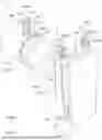
FIG. 1 is an exploded perspective view of an electric compressor according to an embodiment of the present invention.
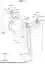
FIG. 2 is a perspective view of the electric compressor.
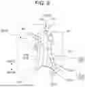
FIG. 3 is a conceptual diagram for explaining an example of a state in which the electric compressor is mounted on an installation object.
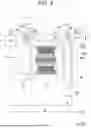
FIG. 4 is a cross-sectional view of a first mounting leg of the electric compressor.
FIG. 5 is a cross-sectional view of a second mounting leg of the electric compressor.
FIG. 6 is an enlarged perspective view including a first mounting leg according to a modification.
FIG. 7 is an enlarged perspective view including a first mounting leg according to another modification.
DESCRIPTION OF EMBODIMENTS
In the following, an embodiment of an electric compressor according to the present invention will be described with reference to the drawings.
FIGS. 1 to 3 are diagrams for explaining an electric compressor 1 according to an embodiment of the present invention. Specifically, FIG. 1 is an exploded perspective view of the electric compressor 1, FIG. 2 is a perspective view of the electric compressor 1, and FIG. 3 is a conceptual diagram for explaining an example of a state when the electric compressor 1 is mounted on a predetermined object C. FIG. 3 is a partially schematic sectional view.
The electric compressor 1 is mounted on a vehicle as a part of a vehicle air conditioner, for example, and is used as a device that sucks, compresses, and discharges a refrigerant for vehicle air conditioning. The electric compressor 1 is mounted on a part of a vehicle body of a vehicle in an engine room of the vehicle, for example. That is, in the present embodiment, the object C on which the electric compressor 1 is mounted is a part of the vehicle body.
Referring to FIGS. 1 and 2, the electric compressor 1 includes an electric motor 10, a compression mechanism 20 driven by the electric motor 10, an inverter 30 that drives the electric motor 10, a casing 40 in which the electric motor 10, the compression mechanism 20, and the inverter 30 are housed, and a mounting portion 50. That is, the electric compressor 1 is configured as a so-called inverter-integrated electric compressor.
Referring to FIG. 3, the electric motor 10 includes a stator 11 in an annular shape, a rotor 12, and a coil (not shown) wound around the stator 11. As the electric motor 10, for example, a three-phase AC motor is applied.
The stator 11 is formed in an annular shape. The stator 11 is made of, for example, a plurality of silicon steel plates laminated on each other.
The rotor 12 is disposed radially inside the stator 11 and has a plurality of magnetic poles (not shown). Into a through hole formed at the radial center of the rotor 12, a rotating shaft 10a is fitted. The rotating shaft 10a is provided integrally with the rotor 12. The longitudinal ends of the rotating shafts 10a are rotatably supported inside the casing 40. The rotor 12 is rotatably supported on the radially inner side of the stator 11 via the rotating shaft 10a. When a magnetic field is generated in the stator 11 by the power supply from the inverter 30, a rotational force acts on the rotor 12, and thus the rotating shaft 10a is rotationally driven. One end portion of the rotating shaft 10a is connected to the compression mechanism 20 such hat the compression mechanism 20 is drivable.
The compression mechanism 20 is driven by the electric motor 10 to compress a refrigerant. The compression mechanism 20 and the electric motor 10 are disposed in series inside the casing 40. The compression mechanism 20 is not specifically limited, but is a scroll compression mechanism including a fixed scroll and a movable scroll. Note that the compression mechanism 20 is not limited to a scroll type, and an appropriate type of compression mechanism such as a reciprocating type that reciprocates a piston connected to a swing plate can be adopted.
The inverter 30 converts, for example, a direct current from a battery (not shown) of the vehicle into an alternating current, and supplies the alternating current to the electric motor 10.
The casing 40 constitutes an outer shell of the electric compressor 1. The electric motor 10, the compression mechanism 20, and the inverter 30 are housed inside the casing 40. The casing 40 is provided with a suction port 40a and a discharge port 40b to which a refrigerant pipe (not shown) of the vehicle air conditioner is connected. The positions of the suction port 40a and the discharge port 40b will be described later.
In the electric compressor 1, when the electric motor 10 is driven by the inverter 30, the electric motor 10 drives the compression mechanism 20 via the rotating shaft (output shaft) 10a of the electric motor 10. Thus, the electric compressor 1 sucks the refrigerant (low-pressure refrigerant) of the vehicle air conditioner from the suction port 40a, compresses the refrigerant by the compression mechanism 20, and discharges the compressed refrigerant (high-pressure refrigerant) from the discharge port 40b.
The mounting portion 50 is formed in the casing 40 and mounts the casing 40 to a predetermined object C (here, the vehicle body). The mounting portion 50 is formed integrally with the casing 40. The structure, position, and the like of the mounting portion 50 will be described later.
The stator 11 of the electric motor 10 is incorporated (fitted) inside the casing 40 by shrink fitting. During the shrink fitting, the casing 40 (specifically, a motor casing 41 to be described later) is heated. Therefore, when the mounting portion 50 is heated together with the casing 40 at the time of shrink fitting (assembling) of the stator 11, the mounting portion 50 is deformed, and the position accuracy of the mounting portion 50 might decrease due to the assembly of a stator. On the other hand, the electric compressor 1 has a structure described below.
In the electric compressor 1, the casing 40 includes the motor casing 41 in which the electric motor 10 is housed, a compression mechanism casing 42 in which the compression mechanism 20 is housed, and an inverter casing 43 in which the inverter 30 is housed. That is, the casing 40 is separated into at least the motor casing 41, the compression mechanism casing 42, and the inverter casing 43. The casing members (41, 42, 43) are formed mainly by casting, for example. The casing members (41, 42, 43) are integrally fastened by a fastening device such as bolts to constitute the casing 40.
In the present embodiment, the motor casing 41 is provided between the compression mechanism casing 42 and the inverter casing 43. The motor casing 41 has, for example, a cylindrical portion 411 formed in a substantially cylindrical shape so as to surround the periphery of the electric motor 10. One end face of the cylindrical portion 411 is in contact with the compression mechanism casing 42, and the other end face of the cylindrical portion 411 is in contact with the inverter casing 43. The suction port 40a is provided at an inverter-side end of the cylindrical portion 411 of the motor casing 41. The stator 11 of the electric motor 10 is assembled inside the cylindrical portion 411 of the motor casing 41 by shrink fitting. During this shrink fitting, only the motor casing 40 of the casing 41 is heated.
In the present embodiment, the compression mechanism casing 42 has a cylindrical portion 421 formed in a substantially cylindrical shape so as to surround the periphery of the compression mechanism 20. One opening of the cylindrical portion 421 is closed. An opening side end face of the cylindrical portion 421 of the compression mechanism casing 42 abuts on an end face of the cylindrical portion 411 of the motor casing 41. The outer diameter of the cylindrical portion 421 of the compression mechanism casing 42 is matched with the outer diameter of the cylindrical portion 411 of the motor casing 41.
In the present embodiment, the inverter casing 43 includes, for example, an inverter case main body portion 431 and an inverter cover portion 432. The inverter casing 43 is formed in a substantially box shape that is long in a direction orthogonal to a central axis X of the rotating shaft 10a of the electric motor 10. The inverter case main body portion 431 has a bottom wall 431a fixed to the motor casing 41 and a side wall 431b extending from an edge of the bottom wall 431a. The bottom wall 431a is formed in a substantially rectangular shape in a plan view, and the side wall 431b is formed in a substantially rectangular annular shape in a plan view as viewed toward the bottom wall 431a. The inverter cover portion 432 is formed in a substantially rectangular flat plate shape in a plan view. The inverter cover portion 432 is fixed to the inverter case main body portion 431 with bolts or the like so as to close the opening of the inverter case main body portion 431. To the bottom wall 431a of the inverter case main body portion 431, a substrate constituting the inverter 30 is fixed.
In the present embodiment, the inverter casing 43 protrudes toward the object C from the outer surface of the compression mechanism casing 42 and the outer surface of the motor casing 41. Specifically, in a state where the inverter casing 43 is fixed to the motor casing 41, one end side portion in the longitudinal direction of the inverter casing 43 protrudes (projects) to the object C side from the outer surface of the compression mechanism casing 42 and the outer surface of the motor casing 41.
Referring to FIG. 3, in the present embodiment, the object C is located above the casing 40, and the casing 40 is suspended below the object C via the mounting portion 50. That is, the electric compressor 1 is suspended below the object C via the mounting portion 50.
Next, the structure, position, shape, and the like of the mounting portion 50 will be described in detail.
The mounting portion 50 includes a first mounting leg 51 provided in the compression mechanism casing 42 and a second mounting leg 52 provided in the inverter casing 43. That is, the mounting portion 50 includes a plurality of mounting legs, a part (first mounting leg 51) of the plurality of mounting legs is provided in the compression mechanism casing 42, and the rest (second mounting leg 52) of the plurality of mounting legs is provided in the inverter casing 43. Therefore, the plurality of mounting legs is provided in a casing part of the casing 40 avoiding the motor casing 41.
Specifically, the first mounting leg 51 is provided at the top of the cylindrical portion 421 of the compression mechanism casing 42 on the object C side. The second mounting leg 52 is provided on the upper surface of the inverter casing 43, that is, the surface of the side wall 431b of the inverter case main body portion 431 on the object C side. The first mounting leg 51 and the second mounting leg 52 extends linearly toward the object C.
In the present embodiment, the number (figures) of the first mounting legs 51 is one (one), and the number (figures) of the second mounting legs 52 is two (two). Therefore, in the present embodiment, the electric compressor 1 is suspended below the object C via three hanging tools (one first mounting leg 51 and two second mounting legs 52). Specifically, in a plan view of the casing 40 viewed from above, one first mounting leg 51 is disposed at the top of the cylindrical portion 421 so as to overlap the central axis X, and the two second mounting legs 52 are provided to be separated from each other in the direction orthogonal to the central axis X on the upper surface of the side wall 431b of the inverter casing 43. In a plan view of the casing 40 viewed from above, the central axis line X is located between the two second mounting legs 52. The center of gravity of electric compressor 1 is located in a region inside a virtual triangle formed by the one first mounting leg 51 and the two second mounting legs 52 in a plan view of casing 40 viewed from above.
In the present embodiment, a seat portion (511, 521) having a seating face (51a, 52a) in contact with the object C is formed at the distal ends of the first mounting leg 51 and the second mounting leg 52. The seat portion (511, 521) is formed with a female screw (51b, 52b). The seating face 51a of the seat portion 511 of the first mounting leg 51 and the seating face 52a of the seat portion 521 of the second mounting leg 52 are located on the same virtual plane P.
Specifically, the seat portions (511, 521) are formed in a disk shape, and the seating faces (51a, 52a) are, for example, a flat circular surface constituted of the end faces of the seat portions (511, 521). The female screw (51b, 52b) is formed downward from the seating face (51a, 52a) to a predetermined depth, for example.
The female screw (51b, 52b) is screwed with a screw portion of a bolt inserted through a through hole not shown formed in the object C. Thus, the seat portion 511 of the first mounting leg 51 and the seat portion 521 of the second mounting leg 52 are fastened to the object C. As a result, the casing 40 is mounted on the lower surface of the object C so as to be suspended below the object C via the three mounting legs (51, 52, 52).
In the present embodiment, a total length L1 of the first mounting leg 51 is longer than a total length L2 of the second mounting leg 52. Specifically, here, the first mounting leg 51 is formed longer than the second mounting leg 52 by a distance corresponding to a step in the vertical direction between the top of the cylindrical portion 421 of the compression mechanism casing 42 and the upper surface of the inverter casing 43.
In the present embodiment, the first mounting leg 51 includes the seat portion 511 described above, a leg main body 512 formed in a columnar shape (in this case, a cylindrical shape), and a reinforcing rib 513 extending in the leg portion lateral direction along an outer surface (outer peripheral surface) of leg main body 512. Similarly, the second mounting leg 52 includes the seat portion 521 described above, a leg main body 522 formed in a columnar shape, and a reinforcing rib 523 extending in the leg portion lateral direction along the outer peripheral surface of a leg main body 522. FIG. 4 is a cross-sectional view of the first mounting leg 51, and FIG. 5 is a cross-sectional view of the second mounting leg 52. FIGS. 4 and 5 are cross-sectional views of the seat portion (511, 521) as viewed from the back surface side (the side opposite to the seating face (51a, 52a)).
Specifically, referring to FIG. 4, the reinforcing rib 513 of the first mounting leg 51 includes a first rib 513a extending in the leg portion lateral direction along the motor casing side portion (top portion) on the outer surface (outer peripheral surface) of the leg main body 512, and a second rib 513b and a third rib 513c orthogonal to the first rib 513a. That is, the first mounting leg 51 has a substantially T-shaped cross section with the first rib 513a facing the motor casing side. The first rib 513a extends parallel to the central axis X at a position overlapping the central axis X in the cross-sectional view, and the second rib 513b and the third rib 513c extend in a direction orthogonal to the central axis X. Referring to FIGS. 1 to 3, in the present embodiment, each rib (513a, 513b, 513c) of the first mounting leg 51 is formed away from the outer surface of the leg main body 512 toward the cylindrical portion 421 of the compression mechanism casing 42. Specifically, the edge portions of the ribs (513a, 513b, 513c) are formed in an arc shape as a whole, and the ribs (513a, 513b, 513c) have an arc-shaped contour (arc fillet). In addition, in the present embodiment, the base end portion (root portion) of the first rib 513a of the first mounting leg 51 is located closer to the leg main body 512 side from the motor casing side end face 421a of the cylindrical portion 421.
Referring to FIG. 5, the reinforcing rib 523 of each of the second mounting legs 52 includes a fourth rib 523a extending in the leg portion lateral direction along the motor casing side portion (top portion) on the outer surface (outer peripheral surface) of the leg main body 522, and a fifth rib 523b and a sixth rib 523c orthogonal to the fourth rib 523a. That is, the second mounting legs 52 have a substantially T-shaped cross section with the fourth rib 523a facing the motor casing side. The fourth rib 523a extends parallel to the central axis X, and the second rib 513b and the third rib 513c extend in a direction orthogonal to the central axis X. Referring to FIGS. 1 to 3, in the present embodiment, each rib (523a, 523b, 523c) of the second mounting leg 52 is formed away from the outer surface of the leg main body 522 toward the cylindrical portion 421 of the compression mechanism casing 42. Specifically, also in the second mounting leg 52, the edge of each rib (523a, 523b, 523c) is formed in an arc shape as a whole, and each rib (523a, 523b, 523c) has an arc-shaped contour (arc fillet).
As described above, in the electric compressor 1 according to the present embodiment, the casing 40 includes the motor casing 41, the compression mechanism casing 42, and the inverter casing 43. The mounting portion 50 formed in the casing 40 that mounts the casing 40 to the object C includes the first mounting leg 51 provided in the compression mechanism casing 42 and the second mounting leg 52 provided in the inverter casing 43. Therefore, the plurality of mounting legs (the first mounting portion 51 and the second mounting portion 52) constituting the mounting portion 50 is provided in the casing part of the casing 40 avoiding the motor casing 41. That is, the mounting portion 50 is provided in the compression mechanism casing 42 and the inverter casing 43, which are casing parts separated from the motor casing 41 heated at the time of shrink fitting of the stator 11. As a result, the mounting portion 50 is not heated together with the motor casing 41 at the time of shrink fitting of the stator 11, and the position accuracy of the mounting portion 50 falls within the range of the intended necessary accuracy. Therefore, deterioration in the position accuracy of the mounting portion 50 due to the assembly of a stator is stopped. As described above, the electric compressor 1 has a structure capable of stopping deterioration in position accuracy of the mounting portion 50 due to the assembly of a stator.
In addition, since the inverter casing 43 is fixed to the object C via the second mounting leg 52, the inverter casing 43 is stably supported. As a result, vibration of the circuit components of the inverter 30 is suppressed.
In the present embodiment, the number of the first mounting legs 51 is one, and the number of the second mounting legs 52 is two. Thus, the mounting portion 50 can stably mount the casing 40 to the object C with a simple structure by the three-point support structure using the three mounting legs (51, 52, 52).
In the present embodiment, a seat portion (511, 521) having a seating face (51a, 52a) in contact with the object C is formed at the distal ends of the first mounting leg 51 and the second mounting leg 52. The seat portion (511, 521) is formed with a female screw (51b, 52b). Thus, the electric compressor 1 is easily mounted on the object C via the mounting portion 50 only by screwing the screw portion of the bolt extending from the object C side to the female screw (51b, 52b).
In the present embodiment, the seating face 51a of the seat portion 511 of the first mounting leg 51 and the seating face 52a of the seat portion 521 of the second mounting leg 52 are located on the same virtual plane P. Thus, the electric compressor 1 is easily mounted on the object C when the mounting site (fastening site) of the object C to the electric compressor 1 is located on the same virtual plane P.
In the present embodiment, the total length L1 of the first mounting leg 51 is longer than the total length of the second mounting leg 52, and the first mounting leg 51 includes the leg main body 512 and the reinforcing rib 513 extending in the leg portion lateral direction along the outer surface of leg main body 512. Thus, the strength of the first mounting leg 51 is enhanced by the reinforcing rib 513 in the case where the inverter casing 43 protrudes to the object C side from the outer surface of the compression mechanism casing 42 and the outer surface of the motor casing 41, and the first mounting leg 51 has to be formed longer than the second mounting leg 52. As a result, the electric compressor 1 is more firmly mounted on the object C, and durability against vibration is improved.
In the present embodiment, the motor casing 41 is provided between the compression mechanism casing 42 provided with the first mounting leg 51 and the inverter casing 43 provided with the second mounting leg 52. That is, the mounting portion 50 is provided to be distributed to one end portion and the other end portion in the longitudinal direction of the electric compressor 1. Thus, the electric compressor 1 is supported (suspended) by both end supports, and a stable supporting structure of the electric compressor 1 is constructed. In addition, the first mounting leg 51 includes the leg main body 512, the first rib 513a, the second rib 513b, and the third rib 513c, and has a T-shaped cross section as a whole. Thus, the strength of the first mounting leg 51 longer than the second mounting leg 52 is more effectively enhanced, and durability against vibration is more effectively improved.
In the present embodiment, each rib (513a, 513b, 513c) of the first mounting leg 51 is formed so as to be away from the outer surface (outer peripheral surface) of the leg main body 512 as approaching the cylindrical portion 421 of the compression mechanism casing 42. Thus, stress concentration on the base portion of the first mounting leg 51 at the time of occurrence of vibration or the like is reduced, strength of the base portion of the first mounting leg 51 is improved, and durability against vibration is remarkably improved. The same applies to the second mounting leg 52. In the following, modifications of the electric compressor 1 of the present embodiment will be described.
FIG. 6 is an enlarged perspective view for explaining a modification of the first mounting leg 51. In the present embodiment, the base end portion of the first rib 513a of the first mounting leg 51 is located at a position farther toward the leg main body 512 side from the motor casing side end face 421a of the cylindrical portion 421, but the present invention is not limited to this, and may extend to the motor casing side end face 421a of the cylindrical portion 421 as shown in FIG. 6.
Specifically, referring to FIG. 6, the first rib 513a of the first mounting leg 51 has a rib main body 513a1 and a rib root 513a2. The rib main body 513a1 is formed so as to be away from the outer surface (outer peripheral surface) of the leg main body 512 toward the cylindrical portion 421 of the compression mechanism casing 42. Specifically, the edge portion of the rib main body 513a1 is formed in an arc shape, and the rib main body 513a1 has an arc-shaped contour (arc fillet). The rib root 513a2 is a portion constituting the base end portion of the first rib 513a. The rib root 513a2 connects the rib main body 513a1 to the outer surface of the cylindrical portion 421 of the compression mechanism casing 42, and extends from the outer surface (outer peripheral surface) of the leg main body 512 to the position of the motor casing side end face 421a of the cylindrical portion 421. That is, the rib root 513a2 protrudes radially outward from the outer peripheral surface of the cylindrical portion 421, and the rib main body 513a1 extends upward continuously to the end of the rib root 513a2. Thus, the strength of the entire base end portion (root portion) of the first rib 513a is reinforced by the rib root 513a2 formed to be wide and maximum, and the stress concentration in the rib root 513a2 (base end portion of the first mounting leg 51) is more effectively reduced. Specifically, the stress (stress concentration) at the motor casing side end at the base end portion of the first rib 513a is remarkably reduced.
In addition, although not shown, each rib (513a, 513b, 513c, 523a, 523b, 523c) may linearly extend in the vertical direction. Furthermore, the number of the first mounting legs 51 is not limited to one but may be two or more, and the number of the second mounting legs 52 is not limited to two but may be one or three or more.
In some cases, the mounting site (fastening site) of the object C to the electric compressor 1 is not located on the same virtual plane P. In this case, the total length L1 of the first mounting leg 51 and the total length L2 of the second mounting leg 52 are appropriately set according to the distance between the mounting site and the compression mechanism casing 42 and the distance between the mounting site and the inverter casing 43 in the object C. There may be the case where the total length L1 of the first mounting leg 51 is substantially equal to the total length L2 of the second mounting leg 52 (see FIG. 7 which is an enlarged perspective view for describing another modification), or the case where the total length L1 of the first mounting leg 51 is shorter than the total length L2 of the second mounting leg 52 (not shown).
The description of the present embodiment is an example for describing the present invention, and does not limit the invention described in the claims. In addition, the configuration of the components of the present invention is not limited to the foregoing embodiment, and various modifications are feasible within the technical scope described in the claims.
LIST OF REFERENCE SIGNS
-
- 1 Electric compressor
- 10 Electric motor
- 20 Compression mechanism
- 30 Inverter
- 40 Casing
- 41 Motor casing
- 42 Compression mechanism casing
- 421 Cylindrical portion
- 43 Inverter casing
- 50 Mounting portion
- 51 First mounting leg
- 51a Seating face
- 51b Female screw
- 511 Seat portion
- 512 Leg main body
- 513 Reinforcing rib
- 513a First rib
- 513b Second rib
- 513c Third rib
- 513a1 Rib main body
- 513a2 Rib root
- 52 Second mounting leg
- 52a Seating face
- 52b Female screw
- 521 Seat portion
- 522 Leg main body
- 523 Reinforcing rib
- 523a Fourth rib
- 523b Fifth rib
- 523c Sixth rib
- C Object
- L1 Total length of first mounting leg
- L2 Total length of second mounting leg
- P Virtual plane
Claims
1. An electric compressor comprising: an electric motor; a compression mechanism driven by the electric motor; an inverter that drives the electric motor; a casing in which the electric motor, the compression mechanism, and the inverter are housed; and a mounting portion that is formed in the casing and mounts the casing on a predetermined object, wherein
the casing includes a motor casing in which the electric motor is housed, a compression mechanism casing in which the compression mechanism is housed, and an inverter casing in which the inverter is housed, and
the mounting portion includes a first mounting leg provided in the compression mechanism casing and a second mounting leg provided in the inverter casing.
2. The electric compressor according to claim 1, wherein
the number of the first mounting legs is one, and the number of the second mounting legs is two.
3. The electric compressor according to claim 1, wherein
a seat portion having a seating face in contact with the object is formed at a distal end of the first mounting leg and the second mounting leg, and
a female screw is formed in the seat portion, and
the seating face of the first mounting leg and the seating face of the second mounting leg are located on an equal virtual plane.
4. The electric compressor according to claim 1, wherein
the inverter casing protrudes toward an object side from an outer surface of the compression mechanism casing and an outer surface of the motor casing, and
a total length of the first mounting leg is longer than a total length of the second mounting leg, and
the first mounting leg includes a leg main body formed in a columnar shape, and a reinforcing rib extending in a leg portion lateral direction along an outer surface of the leg main body.
5. The electric compressor according to claim 4, wherein
the motor casing is provided between the compression mechanism casing and the inverter casing,
the compression mechanism casing includes a cylindrical portion surrounding a periphery of the compression mechanism, and
the reinforcing rib of the first mounting leg includes a first rib extending in the leg portion lateral direction along a motor casing side portion of an outer surface of the leg main body and a second rib and a third rib orthogonal to the first rib.
6. The electric compressor according to claim 5, wherein the first rib, the second rib, and the third rib are formed away from an outer surface of the leg main body toward the cylindrical portion of the compression mechanism casing.
7. The electric compressor according to claim 5, wherein the first rib includes a rib main body formed so as to be away from an outer surface of the leg main body toward the cylindrical portion of the compression mechanism casing, and a rib root connecting the rib main body to an outer surface of the cylindrical portion of the compression mechanism casing, the rib root extending from the outer surface of the leg main body to a motor-casing-side end face position of the cylindrical portion.
8. The electric compressor according to claim 1, wherein
the object is located above the casing, and
the casing is suspended below the object via the mounting portion.
Images & Drawings included:


Sources:
- United States Patent and Trademark Office - verify current appl. status at the USPTO↗
Similar patent applications:
- » 20200232453
Control device for electric compressor, electric compressor, air conditioning device for moving object, and method for controlling electric compressor - » 20240166024
ELECTRIC COMPRESSOR CONTROL DEVICE, ELECTRIC COMPRESSOR, AND ELECTRIC COMPRESSOR CONTROL METHOD - » 20190052070
Electric wire lead-in part structure of electric compressor, and electric compressor and shield electric wire provided with same - » 20150214863
Control device of electric sealed compressor, electric sealed compressor apparatus, and home appliance comprising control device and electric sealed compressor apparatus - » 20090315418
Electric wire holding structure for electric compressor and electric wire holding method for electric compressor - » 20090104055
ELECTRIC COMPRESSOR MANUFACTURING METHOD AND ELECTRIC COMPRESSOR - » 20170072773
Electric compressor control system and electric compressor for vehicular air conditioning device provided with said system - » 20250317034
ELECTRIC COMPRESSOR CONTROL BOARD AND ELECTRIC COMPRESSOR - » 20100232982
Control device for electric compressor and start control method of electric compressor - » 20170037858
Electric compressor and method for producing an electric compressor
Recent applications in this class:
- » 20250059975 2025-02-20
REFRIGERANT COMPRESSOR - » 20250020125 2025-01-16
Compressor and Air Conditioner - » 20240337261 2024-10-10
ELECTRIC COMPRESSOR - » 20240240639 2024-07-18
COMPRESSOR UNIT - » 20240218880 2024-07-04
ASSEMBLY AND ELECTRIC COMPRESSOR WITH NON-RADIAL CLAMPING FEATURE - » 20230033477 2023-02-02
Motor-driven compressor - » 20220333600 2022-10-20
Inverter manufacturing equipment - » 20200347847 2020-11-05
Hydraulic power unit - » 20200325898 2020-10-15
Integrated motor and pump including axially placed coils - » 20190277290 2019-09-12
Electric compressor having electrical connection unit, and stator assembly for the same