Fan
US20250354563A1
2025-11-20
19/209,674
2025-05-15
Smart Summary: A fan is designed to blow air in multiple directions from a tall opening. It has a housing that takes in air from the sides and pushes it out through a narrow, vertical outlet. Inside, a special shape helps direct the air upward while also allowing some to flow out horizontally. This creates a mix of airflow that goes both forward and upward without needing any moving parts to change direction. Additionally, the fan can have a base that moves side to side and an arm that can pivot for even more control over where the air goes. 🚀 TL;DR
Abstract:
A fan configured to generate multidirectional airflow from a vertically elongated main outlet is disclosed. The fan includes a housing with a blower assembly that receives ambient air through lateral intake openings and emits air through a narrow, vertically extending outlet. Internally, a blower housing with a curved wall directs airflow into a duct chamber that includes an upwardly angled wall surface. The blower outlet is spaced below the main outlet, and the duct geometry, including the angled wall, induces a portion of the airflow to adhere to the surface and exit the outlet in an upward direction. The remaining airflow exits horizontally, producing a compound airflow pattern comprising both forward and upward components without any movable louvers or tilt mechanisms. An oscillating base and optional pivoting support arm allow further directional control.
Inventors:
- Byron Loibl 13 🇺🇸 Wichita, KS, United States
- Gregory Pease 23 🇺🇸 Andover, KS, United States
- Brian Cartwright 5 🇺🇸 Wichita, KS, United States
- Anthony Fischer 6 🇺🇸 Wichita, KS, United States
- Joshua Weed 5 🇺🇸 Wichita, KS, United States
Applicant:
Interested in similar patents?
Get notified when new applications in this technology area are published.
Classification:
F04D29/4226 » CPC main
Details, component parts, or accessories; Casings; Connections of working fluid for radial or helico-centrifugal pumps especially adapted for elastic fluid pumps Fan casings
F04D25/06 » CPC further
Pumping installations or systems; Units comprising pumps and their driving means the pump being electrically driven
F04D25/08 » CPC further
Pumping installations or systems; Units comprising pumps and their driving means the working fluid being air, e.g. for ventilation
F04D29/42 IPC
Details, component parts, or accessories; Casings; Connections of working fluid for radial or helico-centrifugal pumps
Description
RELATED APPLICATIONS
This application claims the benefit under 35 U.S.C. § 119 (e) of U.S. Provisional Patent Application Ser. No. 63/648,070, filed on May 15, 2024, titled “FAN,” the entire contents of which are incorporated by reference herein.
FIELD OF THE INVENTION
The invention relates to a fan, and particularly, a fan having a slim profile and oscillating functionality to produce a compound airflow pattern comprising both a forward-projected and an upward-directed airflow component, achieved through internal geometry and ducting configurations.
BACKGROUND OF THE INVENTION
Electrically powered fans are widely used in residential, commercial, and industrial settings to promote air circulation, improve thermal comfort, and facilitate cooling of spaces. These fans typically include a housing containing a motorized impeller or blower that draws in ambient air and expels it through a front outlet or grille. Common variants include table fans, floor-standing fans, pedestal fans, and tower fans, with directional airflow commonly achieved through pivoting heads, oscillation mechanisms, or manually adjustable louvers.
While traditional fans perform adequately for single-direction airflow projection, they are limited in their ability to simultaneously circulate air in multiple directions, particularly in a vertical direction without mechanical repositioning. Users often resort to manually tilting the fan head or adjusting movable louvers to direct airflow upward, which introduces mechanical complexity, requires user intervention, and can compromise the visual aesthetics or durability of the device. Additionally, such adjustable components are susceptible to mechanical wear over time and may introduce noise or looseness in operation.
Tower fans, while offering compact vertical profiles, often emit airflow in a horizontal plane and lack mechanisms to direct air vertically without reorientation. Attempts to achieve multidirectional airflow in existing designs typically involve active elements such as servo-controlled vents or multiple blower outputs, which increase cost, complexity, and power consumption. Furthermore, such designs often require additional space or compromise the uniformity and velocity of the emitted airflow.
There is therefore a need in the art for a fan that can produce both a forward airflow and an upward airflow component from a compact, fixed outlet without requiring mechanical redirection or adjustment by the user. Such a fan would ideally maintain a clean, vertically oriented profile suitable for modern aesthetic environments, while providing efficient multidirectional air distribution and minimizing component complexity.
The present invention addresses these and other shortcomings by introducing a fan configured with a uniquely engineered volute, internal duct geometry, and outlet configuration that together induce upward deflection of a portion of the airflow as it exits the outlet. This is accomplished without relying on any movable airflow-directing components and instead leverages passive aerodynamic principles such as the Coanda effect and pressure differentials within an elongated duct chamber. The result is a fan capable of delivering both forward and upward airflow simultaneously from a single outlet aperture, in a durable, reliable, and user-friendly package. Additional embodiments further provide oscillation, pivoting mechanisms, and modular support structures, offering enhanced customization of airflow behavior while maintaining a low profile and high design fidelity.
SUMMARY OF THE INVENTION
The present invention is directed at a fan configured to produce directional airflow through a vertically elongated outlet, with internal geometries specifically engineered to influence the path of airflow within the housing. More particularly, the invention relates to a fan that utilizes a strategically positioned blower housing and a uniquely contoured air duct chamber to facilitate and control the trajectory of airflow emitted through the fan's front-facing outlet.
In one example of the invention, the fan includes a fan housing having a main outlet formed along a front face of the housing. A blower assembly is positioned within the housing and comprises a blower and a motor configured to rotate the blower to generate airflow. The blower is at least partially enclosed by a blower housing (or volute), which defines a blower outlet positioned in a lower portion of the fan housing and rearward of the main outlet. An air duct chamber is defined between the blower outlet and the main outlet, and the air duct chamber includes an angled interior wall that extends upward from the blower outlet toward an upper portion of the main outlet. The geometric arrangement of these components enables a portion of the airflow to follow the angled wall and exit from the upper portion of the outlet.
In another example, the fan comprises a housing having a defined length, height, and width, and includes a vertically extending main outlet having a width that is less than half the width of the fan housing. The reduced width of the outlet compresses the outgoing airflow, increasing its velocity and directionality. A blower positioned within the housing includes one or more blades and a motor and is housed within a blower housing that includes a blower outlet. The blower outlet is positioned within a lower portion of the main outlet region to support both horizontal and vertical airflow profiles depending on internal duct configuration.
In another example, the air duct between the blower outlet and the main outlet includes an upwardly angled wall that extends greater than half the distance between the blower outlet and the main outlet. The extended angled wall creates a flow boundary that induces a portion of the airflow to follow an upward path due to aerodynamic effects, including the Coanda effect, thereby generating a compound airflow pattern comprising both forward and upward airflow components. The angled wall and outlet configuration allow for the redirection of airflow without the use of mechanical louvers, pivoting grilles, or other movable components.
Other devices, apparatus, systems, methods, features and advantages of the invention are or will become apparent to one with skill in the art upon examination of the following figures and detailed description. It is intended that all such additional systems, methods, features and advantages be included within this description, and be within the scope of the invention, and be protected by the accompanying claims.
BRIEF DESCRIPTION OF THE FIGURES
The invention can be better understood by referring to the following figures. The components in the figures are not necessarily to scale, emphasis instead being placed upon illustrating the principles of the invention. In the figures, like reference numerals designate corresponding parts throughout the different views.
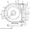
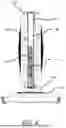
FIG. 1 is a front perspective view of the right side of one example of an implementation of a fan of the present invention.
FIG. 2 is a top view of the fan of FIG. 1.
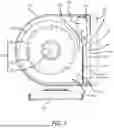
FIG. 3 is a left side internal view of the fan housing of the fan of FIG. 1.
FIG. 4 is a front view of the fan of FIG. 1.
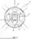
FIG. 5 is a top internal view the oscillating mechanism of the fan of FIG. 1.
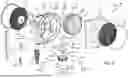
FIG. 6 is an exploded view of the fan of FIG. 1.
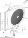
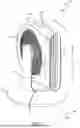
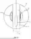
FIG. 7 is a front perspective view of the left side of another example of an implementation of a fan of the present invention.
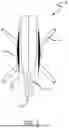
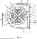
FIG. 8 is a top view of the fan of FIG. 7.
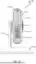
FIG. 9 is a left side internal view of the fan housing of the fan of FIG. 7.
FIG. 10 is a front view of the fan of FIG. 7.
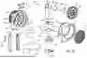
FIG. 11 is an exploded view of the fan of FIG. 7.
DESCRIPTION OF THE INVENTION
In this disclosure, all “aspects,” “examples,” “embodiments,” and “implementations” described are considered to be non-limiting and non-exclusive. Accordingly, the fact that a specific “aspect,” “example,” “embodiment,” or “implementation” is explicitly described herein does not exclude other “aspects,” “examples,” “embodiments,” and “implementations” from the scope of the present disclosure even if not explicitly described. In this disclosure, the terms “aspect,” “example,” “embodiment,” and “implementation” are used interchangeably, i.e., are considered to have interchangeable meanings.
Further, in this application, the terms “substantially,” “approximately,” or “about,” when modifying a specified numerical value, may be taken to encompass a range of values that include +/−10% of such numerical value. Further, terms such as “communicate,” and “in communication with,” or “interfaces” or “interfaces with” (for example, a first component “communicates with” or “is in communication with” a second component) are used herein to indicate a structural, functional, mechanical, electrical, signal, optical, magnetic, electromagnetic, ionic or fluidic relationship between two or more components or elements. As such, the fact that one component is said to communicate or interface with a second component is not intended to exclude the possibility that additional components may be present between, and/or operatively associated or engaged with, the first and second components.
For purposes of reference and description, the fan 100, 700 of the present invention is considered to have a horizontal x-axis (x), vertical y-axis (y) and a width z-axis (z), as shown in FIGS. 1 and 7 along which the components of the fan 100, 700 are positioned relative to each other. Terms such as “axial” and “axially” are assumed to refer to the respective axis or any direction or axis parallel to the device axis, unless indicated otherwise or the context dictates otherwise. For convenience, movement relative to a device axis may alternatively encompass movement relative to an axis that is parallel to the device axis that is specifically illustrated in FIG. 1, unless the context dictates otherwise. Thus, linear translation “along the device axis z” is not limited to translation directly on (coincident with) the device axis, but also encompasses translation parallel to the device axis z, depending on the context. Similarly, rotation “about the device axis y” also encompasses rotation about an axis that is parallel to the device axis y, depending on the context.
Further, the fan of the present invention is also considered to have a height (h), length (l) and width (w), as also shown most notably shown by arrows in FIGS. 1 and 7. It should be understood that the height (h), length (l) and width (w) directions also applies to all internal components of fan 100.
As illustrated and discussed in the following, examples of a fan that may pivot and oscillate is provided. In the example, the fan is a portable, free-standing fan. “Portable” being defined as having the ability to be carried or moved with ease. “Free standing” being defined as having the ability to remain stable and upright without external restraints. It should further be understood that the term “fan” may be interchangeably used with the terms “air blower, “air circulator” or any other term that refers to an apparatus that creates a current of air for cooling and/or heating.
As will be illustrated and discussed in detail below, the fan of the present invention incorporates the combination of a pivoting mechanism and oscillating mechanism. The pivoting mechanism allows the fan head to pivot along the vertical axis or y-axis of the fan relative to a support arm, and the oscillating mechanism allows the fan head to oscillate horizontally along the horizontal axis or x-axis relative to the fan base. Such combination allows for versatile adjustability and directional control. Additionally, unlike conventional fans, which primarily redirect the entire airflow direction by changing the fan's physical orientation, the present invention decouples airflow redirection from physical movement by generating a built-in upward airflow vector through internal structural design. In general, the present invention provides a fan housed in a slim, vertically elongated enclosure extending along the height (h) or y-axis that is engineered to produce a multidirectional airflow output—specifically, one that exhibits both straight-line airflow (i.e., airflow emitted along the x-axis) and an upwardly deflected airflow (i.e., airflow emitted along the y-axis)—without requiring any repositioning or reorientation of the fan housing, outlet grill, or any manually maneuverable flow-directing structures during use. This upward airflow is not the result of any active mechanism or externally adjustable louver but is instead generated passively via innovative internal ducting geometry, carefully placed blower outlet positioning, and aerodynamic flow channeling elements that cooperate to generate a rising airflow plume. This design provides seamless user experience and eliminates the need for mechanical tilt adjustments.
As shown in FIGS. 1-6, one example of a fan 100 of the present invention is illustrated. As shown in FIG. 1, fan 100 includes a fan housing or fan head housing 102 connected to a base 104 via a support arm 108 that attached to the bottom of fan housing 102. Fan head housing 102 houses, in general, a blower assembly 308 positioned within an interior space of fan housing 102 and that receives ambient air through air intake openings 112, 606 for generating airflow. The frontal face of housing 102 also includes main outlet 106. Main outlet 106 is constructed as a vertically extending outlet slit extending along the height of fan 100. Main outlet 106 is dimensioned to be narrow in its width, while spanning a considerable vertical height. Main outlet 106 serves as the final exhaust path for the airflow generated internally by fan 100. The elongated shape and narrow width of main outlet 106 contributes to forming a high-aspect-ratio airflow jet that not only projects air forward but facilitates controlled vertical shearing of the stream. This design enables a uniform distribution of air across an extended height range, thereby providing airflow across both seated and standing user positions.
Fan 100 also includes a controller 110 positioned on the top side of fan housing 102 for controlling the various operations of fan 100. The controller 110 allows the user to toggle between fan speeds, oscillation modes, and power on/off states. In some examples, controller 110 may include capacitive touch inputs, LED indicators, or wireless communication modules for remote operation by remote control 602 or integration into smart home ecosystems.
Base 104 includes one or more legs 114 for supporting fan to remain stable and upright without external restraints on a surface. Base 104 is defined by the portion of fan 100 that supports head housing 102 above a support surface. While one end of support arm 108 is may be fixedly or pivotally attached to fan head housing 102, the other end of support arm 108 may be fixedly attached to base 104 via a plate 116 that oscillates or rotates relative to base 104 via an oscillating or rotating mechanism positioned within base 104.
FIG. 2 is a top view of fan 100. FIG. 2 best illustrates the narrow width of main outlet 106, particularly in relation to the main body of fan housing 102. In particular, the width of main outlet 106 may be half or less than half the width of the main body of fan housing 102. From the top view of fan 100, main outlet 106 is constructed as to be a funnel shape for guiding airflow generated in wider width of main body of fan 100 and channeling and compressing airflow to the front narrow opening. This funnel shape, particularly with respect to its narrow width relative to the width of fan housing 102, effectively reduces the cross-sectional area through which the air is expelled, resulting in an increase in air velocity. This velocity increase caused by the narrow dimension of main outlet 106 is important not only for propulsion but for maximizing the Coanda adherence along the downstream wall 318 of the internal air duct or air duct chamber 322. Such funnel construction in combination with further components of fan 100 discussed in greater detail below contributes to inducing the upward deflection of airflow when exiting fan 100.
FIG. 3 is a left side internal view of the fan housing 102 of fan 100 that specifically illustrates the horizontal and upward airflow (shown in arrows) of the air emitted from main outlet 106 of fan 100. As stated above, fan housing 102 houses blower assembly 308 comprising of blower 302, having one or more blades 304 and a motor 306. Specifically, blower 302 may be a high-RPM centrifugal blower having impeller or backward-inclined fan blades 304 powered by an electric motor 306. In operation, blower 302 receives ambient air through air intake openings 112, 606, positioned at the lateral sides of housing 102, and imparts kinetic energy to the air, converting electrical energy into mechanical airflow. The airflow is then routed through blower housing 310 within fan housing 102. Blower housing 310 may be a volute, which is a well-known term in the art that refers to a spiral or circular-shaped housing or casing having a curved or circular wall 316 that surrounds blower 302. The term “blower housing” may be used interchangeably with “volute” or “volute housing” or with any other term that refers to a housing or casing that surrounds a blower or centrifugal fan.
Blower housing or volute's 310 primary function is to collect and direct airflow generated by the rotating blower 302 and convert some of the dynamic (velocity) energy of the air into static pressure. Volute 310 discharges air through blower outlet/opening or volute outlet/opening 312. Blower opening or volute opening 312 may include an outlet grill 314 that extends along the height of volute opening 312 and acts as a protective cover of volute opening 312 for protecting volute 310 from external objects entering volute 310. Importantly, volute opening or outlet 312 is positioned back from main outlet 106, thereby creating an air duct chamber or cavity 322 therebetween, creating a zone of compression that is fundamental to the upward airflow feature of the present invention. In other words, the volute opening or outlet 312 may also serve to be the inlet for air duct 322. This spatial displacement between the volute opening 312 and main outlet 106 introduces a transitional air duct chamber 322 where air behavior can be shaped and influenced by geometric surfaces before final discharge.
Air duct 322 is defined as the area between blower or volute outlet 312 and main outlet 106 and may at least partially be defined by wall 318. Wall 318 is a flat surface that may extend between the top of volute opening 312 (or top of outlet grill 314) to main outlet 106 at an angle greater than 0 degrees from the dimensional length (l) of fan 100 but lesser than 90 degrees from dimensional length (l) of fan 100. In one example, wall 318 may extend at least greater than half the length (l) of air duct 322. This extended length of wall 318 in combination with its upward angle relative to the dimensional length (l) of fan 100 is critical to inducing upward deflection of the airflow. In particular, wall 318 must be of sufficient length (e.g., at least greater than half the length of air duct 322 as stated above) in order to maximize airflow adherence for redirecting airflow upward from main outlet 106. Additionally, wall 318 is angled obliquely and may incorporate a smooth surface for aerodynamic profiling to facilitate attachment or adherence of the airflow flowing through air duct 322 along the wall surface 318—a behavior governed by the Coanda effect. The Coanda effect causes the airflow, particularly at higher velocities, to adhere to and follow the contour of a nearby surface. In the present case, as the high-velocity air exits volute opening 312 or outlet grill 314 and enters the air duct chamber 322, a portion of the air adheres to the angled upper surface of wall 318 and is thus directed upward before exiting the upper portion or top portion of main outlet 106, thereby creating a distinct and purposeful upward air flow. Simultaneously, the remaining portion of the airflow exits through the lower or bottom portion of main opening 106, preserving a straight-through airflow path. The interface between the volute chamber 310 and the inclined wall 318 serves as a bifurcation point 326 where the airflow naturally divides due to pressure gradients, velocity profiles, and boundary layer effects, thus creating two flow vectors without mechanical intervention. The result is a compound airflow field: a base layer of horizontal or forward-directed air (shown by horizontal arrows in FIG. 3), and an upper stream of air with a pronounced upward vector (shown by upward direction arrows in FIG. 3). This dual-path airflow characteristic creates a rising plume of air that provides vertical circulation without any moving parts beyond the blower fan itself.
The above construction yields an effect functionally analogous to manual tilting of conventional fans but achieves this entirely through fixed geometry and airflow conditioning. Unlike conventional fans with pivotable heads, gimbals, or adjustable louvers, which require user interaction and introducing potential failure points, the present fan achieves continuous upward airflow in a passive, durable, and aesthetically minimalist configuration.
Additionally, airflow simulations and physical testing demonstrate that positioning volute opening 312 or outlet grill 314 at a lower elevation or height (h) relative to main outlet 106 produces a region of relatively lower pressure in the air duct area between the top of volute opening 312 (or top of outlet grill 314) and top of main outlet 106, which draws air upward as it travels through air duct 322. This pressure differential contributes to the vertical vectoring of the airflow. The narrow funnel shape of main outlet 106 also creates a nozzle or compression effect that accelerates the airflow, promoting entrainment of ambient air from the surrounding environment and amplifying the upward flow component through induced drag and lift interactions.
In other examples, wall 318 may extend between the top of volute opening 312 (or top of outlet grill 314) to a vertical wall 324 (which extends along the height (h) of fan 100) that is positioned slightly back or rearward of main outlet 106. Vertical wall 324 may be used as a storage for remote control 602. In one example, wall 324 may further comprise an inset or cradle contour to securely retain remote control 602 against accidental dislodgment. In another example, magnet or other ferromagnetic material 610 may be positioned on wall 324 for allowing remote control 602 to removably magnetically attach to fan 100 for storage purposes. This magnetic coupling provides a seamless and intuitive method for users to stow and retrieve the remote control 602, improving usability and product integration. The placement of the wall 324 adjacent to the airflow path is also configured such that it does not interfere with airflow dynamics or turbulence patterns within air duct 322.
FIG. 4 is a front view of fan 100. FIG. 4 illustrates the height (h) and width (w) of main outlet 106 relative to the height (h) and width (w) of volute opening 312 (or outlet grill 314) and wall portions 318, 324. In particular, volute opening 312 and/or outlet grill 314 is positioned substantially within the lower or bottom portion of air duct 322 or lower or bottom portion of main outlet 106, while wall portions 318, 324 is positioned substantially within the top or upper portion of air duct 322 or top or upper of main outlet 106. In some examples, volute opening 312 and/or outlet grill 314 is positioned in the bottom half of the height of air duct 322 or main outlet 106, while wall portions 318, 324 is positioned in the top half of the height of air duct 322 or main outlet 106. As stated above, volute opening 312 and/or outlet grill 314 are located substantially in the bottom portion of air duct 322 or main outlet 106 such that a vertical distance exists between the top edge of volute opening 312 and/or grill outlet 314 and the top edge of air duct 322 and/or main outlet 106. The air duct chamber 322 and/or main outlet 106 thus comprises two distinct segments: a lower segment directly aligned with the volute opening 312 and/or outlet grill 314, where the airflow exits with a primarily horizontal direction (shown by horizontal arrows in FIG. 3), and an upper segment above the volute opening 312 and/or outlet grill 314, which acts as a redirection air duct chamber, where the airflow exits with a primarily vertical uplift direction (shown by upward direction arrows in FIG. 3).
As mentioned above, the air duct chamber is dimensioned to form a tapering or funneling channel from the volute opening 312 and/or outlet grill 314 to the main outlet 106. This tapering or funnel construction promotes further acceleration and redirection of the airflow. Optionally, flow vanes or guide ribs (not shown) may be integrally molded into the inner cavity surfaces of air duct 322 to stabilize flow and reduce turbulence. These vanes may be angled similar to angled wall 318 to further enhance vertical airflow without materially affecting the horizontal airflow.
Given the above, the upward airflow behavior created by the present invention may be tuned by modifying one or more parameters, including but not limited to: the vertical spacing between the top edge of volute opening 312 and/or grill outlet 314 and the top edge of air duct 322 and/or main outlet 106; the angle of wall 318 of air duct 322; the pressure output of blower 302; depth of air duct 322 between volute opening 312 and/or outlet grill 314 and main outlet 106; and the taper or funnel construction of air duct 322 from the volute opening 312 and/or outlet grill 314 to the narrow main outlet 106. By selectively tuning these variables without departing from the scope of invention, the proportion of airflow that is redirected upward from main outlet 106 versus expelled straight outward from main outlet 106 can be tailored. For example, a steeper angle of wall 318 results in a greater upward deflection vector, while increasing the air duct 322 volume promotes greater vertical entrainment and reduces backpressure losses. Similarly, narrowing the main outlet 106 cross-section increases exit velocity, which in turn enhances both reach and mixing of the upward jet with ambient air.
FIG. 5 is a top internal view of the oscillating mechanism of fan 100. In particular, FIG. 5 illustrates an oscillating mechanism positioned within base 104 that allows plate 116 to rotate or oscillate relative to base 104 along a horizontal plane. The oscillating mechanism may comprise of at least a motor 502 (such as a stepper motor), drive gear 504, and oscillation gear 506. Motor 502 and drive gear 504 are attached to plate 116 such that plate 116 moves with the movement of motor 502 and drive gear 504. Motor 502 is in communication with drive gear 504 such that motor 502 mechanically moves or rotates drive gear 504 via a motor shaft. The teeth of drive gear 504 meshes or engages with the teeth of oscillation gear 506 such that drive gear 504 translates in an oscillating manner along the teeth of oscillation gear 506. Oscillation gear 506 is attached to base 104. Oscillation gear 506 may be shaped to be a circular or semi-circular gear.
In operation, motor 502 rotates drive gear 504 such that it moves along the curvature of oscillation gear 506, which in turn moves, rotates or oscillates plate 116 relative to base 104. In other words, drive gear 502 and oscillation gear 506 form a gear set that converts rotational movement of drive gear 502 to a circular or semi-circular translation along the curvature of oscillation gear 506. Motor 502 may move drive gear 504 back and forth (i.e., oscillation) along the curvature of oscillation gear 506. The motor 502 may be driven by a control signal generated by controller 110, 329 and/or remote control 602, allowing for user-defined oscillation angles or automatic modes. The angular sweep and oscillation frequency may also be varied in program to suit different environmental or user comfort conditions, including fixed-point targeting or panoramic sweeping for whole-room circulation.
It should also be understood that while the curvature of oscillation gear 918 is shown to extend nearly 360 degrees, the length of oscillation gear 918 can extend to any length between 0 and 360 degrees without departing from the scope of the invention. Therefore, the oscillating mechanism of the present invention may allow plate 116 and fan head housing 102 to oscillate between the ranges of 0 degrees and 90 degrees, 0 degrees and 180 degrees, or any degree range between 0 degrees and 360 degrees relative to base 104.
A sensor 622, such as a Hall sensor, may also be in communication or in signal communication with motor 502 to control the direction of rotation of drive gear 504 such that drive gear 504 rotates clockwise and counterclockwise for moving back and forth on oscillation gear 506 to create a swivel or oscillating motion. In other words, sensor 622, with or without magnet 624, may provide a signal to motor 502 when drive gear 504 has reached an end of oscillation gear 506 so that it may rotate in the opposite direction. In this manner, drive gear 504, and thus plate 116 and fan head housing 102, may continuously oscillate or move between the two ends of oscillation gear 506. This sensor-triggered reversal ensures repeatable and bounded oscillation cycles and eliminates the need for mechanical stops or limit switches, enhancing long-term reliability. The Hall-effect sensor 622 and magnet 624 may be placed in a non-contact orientation to avoid physical degradation, and multiple sensor configurations may be used to support different oscillation profiles or multi-zone control features in smart home environments.
FIG. 6 is an exploded view of fan 100. In particular, fan housing 102 comprises of left and right housing cover 616, 626, left and right air intake openings 112, 606 constructed as mesh screens, left and right intake opening retainers 604, 618 for securing air intake openings 112, 606, and blower assembly 308 comprising of blower 302, blades 304, motor 306 and motor cover 608. A controller 110 having a printed circuit board assembly (PCBA) user interface 612 and PCBA controls 614 is positioned on the top side of fan 100. Fan housing 102 further comprises PCBA power 320 which may be in communication with controller 110 and motors 306, 502. Also shown is main outlet 106 and outlet grill 314 that covers or protects volute opening 312. A remote control 602 may also be provided that remotely controls the operations of fan 100. As stated above, remote control may be stored on fan 100 by attaching to outer surface of wall 324 via magnet 610. The construction of fan 100 shown in the exploded view enables straightforward assembly and/or disassembly for manufacturing, maintenance, or part replacement. The intake retainers 604, 618 and mesh screens 606, 112 serve the dual function of filtering large particulates and preventing accidental contact with internal rotating components. PCBA controls may include microcontrollers and drivers for managing power distribution, motor control logic, sensor input processing, and wireless communication for the remote interface. The integration of PCBA user interface 612 on the top of the unit also provides ergonomic access for on-device adjustments.
The base 104 of fan 100 comprises bottom cap 630 for holding bottom oscillation cover 628 which holds oscillation housing 634. Base 104 further holds an oscillating mechanism comprising an oscillation plate 116, motor 502, drive gear 504, a bearing 620, an oscillation gear 506 and sensors 622 and magnet 624. Base 104 also includes multiple legs 114 having feet 632 for support. The bottom cap 630 and oscillation cover 628 not only provide aesthetic finishing and structural rigidity but also serve as protective enclosures for the moving gear components to shield them from dust ingress and user interference. Bearing 620 ensures low-friction, stable rotation of the oscillation plate 116 and may be selected for noise attenuation. The base legs 114 and feet 632 are configured to provide wide-spread support that reduces tipping risk and enhances vibration damping during operation, especially at higher oscillation speeds or fan intensities. Additionally, the feet 632 may incorporate elastomeric pads or rubber dampers to grip smooth surfaces and minimize transmittance of operational noise to underlying furniture or flooring.
FIGS. 7-11 illustrate another example of a fan 700 of the present invention. It should be understood that all features and functions and/or combination of features and functions incorporated in fan 100 above may also be incorporated in fan 700 without departing from the scope of the invention. Similarly, all features and functions and/or combination of features and functions incorporated in fan 700 may also be incorporated in fan 100. Additionally, as will be understood from the following description and figures, many features and functions and/or combination of features and functions are incorporated in both fan 100 and fan 700. The introduction of fan 700 highlights the modularity, scalability, and cross-compatibility of the inventive platform, demonstrating how the core principles of fan 100 can be adapted across different design aesthetics and form factors.
As shown in FIG. 7, fan 700 includes a fan head or fan head housing 702 connected to a base 704 via a support arm 708. Fan head housing 702 houses, in general, a blower assembly 908 positioned within an interior space of head housing 702 and that receives ambient air through air intake openings 712, 1116 for generating airflow. The frontal face of housing 702 also includes main outlet 706. Main outlet 706 is constructed as a vertically extending outlet extending along the height (h) of fan 700. Main outlet 706 is dimensioned to be narrow in its width (w), while spanning a considerable vertical height. The elongated shape and narrow width of main outlet 706 contributes to forming a high-aspect-ratio airflow jet that projects air forward.
Fan 700 also includes a controller 710 positioned on the top side of fan housing 702 for controlling the various operations of fan 700. The controller 710 allows the user to toggle between fan speeds, oscillation modes, and power on/off states. In some examples, controller 710 may include capacitive touch inputs, LED indicators, or wireless communication modules for remote operation by remote control 1102 or integration into smart home ecosystems.
Unlike fan 100, base 704 is constructed as a singular circular base for supporting fan 700 to remain stable and upright without external restraints on a surface. Base 704 is defined by the portion of the fan 100 that supports head housing 102 above a support surface.
One of the primary differences between fan 100 and fan 700 is support arm 708. In particular, a lateral side of head housing 702, such as the left side housing as shown in FIG. 1, is pivotally or rotatably attached or connected to one end of support arm 708 by a pivot joint. In the present example, one end of support arm is pivotally attached to the center of the mesh screen of air intake opening 712. By positioning support arm 702 such that it attaches to a lateral side of the fan head housing 702 (as opposed to the bottom of the fan head housing as shown in fan 100), fan head housing 702 may pivot along the y-axis or height of fan 700 or along a vertical plane. Such a pivoting mechanism of fan head housing 702 relative to support arm 708 allows adjustable vertical directional airflow along the height of fan 700 or along a vertical y-axis of fan 700. In other words, the angle of the fan head housing 702 can be pivotally adjusted relative to support arm 708 for adjusting the vertical directional airflow of the air stream. The pivoting attachment between support arm 708 and housing 702 allows a user to manually adjust the pivoting angle of fan head housing 702 to any desired angle. The pivoting mechanism may include but is not limited to, friction fit, magnets (or any ferromagnetic material), clips, or any combination thereof, to position fan head 702 at various angles relative to support arm 708. In the present example, a friction fit pivoting mechanism is incorporated. While the present example shows the pivoting mechanism requiring manual engagement, in other examples, pivoting mechanism may include a motor for electrically pivoting fan head housing 702 relative to support arm 708, which can be controlled by controls 710 and/or remote controller 1102. Additionally, it should be understood that while the figures show support arm 708 only attaching or connecting to the left side of head housing 702, other examples of the present invention may have support arm 708 only attaching or connecting to the right side of head housing 702.
In the present example, the fan head housing 702 is cantilevered by support arm 708. A cantilever, which is a term well known in the art, is a rigid structural element that is supported at only one end. Traditional fans typically incorporate at least two arms or at least two points of attachment for supporting a fan head or fan head housing. By using only one support arm 708 or only one point of attachment and cantilevering the fan head housing 702 on support arm 708, material usage is greatly minimized, which in turn limits the weight, which is particularly pivotal for a fan that has added weight from the incorporation of pivoting and oscillating mechanism components.
While one end of support arm 708 is pivotally attached to fan head housing 702, the other end 714 of support arm 708 oscillates relative to base 704 via an oscillating or rotating mechanism. Such oscillating mechanism may be the same and include the same components as shown and described above in fan 100. It should also be understood that support arm 708 may be incorporated or interchanged with support arm 108 to allow for pivoting of fan head housing 102.
FIG. 8 is a top view of fan 700. While the width of main outlet 706 is channeled to be shorter than the width of the main body of fan housing 702, the width of main outlet 706 is still greater than half the width of the main body of fan housing 702. This dimensional size difference can be compared to fan 100, where the width of main outlet 106 is half or less than half the width of the main body of fan housing 102. Unlike fan 100, such construction in fan 700 in combination with further components of fan 700 discussed in greater detail below, contributes to inducing almost exclusively horizontal airflow as shown by the arrows in FIG. 9. In other words, given the construction of fan 700, fan 700 will not induce the upward deflection of airflow in the same manner or to the same degree as fan 100. The broader outlet cross-section distributes airflow more laterally and reduces the likelihood of adherence to any internal Coanda-inducing surfaces.
FIG. 9 is a left side internal view of the fan housing 702 of fan 700 that specifically illustrates the horizontal airflow (shown in arrows) of the air emitted from main outlet 706 of fan 700. As stated above, fan housing 702 houses blower assembly 908 comprising of blower 902, having one or more blades 904 and a motor 906. In operation, blower 902 receives ambient air through an air intake openings 712, 1116, positioned at the lateral sides of housing 702, and imparts kinetic energy to the air, converting electrical energy into mechanical airflow. The airflow is then routed through a blower housing 910 within fan housing 702. Blower housing 910 may be a volute having a curved or circular wall 916 that surrounds blower 902. Volute 910 discharges air through blower housing opening or volute opening 912. Blower housing opening or volute opening 912 may include an outlet grill 914 that extends along the height of volute opening 912 and acts as a protective cover of volute opening 912 for protecting volute 910 from external objects entering volute 910. The reduced spacing between opening 912 and main outlet 706 minimizes transitional shaping of the airstream, leading to a more straightforward flow path. This results in a flatter airflow profile with minimally induced uplift.
When compared to fan 100, volute opening or outlet 912 is not positioned as back from main outlet 706. Therefore, the size of air duct chamber or cavity that is formed between opening 912 or outlet grill 914 and main outlet 706 is smaller than air duct 322. Additionally, unlike fan 100, wall 918 does not extend at least greater than half the length (l) of the air duct in fan 700. Therefore, unlike fan 100, this construction of fan 700 will not induce an upward deflection of airflow in the same manner or to the same degree as fan 100. Rather, fan 700 will induce almost exclusively horizontal airflow as shown by the arrows in FIG. 9.
Additionally, similar to fan 100, vertical wall 922 may be used as a storage for remote control 1102.
FIG. 10 is a front view of fan 700. FIG. 10 illustrates volute opening 912 positioned substantially within the lower or bottom portion of the air duct or lower or bottom portion of main outlet 706, while wall portions 918, 922 is positioned substantially within the top or upper portion of the air duct or top or upper portion of main outlet 706. While this vertical spacing positioning of volute opening 912 relative to outlet 706 is similar to fan 100, the resultant direction of airflow emitted from outlet 706 will be different due to the internal construction of fan 700 as described above. In particular, when compared to fan 100, fan 700 includes a shorter depth of its air duct, a shorter length of wall 918, less drastic taper or funnel construction from the volute opening 912 to main outlet 706, and wider main outlet 706. The above differences in construction between fan 100 and fan 700 all contribute, in combination or in one or more combinations, to the direction of airflow being expelled straight outward from main outlet 706 compared to being redirected upward from main outlet 706. While some airflow in fan 700 will naturally flow in the upward direction due to variety of factors, including but not limited to pressure differential with ambient air, fan 700 will not induce the upward deflection of airflow in the same manner or to the same degree as fan 100. The side-by-side comparison underscores how duct geometry and outlet positioning alter airflow behavior.
FIG. 11 is an exploded view of the fan of FIG. 7. In particular, fan housing 702 comprises of left and right housing cover 1104, 1114, left and right air intake openings 712, 1116 constructed as mesh screens, and blower assembly 908 comprising of blower 902, blades 904, motor 906 and motor mount 1112. A controller 710 having a printed circuit board assembly (PCBA) user interface and PCBA controls is positioned on the top side of fan 700. Fan housing 702 further comprises PCBA power 920 which may be in communication with controller 910 and motors 906 (blower motor) and 1124 (stepper motor). A remote control 1102 may also be provided for remotely controlling the operations of fan 700. As stated above, remote control 1102 may be stored on fan 700 by attaching to outer surface of wall 922 via a magnet or other ferromagnetic material. The pivoting end of support arm 708 of fan 700 includes pivot plate 1106, friction ring 1108, and pivot housing 1110.
The base 704 of fan 700 comprises bottom oscillation cover 1132 which holds oscillation housing 1130. Base 704 further holds an oscillating mechanism that is the same as oscillating mechanism of fan 100, which comprises an oscillation plate 1118, stepper motor 1124, drive gear 1126, a bearing 1122, an oscillation gear 1128 and sensors 1120. Base 704 also includes feet 1134 for support.
The controller for the fan disclosed herein may be one or more modules, control units, components, or the like configured for controlling, monitoring, analyzing and/or timing the operations of various devices or components of the fan, as well as controlling or executing one or more steps of any of the methods disclosed herein In addition to the components of fan described above, the fan may include alternative electrical power (voltage) sources, timing controllers, fuses, clocks, processors, integrated circuits, logic circuits, memories, databases, etc. One or more modules of the controller may be, or be embodied in, one or more devices located outside or separate from the fan, for example, a computer workstation, desktop computer, laptop computer, portable computer, tablet computer, handheld computer, mobile computing device, personal digital assistant (PDA), smartphone, remote control, etc. One or more modules of the controller may communicate with one or more other modules via one or more busses or other types of communication lines or wireless links, as appreciated by persons skilled in the art.
In the illustrated implementation, the controller may include one or more electronics-based processors, which may be representative of a main electronic processor providing overall control, and one or more electronic processors configured for dedicated control operations or specific signal processing tasks (e.g., a graphics processing unit or GPU, a digital signal processor or DSP, an application-specific integrated circuit or ASIC, a field-programmable gate array or FPGA, etc.). The controller also includes one or more memories (volatile and/or non-volatile types, e.g. RAM and/or ROM) for storing data and/or software. Stored data may be organized, for example, in one or more databases or look-up tables. The controller may also include one or more device drivers for controlling one or more types of user interface devices and providing an interface between the user interface devices and components of the controller communicating with the user interface devices. Such user interface devices may include user input devices (e.g., buttons, switches, keyboard, keypad, touch screen, mouse, joystick, trackball, and the like) and user output devices (e.g., display screen, printer, visual indicators or alerts, audible indicators or alerts, and the like). In various implementations, the controller may be considered as including one or more of the user input devices and/or user output devices, or at least as communicating with them.
In some implementations, the controller may also include one or more types of computer programs or software contained in memory and/or on one or more types of non-transitory (or tangible) computer-readable media. One or more devices of the controller may be configured to receive and read (and optionally write to) the computer-readable media. The computer programs or software may contain non-transitory instructions (e.g., logic instructions) for controlling or performing various operations of the fan. The computer programs or software may include system software and application software. System software may include an operating system for controlling and managing various functions of the controller, including interaction between hardware and application software. In particular, the operating system may provide a graphical user interface (GUI) displayable via a user output device, and with which a user may interact with the use of a user input device. Application software may include software configured to control or execute various operations of the fan, and/or some or all of the steps of any of the methods disclosed herein.
It will be understood that one or more of the processes, sub-processes, and process steps described herein may be performed by hardware, firmware, software, or a combination of two or more of the foregoing, on one or more electronic or digitally-controlled devices. The software may reside in a software memory (not shown) in a suitable electronic processing component or system such as, for example, the system controller. The software memory may include an ordered listing of executable instructions for implementing logical functions (that is, “logic” that may be implemented in digital form such as digital circuitry or source code, or in analog form such as an analog source such as an analog electrical, sound, or video signal). The instructions may be executed within a processing module, which includes, for example, one or more microprocessors, general purpose processors, combinations of processors, digital signal processors (DSPs), application specific integrated circuits (ASICs), field-programmable gate array (FPGAs), etc. Further, the schematic diagrams describe a logical division of functions having physical (hardware and/or software) implementations that are not limited by architecture or the physical layout of the functions. The examples of systems described herein may be implemented in a variety of configurations and operate as hardware/software components in a single hardware/software unit, or in separate hardware/software units.
The executable instructions may be implemented as a computer program product having instructions stored therein which, when executed by a processing module of an electronic system (e.g., the system controller), direct the electronic system to carry out the instructions. The computer program product may be selectively embodied in any non-transitory computer-readable storage medium for use by or in connection with an instruction execution system, apparatus, or device, such as an electronic computer-based system, processor-containing system, or other system that may selectively fetch the instructions from the instruction execution system, apparatus, or device and execute the instructions. In the context of this disclosure, a computer-readable storage medium is any non-transitory means that may store the program for use by or in connection with the instruction execution system, apparatus, or device. The non-transitory computer-readable storage medium may selectively be, for example, an electronic, magnetic, optical, electromagnetic, infrared, or semiconductor system, apparatus, or device. A non-exhaustive list of more specific examples of non-transitory computer readable media include: an electrical connection having one or more wires (electronic); a portable computer diskette (magnetic); a random access memory (electronic); a read-only memory (electronic); an erasable programmable read only memory such as, for example, flash memory (electronic); a compact disc memory such as, for example, CD-ROM, CD-R, CD-RW (optical); and digital versatile disc memory, i.e., DVD (optical). Note that the non-transitory computer-readable storage medium may even be paper or another suitable medium upon which the program is printed, as the program may be electronically captured via, for instance, optical scanning of the paper or other medium, then compiled, interpreted, or otherwise processed in a suitable manner if necessary, and then stored in a computer memory or machine memory.
It will also be understood that the term “in signal communication” or “in electrical communication” as used herein means that two or more systems, devices, components, modules, or sub-modules are capable of communicating with each other via signals that travel over some type of signal path. The signals may be communication, power, data, or energy signals, which may communicate information, power, or energy from a first system, device, component, module, or sub-module to a second system, device, component, module, or sub-module along a signal path between the first and second system, device, component, module, or sub-module. The signal paths may include physical, electrical, magnetic, electromagnetic, electrochemical, optical, wired, or wireless connections. The signal paths may also include additional systems, devices, components, modules, or sub-modules between the first and second system, device, component, module, or sub-module.
Further, it will be understood that terms such as “communicate” and “in . . . communication with” (for example, a first component “communicates with” or “is in communication with” a second component) are used herein to indicate a structural, functional, mechanical, electrical, signal, optical, magnetic, electromagnetic, ionic or fluidic relationship between two or more components or elements. As such, the fact that one component is said to communicate with a second component is not intended to exclude the possibility that additional components may be present between, and/or operatively associated or engaged with, the first and second components.
It will be understood that various aspects or details of the invention may be changed without departing from the scope of the invention. Furthermore, the foregoing description is for the purpose of illustration only, and not for the purpose of limitation—the invention being defined by the claims.
Claims
What is claimed is:1. A fan comprising:
a fan housing having a main outlet formed along a front face of the fan housing;
a blower assembly positioned within the fan housing, where the blower assembly comprises a blower and a first motor for rotating the blower to generate airflow;
a blower housing positioned within the fan housing and surrounding at least a portion of the blower, the blower housing having a blower outlet positioned within a lower portion of the fan housing and rearward of the main outlet; and
an air duct chamber formed between the blower outlet and the main outlet, the air duct chamber including an angled interior wall that extends upward from the blower outlet toward an upper portion of the main outlet.
2. The fan of claim 1 where the blower housing is a volute.
3. The fan of claim 1 where the air duct chamber has a narrowing taper from the blower outlet to the main outlet.
4. The fan of claim 1 where the main outlet has a height and where the blower outlet is positioned vertically below a midpoint of the height of the main outlet.
5. The fan of claim 1 where the angled interior wall extends greater than the midpoint distance between the main outlet and the blower outlet.
6. The fan of claim 1 where the angled interior wall is configured to induce a portion of the airflow expelled from the blower outlet to adhere to and follow the angled interior wall toward the upper portion of the main outlet.
7. The fan of claim 1 where the fan housing is supported by a base having a second motor, where the second motor is configured to oscillate the fan housing relative to the base.
8. A fan comprising:
a fan housing having a length, height and width;
a main outlet having a length, height and width, where the main outlet extends vertically along the height of the fan housing, where the width of the main outlet is less than half the width of the fan housing;
a blower positioned within the fan housing for generating airflow, where the blower includes at least one or more blades and a motor; and
a blower housing positioned within the fan housing, where the blower housing includes a blower outlet positioned within a lower portion of the main outlet.
9. The fan of claim 8 where an air duct chamber is formed between the blower outlet and the main outlet.
10. The fan of claim 9 where the air duct has a narrowing taper from the blower outlet to the main outlet.
11. The fan of claim 8 where the blower outlet includes a protective outlet grill extending vertically along a height of the blower outlet.
12. The fan of claim 11 where an angled interior wall is positioned within the fan housing and extends upward from the blower outlet toward an upper portion of the main outlet.
13. The fan of claim 12 where a first portion of the airflow is expelled in an upward airflow direction from the upper portion of the main outlet and where a second portion of the airflow is expelled in a generally horizontal direction from the lower portion of the main outlet.
14. The fan of claim 9, where the air duct includes an interior wall positioned rearward of the main outlet, and where the fan further includes a remote control that removably attaches to the interior wall.
15. A fan comprising:
a fan housing having a main outlet having an upper portion and lower portion;
a blower assembly positioned within the fan housing, where the blower assembly comprises a blower and a first motor for rotating the blower to generate airflow;
a blower housing positioned within the fan housing, the blower housing having a blower housing outlet positioned within the fan housing; and
an air duct formed between the blower outlet and the main outlet, the air duct including an angled interior wall that extends greater than half the distance between the blower outlet and the main outlet.
16. The fan of claim 15 where the blower outlet and the main outlet have a height, where the height of the blower outlet is half or less than half the height of the main outlet.
17. The fan of claim 15 where a first portion of the airflow is expelled in an upward airflow direction from the upper portion of the main outlet and where a second portion of the airflow is expelled in a generally horizontal direction from the lower portion of the main outlet.
18. The fan of claim 15 where the air duct has a narrowing taper from the blower outlet to the main outlet.
19. The fan of claim 15 where the fan housing is supported by a base via a support arm having a first end and opposing second end, where the fan housing is pivotally attached to the first end of the support arm for pivoting fan housing in a vertical plane.
20. The fan of claim 19 where the second end of the support arm is attached to the base and where the base further includes an oscillating mechanism having a second motor, a drive gear driven by the second motor, and an oscillation gear that engages with the drive gear, where the oscillating mechanism is configured rotate the fan housing in a horizontal plane.
Images & Drawings included:
Sources:
- United States Patent and Trademark Office - verify current appl. status at the USPTO↗
Similar patent applications:
- » 20210356675
Method for manufacturing fan-in fan-out device and fan-in fan-out device - » 20240301814
FAN SHROUD AND RADIATOR FAN FOR A MOTOR VEHICLE, AND RADIATOR FAN HAVING THE FAN SHROUD - » 20080303466
FAN SYSTEM CONTAINING FAN CONTROL APPARATUS AND FAN CONTROL METHOD - » 20070128022
Fan frame and heat dissipation fan incorporating the fan frame - » 20080232955
Fan unit, electronic apparatus with fan unit, method of opening/closing shutter of fan unit, and shutter - » 20080232974
Fan rotation control method, fan rotation control system, and fan rotation control program - » 18332250
Fan component of fan lamp and fan lamp assembly - » 10061054
Fan unit for forced air cooling, motherboard formed wiring for operating fan unit, and electronic equipment to be fan-cooled - » 20060228212
Radial fan wheel, fan unit and radial fan arrangement - » 18613722
Fan and lamp control circuit, fan and lamp device, and fan and lamp system
Recent applications in this class:
- » 20250305514 2025-10-02
AXIAL FAN MOTOR - » 20250290522 2025-09-18
CENTRIFUGAL FAN - » 20250271000 2025-08-28
VENTILATION SYSTEM FAN SCROLL - » 20250250988 2025-08-07
CENTRIFUGAL FAN - » 20250188949 2025-06-12
VENTILATION SYSTEM WITH FREE FAN BLADE TIP AT HUB - » 20250154964 2025-05-15
Flat Blower Fan Device - » 20250146509 2025-05-08
Fan Frame and Fans Including the Fan Frame - » 20250059980 2025-02-20
Ergonomic neck fan - » 20250043800 2025-02-06
PORTABLE BLOWER - » 20250035128 2025-01-30
CENTRIFUGAL FAN AND METHOD FOR MANUFACTURING THE SAME