BLOWER
US20250354564A1
2025-11-20
19/290,091
2025-08-04
Smart Summary: A blower has a casing with an intake hole on one side. Inside, there is a centrifugal fan with blades arranged around a central axis. As the blades spin, they pull air in through the intake hole and push it out in a circular direction. There may also be a guide that helps direct the incoming air into the fan’s flow path. This design makes the air swirl as it enters, improving efficiency. 🚀 TL;DR
Abstract:
A blower includes a casing having an intake hole which opens on one side in an axial direction. The axial direction is defined by an axis extending along a length of the casing. Within the casing, a centrifugal fan is housed. The centrifugal fan has blades arranged circumferentially about the axis. Each pair of adjacent blades defines an air flow path between them. The blades rotate in one direction about the axis, drawing air from one side through the intake hole into the air flow path, and discharge it outward in a radial direction with respect to the axis. Additionally, at least one guide may be included, having a guide surface which directs air into the air flow path. This causes the air to swirl in the rotational direction while being drawn into the air flow path of the centrifugal fan.
Applicant:
Interested in similar patents?
Get notified when new applications in this technology area are published.
Classification:
F04D29/441 » CPC main
Details, component parts, or accessories; Casings; Connections of working fluid for radial or helico-centrifugal pumps; Fluid-guiding means, e.g. diffusers especially adapted for elastic fluid pumps
F04D17/16 » CPC further
Radial-flow pumps, e.g. centrifugal pumps; Helico-centrifugal pumps; Centrifugal pumps for displacing without appreciable compression
F04D29/281 » CPC further
Details, component parts, or accessories; Rotors specially for elastic fluids for centrifugal or helico-centrifugal pumps for radial-flow or helico-centrifugal pumps for fans or blowers
F04D29/4226 » CPC further
Details, component parts, or accessories; Casings; Connections of working fluid for radial or helico-centrifugal pumps especially adapted for elastic fluid pumps Fan casings
F04D29/44 IPC
Details, component parts, or accessories; Casings; Connections of working fluid for radial or helico-centrifugal pumps Fluid-guiding means, e.g. diffusers
F04D29/28 IPC
Details, component parts, or accessories; Rotors specially for elastic fluids for centrifugal or helico-centrifugal pumps for radial-flow or helico-centrifugal pumps
F04D29/42 IPC
Details, component parts, or accessories; Casings; Connections of working fluid for radial or helico-centrifugal pumps
Description
CROSS REFERENCE TO RELATED APPLICATIONS
The present application is a continuation application of International Patent Application No. PCT/JP2024/003378 filed on Feb. 2, 2024, which designated the U.S. and claims the benefit of priority from Japanese Patent Application No. 2023-017709, filed on Feb. 8, 2023. The entire disclosures of all of the above applications are incorporated herein by reference.
TECHNICAL FIELD
The present disclosure relates to a blower.
BACKGROUND
A blower includes a casing having an intake hole that opens to one side in an axial direction, and a centrifugal fan disposed within the casing and having multiple blades arranged in a circumferential direction about an axis.
SUMMARY
According to at least one embodiment, a blower includes a casing having an intake hole which opens on one side in an axial direction. The axial direction is defined by an axis extending along a length of the casing. Within the casing, a centrifugal fan is housed. The centrifugal fan has blades arranged circumferentially about the axis. Each pair of adjacent blades defines an air flow path between them. The blades rotate in one direction about the axis, drawing air from one side through the intake hole into the air flow path, and discharge it outward in a radial direction with respect to the axis. Additionally, at least one guide may be included, having a guide surface which directs air into the air flow path. This causes the air to swirl in the rotational direction while being drawn into the air flow path of the centrifugal fan. The at least one guide is configured such that a main stream of air flowing from the one side to another side in the axial direction and drawn into the air flow path is directed toward a direction of a main stream of air flowing through the air flow path.
BRIEF DESCRIPTION OF DRAWINGS
The details of one or more embodiments are set forth in the accompanying drawings and the description below. Other features and advantages will be apparent from the description and drawings, and from the claims.
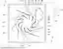
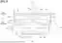
FIG. 1 is a diagram illustrating a cross-sectional view of a vehicle air-conditioning device according to a first embodiment, and is the diagram to assist in explaining an arrangement relationship of pre-swirl guides and an air guide casing, as well as a swirling flow caused by the pre-swirl guides.
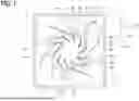
FIG. 2 is a cross-sectional view taken along line II-II in FIG. 1 of the vehicle air-conditioning device according to the first embodiment, and is a diagram to assist in explaining a positional relationship of the pre-swirl guides, blades, and an intake-hole forming portion that constitute the vehicle air-conditioning device.
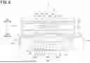
FIG. 3 is a diagram illustrating a vehicle air-conditioning device according to a second embodiment, and is a diagram to assist in explaining a positional relationship of pre-swirl guides, blades, and an intake-hole forming portion, and corresponds to the cross-sectional view shown in FIG. 2.
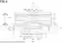
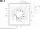
FIG. 4 is a diagram illustrating a cross-sectional configuration of a vehicle air-conditioning device according to a third embodiment, and is a cross-sectional view to assist in explaining an arrangement relationship of pre-swirl guides and an air guide casing, corresponding to FIG. 1.
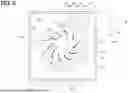
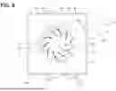
FIG. 5 is a diagram illustrating a cross-sectional configuration of a vehicle air-conditioning device according to a fourth embodiment, and is a cross-sectional view to assist in explaining an arrangement relationship of pre-swirl guides and an air guide casing, corresponding to FIG. 1.
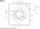
FIG. 6 is a diagram illustrating a cross-sectional configuration of a vehicle air-conditioning device according to a fifth embodiment, and is a cross-sectional view to assist in explaining an arrangement relationship of pre-swirl guides and an air guide casing, corresponding to FIG. 1.
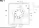
FIG. 7 is a diagram illustrating a vehicle air-conditioning device according to a sixth embodiment, and is a diagram to assist in explaining a positional relationship of pre-swirl guides, blades, and an intake-hole forming portion, and corresponds to the diagram shown in FIG. 2.
FIG. 8 is a diagram illustrating a vehicle air-conditioning device according to a seventh embodiment, and is a diagram to assist in explaining a positional relationship of pre-swirl guides, blades, and an intake-hole forming portion, and corresponds to the diagram shown in FIG. 2.
FIG. 9 is a diagram illustrating a cross-sectional view of a vehicle air-conditioning device according to an eighth embodiment, and is the diagram to assist in explaining an arrangement relationship of pre-swirl guides and an intake-hole forming portion, as well as a swirling flow caused by the pre-swirl guides.
FIG. 10 is a cross-sectional view taken along line X-X in FIG. 9 of the vehicle air-conditioning device according to the eighth embodiment, and is a cross-sectional view to assist in explaining a positional relationship of a guide unit, the pre-swirl guides, and a ring portion.
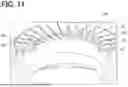
FIG. 11 is a cross-sectional view of a ceiling of a scroll casing in the vehicle air-conditioning device according to the eighth embodiment, cut along a virtual plane that includes an axis, and is a diagram to assist in explaining a positional relationship of the pre-swirl guides of the guide unit and the ring portion.
DETAILED DESCRIPTION
To begin with, examples of relevant techniques will be described.
A blower according to a comparative example include a casing having an intake hole that opens to one side in an axial direction, and a centrifugal fan disposed within the casing and having multiple blades arranged in a circumferential direction around an axis. As the centrifugal fan rotates about the axis, the centrifugal fan draws air into the casing through the intake hole on one axial side, pulling the air between adjacent blades among the multiple blades. The fan then expels this drawn-in air radially outward while rotating the centrifugal fan around the axis.
In the blower of the comparative example, as the centrifugal fan rotates, the centrifugal fan draws air into the casing through the intake hole on one axial side, pulling the air between adjacent blades among the multiple blades, and then expels this drawn-in air radially outward.
However, as described above, a direction of the air flow drawn between adjacent blades among the multiple blades through the intake hole on one axial side, and a direction of the air flow expelled radially outward between adjacent blades among the multiple blades, differ significantly.
Therefore, according to inventor's study, as described above, when air passes through the intake hole from one axial side and flows between adjacent blades among the multiple blades, turbulence occurs in the airflow, which may cause noise generation.
In contrast to the comparative example, according to a blower of the present disclosure, noise generation can be reduced.
According to one aspect of the present disclosure, a blower includes a casing having an intake hole which opens on one side in an axial direction. The axial direction is defined by an axis extending along a length of the casing. Within the casing, a centrifugal fan is housed. The centrifugal fan has blades arranged circumferentially about the axis. Each pair of adjacent blades defines an air flow path between them. The blades rotate in one direction about the axis, drawing air from one side through the intake hole into the air flow path, and discharge it outward in a radial direction with respect to the axis. Additionally, at least one guide is included, having a guide surface which directs air into the air flow path. This causes the air to swirl in the rotational direction while being drawn into the air flow path of the centrifugal fan. The at least one guide is configured such that a main stream of air flowing from the one side to another side in the axial direction and drawn into the air flow path is directed toward a direction of a main stream of air flowing through the air flow path.
According to this configuration, by providing one or more guides, the main direction of the airflow being drawn into the air flow path can be aligned with the main direction of the airflow passing through the air flow path.
As a result, the air guided by the at least one guide is smoothly drawn into the air flow path. As a result, abnormal noise that occurred when air was drawn into the air flow path can be reduced.
Hereinafter, embodiments of the present disclosure will be described with reference to the drawings. In the following embodiments, the same or equivalent parts are denoted by the same reference numerals as each other, and explanations will be provided to the same reference numerals for simplifying descriptions.
First Embodiment
FIG. 1 and FIG. 2 show an inside air conditioning unit 1 of a vehicle air-conditioning device according to a first embodiment. The inside air conditioning unit 1 of the present embodiment is installed inside a vehicle compartment, where the inside air conditioning unit intakes air from either inside or outside the vehicle compartment, adjusts a temperature of an intake air, and then discharges the adjusted air into the vehicle compartment.
More specifically, as shown in FIG. 1 and FIG. 2, the inside air conditioning unit 1 of the present embodiment includes an air guide casing 10A, a scroll casing 10B, a filter 20, a heat exchanger 30, a multi-blade fan 40, and pre-swirl guides 50.
FIG. 1 is a cross-sectional view of the air guide casing 10A cut along a plane orthogonal to an axis S, and FIG. 2 is a cross-sectional view taken along line II-II in FIG. 1. In FIG. 2, the axis S is a rotational centerline of the multi-blade fan 40, and am axial direction Za is a direction in which the axis S extends.
The air guide casing 10A is formed, for example, from a resin material or a metallic material, and defines an air flow path 11 that allows air to flow from one side to the other in the axial direction Za. The air flow path 11 is an air passage that guides an interior air of the vehicle compartment or an exterior air of the vehicle to an intake hole 12a of the scroll casing 10B.
The filter 20 is positioned within the air guide casing 10A and filters air flowing through the air flow path 11.
The heat exchanger 30 is a cooling heat exchanger positioned within the air guide casing 10A, which cools the air in the air flow path 11 by exchanging heat between the air that has passed through the filter 20 and refrigerant.
Additionally, the heat exchanger 30 may also be a heating heat exchanger that heats the air by exchanging heat between the air in the air flow path 11 that has passed through the filter 20 and the refrigerant. The heat exchanger 30 may utilize both a cooling heat exchanger and a heating heat exchanger.
The scroll casing 10B is positioned on the other side in the axial direction Za relative to the air guide casing 10A. The scroll casing 10B is formed, for example, from a resin material or a metal material. The scroll casing 10B houses a multi-blade fan 40.
The scroll casing 10B includes a ceiling 12 that is formed to cover the multi-blade fan 40 from one side in the axial direction Za. The ceiling 12 has the intake hole 12a that is open on one side in the axial direction Za.
The intake hole 12a is a ventilation passage that guides the airflow from the air flow path 11 of the air guide casing 10A to the multi-blade fan 40 within the scroll casing 10B. The intake hole 12a of the present embodiment is formed in a circular shape centered around the axis S. An intake-hole forming portion 13 of the ceiling 12, which constitutes the intake hole 12a, forms a bell mouth.
As shown in FIG. 2, the bell mouth is formed in an arc shape that is convex on one side in the axial direction Za when viewed in a cross-sectional view cut along a virtual plane containing the axis S. The bell mouth is provided around the entire circumference centered on the axis S.
The bell mouth plays a role in smoothly guiding air in the air flow path 11 of the air guide casing 10A from the outside in a radial direction Ka with respect to the axis S (i.e., a radially outer side) to the other side in the axial direction Za.
The scroll casing 10B has a blowing port 14 for discharging air blown out from the multi-blade fan 40.
The multi-blade fan 40 constitutes a centrifugal fan that, by rotating on one side of the radial direction Ra around the axis S, blows air outward in the radial direction Ka with respect to the axis S, which has flowed in from one side in the axial direction Za through the intake hole 12a.
As shown in FIG. 1, 2, the multi-blade fan 40 of the present embodiment is a turbo fan that includes blades 41, a main plate 42, and a ring 43.
The blades 41 are arranged at equal intervals in a circumferential direction centered around the axis S. Each of the blades 41 is formed such that, from an outer side to an inner side in the radial direction Ka centered around the axis S, they advance on one side in the radial direction Ra.
Between each pair of adjacent blades 41 among the blades 41, an air flow path 41a is provided. This air flow path 41a blows the air, which flows in through the intake hole 12a of the scroll casing 10B, outward in the radial direction Ka with respect to the axis S by centrifugal force.
The main plate 42 is positioned on the other side in the axial direction Za relative to the blades 41. The main plate 42 is formed in a disk shape centered around the axis S. The main plate 42 supports the blades 41 from the other side in the axial direction Za.
The ring 43 is positioned on one side in the axial direction Za relative to the blades 41. The ring 43 is formed in a ring shape centered around the axis S. The ring 43 supports the blades 41 from one side in the axial direction Za.
The blades 41, the main plate 42, and the ring 43 are formed from, for example, a resin material or a metal material. The multi-blade fan 40 of the present embodiment is configured to be driven by an electric motor (not shown) so that it can rotate in one direction Ra of rotation around the axis S.
Each of the pre-swirl guides 50 guides the air drawn into the air flow path 41a of the multi-blade fan 40, so that the air is drawn into the air flow path 41a of the multi-blade fan 40 while swirling in one direction Ra of rotation.
An outer region in the radial direction Ka around the respective axes S of the pre-swirl guides 50 is positioned on one side in the axial direction Za relative to the ceiling 12 of the scroll casing 10B. That is, the outer region of the pre-swirl guides 50 is positioned outside the intake hole 12a of the scroll casing 10B.
An inner region in the radial direction Ka around the respective axes S of the pre-swirl guides 50 is positioned radially inward (i.e., in the radial inward direction) relative to the intake hole 12a of the scroll casing 10B.
The pre-swirl guides 50 are arranged in the circumferential direction around the axes S, respectively. More specifically, the pre-swirl guides 50 are arranged at equal intervals in the circumferential direction around the axes S. The pre-swirl guides 50 are each formed to extend from an outer side to an inner side in the radial direction Ka around the axes S relative to the intake hole 12a.
The pre-swirl guides 50 are each formed to protrude from the ceiling 12 and the intake-hole forming portion 13. The pre-swirl guides 50 are each supported by the ceiling 12 and the intake-hole forming portion 13.
The pre-swirl guides 50 are each formed to extend on the other side Rb in a rotational direction as they move from the inner side to the outer side in the radial direction Ka around the axes S, respectively. The other side Rb in the rotational direction is an opposite side Ra of the rotational direction shown in FIG. 1.
The pre-swirl guides 50 each include lateral surfaces 51 and 52. The lateral surface 51 is a first guide surface formed on the one side Ra in the rotational direction of each of the pre-swirl guides 50.
The lateral surface 52 is a second guide surface formed on the other side Rb in the rotational direction of each of the pre-swirl guides 50. The lateral surfaces 51, 52 are each formed to extend on the other side Rb in a rotational direction as they move from the inner side to the outer side in the radial direction Ka around the axes S, respectively.
The pre-swirl guides 50 are each formed in a thin plate shape with a distance between the lateral surfaces 51 and 52 as the thickness. Inter-guide flow paths 53 are provided between each pair of adjacent pre-swirl guides 50 among the pre-swirl guides 50.
The lateral surfaces 51 and 52 of each of the pre-swirl guides 50 are guide surfaces that direct the air flowing through the inter-guide flow paths 53, so that the air passing through the intake hole 12a is drawn into the air flow paths 41a of the multi-blade fan 40 while swirling in the one side Ra in the rotational direction.
Hereinafter, for the sake of convenience in explanation, in each of the pre-swirl guides 50, a region positioned radially inward Ka around the axis S with respect to the intake-hole forming portion 13 is referred to as inner guide regions 50A.
Here, as shown in FIG. 2, the other end 50a in the axial direction Za of each of the inner guide regions 50A is provided at the same position in the axial direction Za as the other end 13a in the axial direction Za of the intake-hole forming portion 13.
The other end 50a in the axial direction Za of each of the inner guide regions 50A is positioned on one side Za in the axial direction with respect to a ceiling surface 12c of the ceiling 12 of the scroll casing 10B, which is located on the other side Za in the axial direction.
The other end (forming portion end) 13a of the intake-hole forming portion 13 is formed so as to surround the intake hole end (intake-hole end) 12b, which is positioned furthest on the other side Za in the axial direction (i.e., the furthest on the other side in the axial direction) of the intake hole 12a. Each of the pre-swirl guides 50 of the present embodiment is made of, for example, a resin material or a metal material.
More specifically, each of the pre-swirl guides 50 constitutes an integral component that is integrated with the scroll casing 10B. Each of the pre-swirl guides 50 is configured as a separate component from the scroll casing 10B. In the present embodiment, the scroll casing 10B, the multi-blade fan 40, and the pre-swirl guides 50 in the inside air conditioning unit 1 constitute a blower.
Next, the operation of the inside air conditioning unit 1 of the present embodiment will be described.
First, the multi-blade fan 40 is driven by an electric motor to rotate in one rotational direction Ra around the axis S. As a result, an airflow is generated in the air flow path 11 of the air guide casing 10A, flowing from one side to the other in the axial direction Za, as indicated by arrow F shown in FIG. 2.
At this time, the air in the air flow path 11 is filtered by the filter 20 as it passes through the filter 20. The air filtered by the filter 20 is cooled by the refrigerant as it passes through the heat exchanger 30.
The cooled air is guided by the lateral surfaces 51 and 52 of each of the pre-swirl guides 50 as it passes through the inter-guide flow paths 53 between two adjacent pre-swirl guides 50.
As a result, the air that has passed through the inter-guide flow paths 53 swirls in one rotational direction Ra, as indicated by arrow Q in FIG. 1, and is drawn into the air flow paths 41a of the multi-blade fan 40 through the intake hole 12a.
That is, the air that has passed through the inter-guide flow paths 53 passes through the intake hole 12a as a swirling flow and is smoothly drawn into the air flow paths 41a of the multi-blade fan 40.
The air drawn into each of these air flow paths 41a rotates in one rotational direction Ra and is expelled outward in the radial direction Ka centering around the axis S by centrifugal force.
The air expelled from these multi-blade fans 40 is collected by the scroll casing 10B and expelled from the blowing port 14 as indicated by arrow R shown in FIG. 1.
According to the present embodiment described above, the inside air conditioning unit 1 includes the scroll casing 10B that has the intake hole 12a opening on one side in the axial direction Za, with a direction extending along the axis S defined as the axial direction Za.
The multi-blade fan 40 is a centrifugal fan in which the blades 41 rotate in one rotational direction Ra around the axis S, drawing air in through the intake hole 12a from one side in the axial direction Za and expelling it outward in the radial direction Ka with respect to the axis S.
The blades 41 are housed within the scroll casing 10B and are arranged in the circumferential direction around the axis S. The air flow paths 41a are formed between each pair of adjacent blades 41 among the blades 41.
The inside air conditioning unit 1 includes the pre-swirling guides 50. The lateral surfaces 51 and 52 of each of the pre-swirling guides 50 guide the air being drawn into the air flow paths 41a such that the air swirls in one rotational direction Ra while being drawn into the air flow paths 41a.
Therefore, by providing the pre-swirling guides 50, the main flow direction of the air stream being drawn into the air flow paths 41a can be aligned more closely with the main flow direction of the air stream flowing through the air flow paths 41a.
As a result, the airflow that has passed through the intake hole 12a is smoothly drawn into the air flow paths 41a. Therefore, it is possible to prevent abnormal noise from occurring when the air that has passed through the intake hole 12a is drawn into the air flow paths 41a.
In the present embodiment, the other end 50a of each of the inner guide region 50A in the axial direction Za is provided at the same position as the other end 13a on the other side in the axial direction Za of the intake-hole forming portion 13.
Therefore, the pre-swirling guides 50 are capable of effectively guiding the air passing through each of the inter-guide flow paths 53 so that the lateral surfaces 51 and 52 cause the air to swirl in one rotational direction Ra.
Second Embodiment
In the above first embodiment, an example was described in which the other end 50a in the axial direction Za of each of the inner guide regions 50A is provided at the same position in the axial direction Za as the other end 13a in the axial direction Za of the intake-hole forming portion 13.
However, instead of this, in a second embodiment, as shown in FIG. 3, the other end 50a in the axial direction Za of each of the inner guide regions 50A is disposed on the other side in the axial direction Za relative to the other end 13a in the axial direction Za of the intake-hole forming portion 13.
The other end 13a of the intake-hole forming portion 13 is formed so as to surround an intake hole end 12b, which is positioned furthest on the other side in the axial direction Za of the intake hole 12a, as described above. In FIG. 3, the same reference numerals as those in FIG. 2 denote the same components, and their descriptions are omitted.
The other end 50a in the axial direction Za of each of the inner guide regions 50A is positioned on the other side in the axial direction Za with respect to the ceiling surface 12c of the ceiling 12 of the scroll casing 10B, which is located on the other side Za in the axial direction.
The other end 13a of the intake-hole forming portion 13 is positioned on the other side in the axial direction Za relative to the ceiling surface 12c.
According to the present embodiment described above, the other end 50a of each of the inner guide regions 50A in the axial direction Za is positioned on the other side in the axial direction Za relative to the other end 13a on the other side in the axial direction Za of the intake-hole forming portion 13, as described above.
Therefore, compared to the first embodiment, the other end 50a of each of the inner guide regions 50A in the axial direction Za can be positioned closer to the air flow paths 41a of the multi-blade fan 40.
Therefore, compared to the first embodiment, the lateral surfaces 51 and 52 are capable of guiding the air more effectively into the air flow paths 41a of the multi-blade fan 40 while causing the air to swirl in one rotational direction Ra as it is drawn into the air flow paths 41a.
Third Embodiment
In the first embodiment, an example was described in which the pre-swirling guides 50 are formed in a thin plate shape.
However, instead of this, a third embodiment in which pre-swirling guides 50 are each formed in a curved shape that is convex in one rotational direction Ra will be described with reference to FIG. 4. In FIG. 4, the same reference numerals as those in FIG. 1 indicate the same components, and their descriptions are omitted.
The pre-swirling guides 50 of the present embodiment each include lateral surfaces 51 and 52. The lateral surfaces 51 and 52 are guiding surfaces that guide the air passing through inter-guide flow paths 53 so that the air is drawn into the air flow paths 41a of the multi-blade fan 40 while swirling in one rotational direction Ra.
The lateral surface 51 is formed in an arc shape that is convex in one rotational direction Ra. The lateral surface 52 is formed in an arc shape that is concave in one rotational direction Ra.
In other words, the lateral surface 51 is formed in a circular arc shape that is convex toward one side Ra in the rotational direction in a cross-sectional view cut along an imaginary plane perpendicular to the axis S. The lateral surface 52 is formed in an arc shape that is concave in one rotational direction Ra in a cross-sectional view cut along an imaginary plane perpendicular to the axis S.
As a result, the lateral surfaces 51 and 52 are capable of appropriately guiding the air passing through the inter-guide flow paths 53 so that the air is drawn into the air flow paths 41a of the multi-blade fan 40 while swirling in one rotational direction Ra.
Fourth Embodiment
In the third embodiment described above, an example was explained where each of the pre-swirl guides 50 is formed in a curved shape that is convex in one rotational direction Ra.
However, in addition to this, in a fourth embodiment, as shown in FIG. 5, each of pre-swirl guides 50 is formed such that the thickness decreases from an outside to an inside in the radial direction Ka centered on the axis S.
The thickness refers to the dimension in a thickness direction, which is a direction connecting the lateral surfaces 51 and 52. That is, the thickness refers to a distance between the lateral surfaces 51 and 52. In FIG. 5, the same reference numerals as those in FIG. 1 indicate the same components, and their descriptions are omitted.
According to the present embodiment described above, the lateral surfaces 51 and 52 are capable of guiding the air more effectively into the air flow paths 41a of the multi-blade fan 40 while causing the air to swirl in one rotational direction Ra as it is drawn into the air flow paths 41a.
Fifth Embodiment
In the first embodiment described above, an example was explained where the pre-swirl guides 50 are arranged at equal intervals in the circumferential direction centered around the axis S. However, instead of this, in a fifth embodiment, as shown in FIG. 6, spacing between two of pre-swirl guides 50 is arranged to be uneven.
In the present embodiment, the pre-swirl guides 50 are arranged at intervals in the circumferential direction centered around the axis S, such that they form two or more different spacings. In FIG. 6, the same reference numerals as those in FIG. 1 denote the same components, and their descriptions are omitted.
Sixth Embodiment
In the first embodiment described above, an example in which ten pre-swirl guides 50 are provided in the inside air conditioning unit 1 was explained. However, the present invention is not limited to this. In a sixth embodiment, the number of pre-swirl guides 50 in the inside air conditioning unit 1 may be one or more. For example, as shown in FIG. 7, two pre-swirl guides 50 may be provided. In FIG. 7, the same reference numerals as those in FIG. 1 denote the same components, and their descriptions are omitted.
Seventh Embodiment
In a seventh embodiment, an example in which one end 54 in the axial direction Za of each of the pre-swirl guides 50 in the first embodiment is formed to extend toward one side in the axial direction Za as it progresses from an inside to an outside in the radial direction Ka with respect to the axis S will be described with reference to FIG. 8. In FIG. 8, the same reference numerals as those in FIG. 2 denote the same components, and their descriptions are omitted.
In the present embodiment, each of the pre-swirl guides 50 is arranged inside the air guide casing 10A. Each of the pre-swirl guides 50 is arranged outside the scroll casing 10B.
Each of the pre-swirl guides 50, similar to those in the first embodiment, includes lateral surfaces 51 and 52. The lateral surface 51 is a first guide surface formed on one side in the rotational direction Ra for each of the pre-swirl guides 50.
The lateral surface 52 is a second guide surface formed on the other side in the rotational direction Rb for each of the pre-swirl guides 50. The lateral surfaces 51 and 52 are each formed to extend toward the other side in the rotational direction Rb as they move outward from the inside in the radial direction Ka centered on the axis S.
Each of the pre-swirl guides 50 is positioned on one side in the axial direction Za relative to the ceiling 12 of the scroll casing 10B. Each of the pre-swirl guides 50 is positioned outward in the radial direction Ka centered on axis S from the intake-hole forming portion 13.
For the sake of convenience in the following description, an outer half region in the radial direction Ka centered on axis S for each of the pre-swirl guides 50 will be referred to as an outer half region 50b. For each of the pre-swirl guides 50, an inner half region in the radial direction Ka centered on axis S will be referred to as an inner half region 50c.
In FIG. 8, a boundary E indicates the center in the radial direction Ka centered on axis S for each of the pre-swirl guides 50, and it shows the boundary between the outer half region 50b and the inner half region 50c.
In the present embodiment, for each of the pre-swirl guides 50, a distance between an outer end in the radial direction Ka centered on axis S and the boundary E is equal to a distance between an inner end in the radial direction Ka centered on axis S and the boundary E.
In each of the pre-swirl guides 50 of the present embodiment, one end 54 in the axial direction Za (i.e., one end on the guide axial direction side) is formed to extend further in the axial direction Za as it moves from the inside to the outside in the radial direction Ka centered on axis S.
Therefore, dimensions of the lateral surfaces 51 and 52 in the axial direction Za increase as they extend from the inside to the outside in the radial direction Ka centered on axis S.
That is, in each of the pre-swirl guides 50, the one end 54 in the axial direction Za of the outer half region 50b is positioned further in one side of the axial direction Za compared to the one end 54 in the axial direction Za of the inner half region 50c. In FIG. 8, the same reference numerals as those in FIG. 2 denote the same components, and their descriptions are omitted.
As a result, compared to the first embodiment, the pre-swirl guides 50 in of the present embodiment are capable of guiding more air volume to be drawn into the multi-blade fan 40 while swirling to one side Ra in the rotational direction on the outer side in the radial direction Ka.
Here, within the air guide casing 10A, an air flow rate from one side in the axial direction Za to the intake hole 12a is greater on the inner side in the radial direction Ka compared to the outer side in the radial direction Ka centered on the axis S.
In each of the pre-swirl guides 50, the further the one end 54 is positioned toward the other side in the axial direction Za, the greater pressure loss of the air flow flowing into the intake hole 12a becomes.
On the other hand, in each of the pre-swirl guides 50, the one end 54 on the one side in the axial direction Za of the inner half region 50c is positioned further toward the other side in the axial direction Za compared to the one end 54 on the one side in the axial direction Za of the outer half region 50b.
Therefore, it is possible to preventively reduce an occurrence of pressure loss in the airflow flowing into the intake hole 12a due to the inner side in the radial direction Ka of each of the pre-swirl guides 50.
As a result, the pre-swirl guides 50 are capable of guiding a large volume of air to be drawn into the air flow paths 41a of the multi-blade fan 40 while reducing the occurrence of the pressure loss in the airflow and causing the air to swirl to one side in the rotational direction Ra.
Eighth Embodiment
In the first embodiment, the example was described in which each of the pre-swirl guides 50 constitutes an integrated structure that is integrated with the ceiling 12 of the scroll casing 10B. However, instead of this, an eighth embodiment in which each of pre-swirl guides 50 is independently configured with respect to a scroll casing 10B will be described with reference to FIGS. 9, 10, and 11.
In FIGS. 9 and 10, the same reference numerals as those in FIGS. 1 and 2 denote the same components, and a description of the same components will be omitted.
In the eighth embodiment, as shown in FIGS. 9, 10, and 11, the pre-swirl guides 50, together with a ring portion 151, constitute a guide unit 150.
As shown in FIG. 10, the ring portion 151 is formed in a ring shape centered around the axis S. The ring portion 151 is fitted into the intake-hole forming portion 13. The ring portion 151 is fixed to the ceiling 12 of the scroll casing 10B, for example, in a press-fitted state within the intake-hole forming portion 13.
The ring portion 151 may also be fixed to the ceiling 12 of the scroll casing 10B using an adhesive or similar material.
The pre-swirl guides 50 are formed to protrude inward in the radial direction Ka from the ring portion 151, centered around the axis S. Therefore, each of the pre-swirl guides 50 is arranged inward in the radial direction Ka with respect to the intake-hole forming portion 13, centered around the axis S.
The pre-swirl guides 50 of the present embodiment form the guide unit 150, which is an integrated structure unified with the ring portion 151. The guide unit 150 is configured independently from the scroll casing 10B.
In other words, the pre-swirl guides 50 are configured independently from the scroll casing 10B. In other words, the pre-swirl guides 50 are configured as separate components from the scroll casing 10B.
According to the present embodiment described above, each of the pre-swirl guides 50 is positioned radially inward in the radial direction Ka with respect to the intake-hole forming portion 13 around the axis S by the guide unit 150.
Each of the pre-swirl guides 50 includes the lateral surfaces 51 and 52. The lateral surfaces 51 and 52 are each formed to extend toward the other side in the rotational direction Rb as they move outward from the inside in the radial direction Ka centered on the axis S.
Thus, each of the lateral surfaces 51 and 52 of the pre-swirl guides 50 is capable of guiding the air passing through each of the inter-guide flow paths 53 within the intake hole 12a so that the air swirls in one rotational direction Ra.
Other Embodiments
(1) In the above first to eighth embodiments, examples in which the blower of the present disclosure is applied to an inside air conditioning unit 1 for a vehicle have been described. However, the blower of the present disclosure is not limited to this and may be applied to air conditioning equipment other than the inside air conditioning unit 1.
(2) In the above first to eighth embodiments, an example using a turbo fan as the multi-blade fan 40 has been described. However, instead of a turbo fan, various centrifugal fans such as a sirocco fan may be used as the multi-blade fan 40.
(3) In the above first to eighth embodiments, an example in which the intake-hole forming portion 13 of the scroll casing 10B constitutes a bell mouth has been described. However, the intake-hole forming portion 13 of the scroll casing 10B does not necessarily have to constitute a bell mouth.
(4) While the present disclosure has been described with reference to embodiments thereof, it is to be understood that the disclosure is not limited to the embodiments and constructions. To the contrary, the present disclosure is intended to cover various modification and equivalent arrangements. In addition, while the various elements are shown in various combinations and configurations, which are exemplary, other combinations and configurations, including more, less or only a single element, are also within the spirit and scope of the present disclosure.
Claims
What is claimed is:1. A blower comprising:
a casing having an intake hole opening on one side in an axial direction in which an axis extends is the axial direction;
a centrifugal fan housed within the casing, the centrifugal fan including blades arranged in a circumferential direction about the axis, each pair of adjacent blades defining an air flow path therebetween, and the blades rotating in one rotational direction about the axis for drawing air from the one side in the axial direction through the intake hole into the air flow path and discharging the drawn air outward in a radial direction with respect to the axis; and
at least one guide having a guide surface directing air into the air flow path such that the air swirls in the one rotational direction while being drawn into the air flow path of the centrifugal fan, wherein
the at least one guide is configured such that a main stream of air flowing from the one side to another side in the axial direction and drawn into the air flow path is directed toward a direction of a main stream of air flowing through the air flow path.
2. The blower according to claim 1, wherein
the guide surface is formed such that the guide surface is inclined in a direction opposite to the one rotational direction as the guide surface extends from an inner side to an outer side in the radial direction with respect to the axis.
3. The blower according to claim 2, wherein
the guide surface is a first guide surface provided on a side in the one rotational direction of the at least one guide,
the at least one guide has a second guide surface provided on another side in the opposite rotational direction, and
the second guide surface is formed such that the second guide surface is inclined in the direction opposite to the rotational direction as the second guide surface extends from the inner side to the outer side in the radial direction with respect to the axis, and guiding the air to be drawn into the air flow path of the centrifugal fan such that the air swirls in the one rotational direction.
4. The blower according to claim 3, wherein
the first guide surface is formed in an arcuate shape being convex in the one rotational direction, and
the second guide surface is formed in an arcuate shape being concave in the one rotational direction.
5. The blower according to claim 3, wherein
a distance between the first guide surface and the second guide surface is a thickness, and
the thickness of the at least one guide decreases from the outer side to the inner side in the radial direction with respect to the axis.
6. The blower according to claim 1, wherein
the at least one guide is one of guides arranged at intervals in the circumferential direction about the axis.
7. The blower according to claim 6, wherein
the guides are arranged at equal intervals in the circumferential direction.
8. The blower according to claim 1, wherein
the casing has an intake-hole forming portion defining the intake hole, and
the at least one guide is positioned inward of the intake-hole forming portion in the radial direction with respect to the axis.
9. The blower according to claim 1, wherein
the casing has an intake-hole forming portion defining the air intake hole,
the intake-hole forming portion has a forming portion end surrounding an intake-hole end positioned furthest on another side in the axial direction of the intake hole,
an inner guide region is a region of the at least one guide positioned inward of the intake-hole forming portion in the radial direction with respect to the axis, and
another end portion of the inner guide region in the axial direction is positioned on another side in the axial direction relative to the forming portion end.
10. The blower according to claim 1, wherein
the at least one guide is positioned outside the casing,
a guide end portion is an end portion of the at least one guide on the one side in the axial direction,
an outer half region is a region of the at least one guide positioned outside in the radial direction with respect to the axis,
an inner half region is a region of the at least one guide positioned inside relative to the outer half region in the radial direction with respect to the axis, and
the guide end portion in the outer half region is positioned further on the one side in the axial direction compared to the guide end portion in the inner half region.
11. The blower according to claim 1, wherein
the at least one guide is provided separately from the casing.
Images & Drawings included:

Sources:
- United States Patent and Trademark Office - verify current appl. status at the USPTO↗
Similar patent applications:
- » 20110250049
Airflow from a blower with one or more adjustable guide vanes that are affixed to the blower at one or more pivot points located in an outlet of the blower - » 20190226491
Blower device and blower system equipped with blower device - » 20090047133
IMPELLER BLADE FOR CENTRIFUGAL BLOWER, BLADE-SUPPORTING ROTATOR, IMPELLER FOR CENTRIFUGAL BLOWER, AND METHOD FOR MANUFACTURING IMPELLER FOR CENTRIFUGAL BLOWER - » 20110250048
Airflow from a blower with one or more adjustable guide vanes that are affixed to the blower at one or more pivot points located in an outlet of the blower - » 20140060542
BLOWER FILTER DEVICE OF A BLOWER FILTER SYSTEM AS WELL AS BLOWER FILTER SYSTEM - » 20150360060
CARRYING SYSTEM FOR A BLOWER FILTER DEVICE, BLOWER FILTER DEVICE AS WELL AS BLOWER FILTER SYSTEM - » 10703514
Blower having a blower tube incorporating a reduction device for reducing the clear flow cross section of said blower tube at idle operation - » 18861587
Blower housing, blower wiring structure, and blower - » 20110250047
Airflow from a blower with one or more adjustable guide vanes that are affixed to the blower at one or more pivot points located in an outlet of the blower - » 20200351986
Blower system, blower and method for operating and for installing a blower
Recent applications in this class:
- » 20250320880 2025-10-16
Centrifugal Air Blower - » 20250250989 2025-08-07
DIFFUSER PIPE FOR AN AIRCRAFT PROPULSION SYSTEM - » 20250243875 2025-07-31
CONTROLLED AREA PROGRESSION DIFFUSER - » 20250215892 2025-07-03
COMPRESSOR COVER, CENTRIFUGAL COMPRESSOR, TURBOCHARGER, METHOD FOR MANUFACTURING COMPRESSOR COVER, AND DIFFUSER FOR CENTRIFUGAL COMPRESSOR - » 20250207608 2025-06-26
APPARATUS FOR REDUCING AIR TURBULENCE IN A FAN CHASSIS - » 20250084868 2025-03-13
BLOWER - » 20250084867 2025-03-13
FAN HAVING A STEP DIFFUSER - » 20250059982 2025-02-20
TURBO MACHINE AND METHOD OF MANUFACTURING - » 20240426318 2024-12-26
Refrigerant compressor with impeller having slotted shroud - » 20240410391 2024-12-12
INFLATOR HAVING COMBINED CUTWATER AND INTAKE/EXHAUST PORT