STADIUM SEAT STABILIZATION SYSTEM
US20260013635A1
2026-01-15
19/266,390
2025-07-11
Smart Summary: A stadium seat stabilization system helps keep seats secure in place. It uses a rail with a front and rear overhang to support the seats. A support member attaches the seat to the rail and wraps around the back. Inside this support, there's a pocket that holds a moveable insert with a fastener. When the fastener is adjusted, it pushes the support member up and presses down on the rail, making sure the seat stays firmly in position. 🚀 TL;DR
Abstract:
A stadium fitting stabilization system includes a rail having an upper surface, a front overhang, and a rear overhang. A support member secures a fitting to the rail and includes a return portion that engages and wraps around the rear overhang and an intermediate portion that extends from the return portion along the upper surface and at least partially beyond the front overhang. The intermediate portion includes a pocket having an aperture communicating with the upper surface. A moveable insert includes a fastener and is received in the pocket and engages the upper surface. Advancement or rotation of the fastener translates the moveable insert relative to the pocket, causing the moveable insert to exert an upward force on the support member and a downward force on the rail through the aperture, urging the return portion toward engagement with the rear overhang and securing the support member against the rail.
Applicant:
Interested in similar patents?
Get notified when new applications in this technology area are published.
Classification:
A47C1/121 » CPC main
Chairs adapted for special purposes; Theatre, auditorium, or similar chairs having tipping-up seats
A47C7/56 » CPC further
Parts, details, or accessories of chairs or stools Parts or details of tipping-up chairs, e.g. of theatre chairs
Description
CROSS REFERENCE TO RELATED APPLICATION
The present application claims the filing benefits of GB patent application No. GB2410308.7, filed Jul. 15, 2024, which is hereby incorporated herein by reference in its entirety.
FIELD OF THE INVENTION
The present specification relates to stadium seat stablisation systems, particularly for the stabilization and/or securement of seats, seat parts and other stadium fixings to a rail.
BACKGROUND OF THE INVENTION
Seating systems in stadiums, arenas, and other entertainment venues are typically arranged in rows, either on the floor or in a tiered or stepped format. A common method of mounting the seats in a ganged format in rows is to assemble the seating onto a structural elongate section or rail. These seating rails can be constructed from a variety of materials such as hollow steel sections, aluminium extrusions, or even composite materials like glass-reinforced plastics. The rails are usually attached to the building on support legs provided at intervals, and the seats attached directly to the seating rail. Both the support legs and the seat connections to the rail must be secure to eliminate movement.
Various seating rails and seats adapted to fit the profiles of these seating rails have been adopted. Seating rails are expensive to produce and install, and being constructed from very durable materials, they typically outlast the seating affixed to them. The seats themselves are typically manufactured from plastics, wooden preforms, and upholstery, which are subject to high degrees of degradation, especially in outdoor environments. Therefore, they may need to be replaced well before the seating rail, possibly several times over many years.
One such rail and seating system is disclosed in U.S. Pat. No. 7,073,858 (which is hereby incorporated herein by reference in its entirety). Referring to FIG. 3 of the '858 patent, the rail includes an upper portion having an upper surface 16, front overhang or nose 15 and a rear overhang 17. Referring to FIG. 8 of the '858 patent, the support member 61 of the seat features a clamp portion 68 and return portion 69 which hooks over the rear overhang 17 of the rail, while an intermediate portion 70 of the support member rests on the upper surface 16 of the rail and a forwardly directed portion 71 of the support member extends beyond the front overhang or nose 15. A toggle fastener 72 attached to the forwardly directed portion 71 and engages with the underside of the front overhang or nose 15, securing the support to the rail.
Unfortunately, if the profile of the support member 61 does not closely match the corresponding profile of the rail, movement can occur between the support member and rail. This can occur for various reasons, the chief reason being that the support member is typically fabricated from glass reinforced polymer. This material will often shrink anisotropically, depending on the orientation of the glass strands in the plastic material, the orientation of the glass strands itself depending on how the material fills the mould. Though less of a factor, the moulds for the support member and the extrusion die for the rail 12 also can be subject to wear. Therefore, the tolerance of both parts, though particularly the support member 61, can vary, resulting in a mismatch between these ideally corresponding parts, making it very difficult to maintain a close or interference fit between the seating rail and the resulting fit-up, resulting in a loose fit. Unfortunately, no amount of pressure applied by the toggle fastener can correct such a mismatch between the curved clamp portion of the support member and the rear overhang of the rail.
SUMMARY OF THE INVENTION
An object of this invention is to provide a system which improves the securement of a seat to a rail and reduce or eliminate movement between the seat and rail.
According to an aspect of the present invention, a stadium fitting stabilization system includes a rail having an upper surface, a front overhang, and a rear overhang. A support member is configured to secure a fitting to the rail, such as a seat assembly or an armrest. The support member includes a return portion that engages and wraps at least partially around the rear overhang of the rail and an intermediate portion that extends from the return portion along the upper surface of the rail and at least partially beyond the front overhang. The intermediate portion includes a pocket having an aperture communicating with the upper surface of the rail. A moveable insert is configured to be received in the pocket and engage the upper surface of the rail. The moveable insert includes a fastener. With the moveable insert received in the pocket and engaging the upper surface of the rail, advancement or rotation of the fastener translates the moveable insert relative to the pocket, causing the moveable insert to exert an upward force on the support member and a downward force on the rail through the aperture, urging the return portion toward engagement with the rear overhang of the rail and securing the support member against the rail.
The terms forward and rear, and similar cognate terms, are used herein with reference to a seat positioned on a rail, the seat back being a rearward part of the seat.
These and other objects, advantages, purposes and features of the present invention will become apparent upon review of the following specification in conjunction with the drawings.
BRIEF DESCRIPTION OF THE DRAWINGS
The invention will now be described, by way of example, with reference to the drawings, of which:
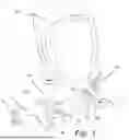
FIG. 1 is a perspective view of an embodiment of the seat stabilization system;
FIG. 2 is a perspective view of a detail of the seat stabilization system;
FIG. 3 is a sectional view of a detail of the seat stabilization system;
FIG. 4 is a perspective view of another embodiment of the seat stabilization system;
FIG. 5 is a perspective view of a detail of the seat stabilization system of FIG. 4;
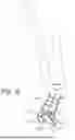
FIG. 6 is a side elevation of the seat stabilization system of FIG. 4;
FIG. 7 is a sectional view of an embodiment of an arm rest stabilization system;
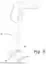
FIG. 8 is a perspective view of the arm rest stabilization system of FIG. 7; and
FIG. 9 is a partially exploded perspective view of the arm rest stabilization system of FIG. 7.
DESCRIPTION OF THE PREFERRED EMBODIMENTS
Referring to FIG. 1, a seat 10 is secured to a rail 12 by support member 61. The rail 12 may be as disclosed in U.S. Pat. No. 7,073,858 (which is hereby incorporated herein by reference in its entirety), and discussed above, comprising an upper portion having an upper surface 16, front overhang or nose 15 and a rear overhang 17, formed from extruded aluminium.
The leg or support member 61 of the seat features a clamp portion 68 and return portion 69 which hooks over the rear overhang 17 of the rail, while an intermediate portion 70 of the support member rests on the upper surface 16 of the rail and a forwardly directed portion 71 of the support member extends beyond the front overhang or nose 15. It also includes a toggle fastener 72 attached to the forwardly directed portion 71 and engages with the underside of the front overhang or nose 15, securing the support to the rail. In these respects, it is similar to the seat disclosed in U.S. Pat. No. 7,073,858.
The support member 61 also includes a wedge 20 which fits in a pocket 22 in the support member 61. Referring to FIGS. 2 and 3, the pocket 22 is generally defined by the upper wall 26 of the intermediate portion 70, lateral side walls 24, 25, and the central web 29 that connects the upper wall 26 and the lower wall 27 of the support member 61. The lower wall 27 has an aperture 30 such that the pocket has unobstructed communication with the upper surface 16 of the rail 12.
The central web 29 is the only vertical structure of the intermediate portion 70 of the support member 61 in this location, thus the pocket is open on one side, allowing insertion of the wedge 20. The pocket 22 includes downwardly extending lead-in ribs 28 on the upper wall 26, these ribs 28 being tapered from the central web 29 to the lateral mouth of the pocket 22 (i.e. the ribs 28 depend more at towards the central web 29 than at the mouth of the pocket 22).
The wedge 20 is tapered so that the face inserted into the pocket is shorter than the opposite face; in particular, the upper and lower surfaces of the wedge 20 narrow towards the inserted end (the side faces are ideally parallel and not tapered). The wedge 20 has a slot elongated in a substantially vertical direction which accepts a self-tapping screw, while the central web 29 of the pocket 22 includes a boss 31 having a bore aligned to accept this self-tapping screw as it extends through the wedge 20. Turning the self-tapping screw 21 then cuts a thread into the boss 31 and draws the wedge 20 into the pocket 22 towards the central web 29, the head of the self-tapping screw 21 abutting the outside of the elongate slot.
As the wedge 20 is urged into the pocket 22, the taper of the wedge 20 and the ribs 28 are such that the wedge 20 is forced downward, the lower surface of the wedge 20 moving downwardly through the aperture 30 in the lower wall 27 of the intermediate portion 70 of the support member 61. The elongate slot accommodates this movement, so that the self-tapping screw rides upward relative to the wedge 20 even as it urges the wedge 20 into the pocket 22. Thus, when the support member 61 is located on the rail 12, insertion of the wedge 20 and its advancement towards the central web 29 by turning the self-tapping screw 21 forces the lower surface of the wedge 20 against the upper surface 16 of the rail 12, the wedge 20 exerting an upward force on the support member 61 and a downward force on the upper surface 16 of the rail 12, raises the bottom of the return portion 69 of the support member 61 against the rear overhang 17 of the rail 12, securing the position of the support member 61 against the rail 12. This securement takes place even if there is play between the support member 61 (and in particular, the return portion 69 of the support member 61 and the rear overhang 17 of the rail 12). Thus, the provision of the wedge 20 and corresponding pocket 22 in the support member 61 allows the seat to be fully secured even when the tolerance of the support member 61 is not ideal.
Ideally, the wedge 20 and pocket 22 are provided on each support member 61 of a seat 10, and each pocket 22 opens towards the inside of the seat 10, though of course the pocket 22 could open outwardly, and a benefit would be derived from using a pocket 22 and wedge 20 even on one support member 61 of the seat 10.
Referring to FIGS. 4 to 6, rather than a wedge 20, a cammed insert 42 is insertable into the pocket 22 of the support member 61 in the intermediate portion 70. As in the previous embodiment, the pocket 22 is defined by the upper wall 26 and side walls 24, 25 of the support member 61, and the lower wall 27 of the support member 61 includes an aperture communicated with the upper surface 16 of the rail 12.
The cammed insert 42 is generally cylindrical in form, and includes an eccentric through bore through which a self-tapping screw 43 extends. The central web 29 includes a boss 44 with a bore to accept the self-tapping screw 43. As the self-tapping screw 43 is rotated, it cuts a thread in the bore of the boss and the head of the self-tapping screw 43 engages the through bore of the cammed insert 42, drawing the cammed insert 42 inwardly into the pocket 22. The outer face of the cammed insert 42 includes a slot 45 which allows the cammed insert 42 to be rotated.
Since the bore of the cammed insert 42 is eccentrically aligned, rotation of the cammed insert 42 causes the perimeter of the cammed insert 42 adjacent to the upper surface 16 of the support member 61 to first approach and then abut and press against the upper surface 16 in the manner of a projecting lobe of a cam, the cammed insert 42 exerting a downward force on the upper surface 16, and a corresponding upward pressure (via the self-tapping screw 43) on the support member 61. Thus, by driving the cammed insert 42 into the pocket 22 of the support member 61, the cammed insert 42 raises the bottom of the return portion 69 of the support member 61 against the rear overhang 17 of the rail 12, securing the position of the support member 61 against the rail 12 even where there is play between the support member 61 (and in particular, the return portion 69 of the support member 61 and the rear overhang 17 of the rail 12). As for the previous embodiment, the provision of the cammed insert 42 and corresponding pocket 22 in the support member 61 allows the seat to be fully secured even when the tolerance of the support member 61 is not ideal.
It will be realized that the cammed insert 42 could be formed in similar shapes, such as an elliptical or oval cross section, to exert a force when rotated. The rotation of the cammed insert 42 could be achieved by other means, for example more than one slot could be provided on the face of the cammed insert 42 so that some form of corresponding key could be used to conveniently turn the cammed insert, or the boss 44 and the cammed insert could feature cooperating surfaces which are both inclined to the axis of the screw, urging the cammed insert 42 to rotate when the face of the cammed insert 42 contacts the face of the boss 44.
In both the embodiments described and shown in FIGS. 1 to 5, an adjustment and securement member is inserted into a pocket 22 in the support member 61 from a generally transverse direction to the main axis of the support member, and generally opposing surfaces of that member exert a force up substantially upward on the support member, and substantially downward on the upper surface of the rail in order to raise the bottom part of the return portion of the support member against the rail. This principle can also be applied to other fittings that attach to the rail 12. Further, the direction in which the adjustment and securement member does not have to be inserted in a transverse direction.
Referring to FIGS. 7 to 9, an arm rest 50 includes a support portion 51, which, in a similar manner to the support member 61 of the previous embodiments, features a clamp portion 68 and return portion 69 which hooks over the rear overhang 17 of the rail, and an intermediate portion 70 of the support portion 51 rests on the upper surface 16 of the rail and a forwardly directed portion 71 of the support portion 51 extends beyond the front overhang or nose 15. A clamp 72 is attached to the forwardly directed portion 71 and engages with the underside of the front overhang or nose 15, to generally securing the support to the rail.
The arm rest 50 includes a lower cavity 52 whose upper extent is defined by an internal wall 54, which is generally transversely aligned to the main axis of the upright portion of the arm rest 50. The intermediate portion 70 of the support portion 51 includes an aperture 30 which openly communicates with the upper surface 16 of the rail 12. A shaped wedge 55 is located in the lower cavity 52, and the front wall 64 of the arm rest 50 includes a hole 56 having a threaded insert 63.
When a bolt 62 is advanced rearwardly through the hole 56 and threaded insert 63 into the lower cavity 52, the end of the bolt 62 abuts the shaped wedge 55 and urges it in a rearward direction. The internal wall 54 is less inclined from the horizontal than upper surface 16 of the rail 12, so that the distance between the internal wall 54 and upper surface 16 is greater towards the front of the arm rest 50 than towards the rear of the arm rest 50. The shaped wedge 55 tapers so that the narrower end is oriented towards the rear of the arm rest 50. Therefore, as the bolt 62 urges the shaped wedge 55 rearward, the lower surface of the shaped wedge 55 comes to bear through the aperture 30 of the support portion 51 against the upper surface 16 of the rail 12, and the shaped wedge 55 exerts an upward force on the support portion 51 and a downward force on the rail 12, raising the bottom of the return portion 69 of the support portion 51 against the rear overhang 17 of the rail 12, securing the position of the support portion 51 against the rail 12. As in the previous embodiments, this securement takes place even if there is play between the support portion 51 (and in particular, the return portion 69 of the support portion 51 and the rear overhang 17 of the rail 12). Thus, the provision of the shaped wedge 55 and corresponding lower cavity 52 in the support portion 51 of the arm rest 50 allows the arm rest to be fully secured even when the tolerance of the support portion 51 is not ideal.
The essence of these embodiments is that a moveable insert is translated in a cavity in the support portion of a fitting to the profiled rail, this translation causing a surface of the moveable insert to be urged against the rail through an aperture in the cavity, lifting the fitting upward relative to the rail and so raising the return portion of the support portion to bear securely against the rear overhang of the rail, securing the fitting against the rail even when the conformity between the support portion and the rail does not have an ideal tolerance.
The screws of bolts used to urge the inserts (whether a wedge or a cammed insert) may be adapted to be rotated either by a conventional screwdriver or by a hex key, or by some other driving means.
In this specification an apparatus/method/product “comprising” certain features is intended to be interpreted as meaning that it includes those features, but that it does not exclude the presence of other features.
Many variations are possible without departing from the scope of the present invention as defined in the appended claims.
Claims
1. A stadium fitting stabilization system, the stadium fitting stabilization system comprising:
a rail having an upper surface, a front overhang, and a rear overhang;
a support member for securing a fitting to the rail, wherein the support member comprises (i) a return portion that engages and wraps at least partially around the rear overhang of the rail and (ii) an intermediate portion that extends from the return portion along the upper surface of the rail and at least partially beyond the front overhang;
wherein the intermediate portion comprises a pocket having an aperture communicating with the upper surface of the rail;
a moveable insert configured to be received in the pocket and engage the upper surface of the rail, wherein the moveable insert includes a fastener; and
wherein, with the moveable insert received in the pocket and engaging the upper surface of the rail, advancement or rotation of the fastener translates the moveable insert relative to the pocket, causing the moveable insert to exert an upward force on the support member and a downward force on the rail through the aperture, urging the return portion toward engagement with the rear overhang of the rail and securing the support member against the rail.
2. The stadium fitting stabilization system of claim 1, wherein the moveable insert comprises a wedge having a tapered shape.
3. The stadium fitting stabilization system of claim 2, wherein the wedge includes an elongated slot that receives the fastener.
4. The stadium fitting stabilization system of claim 2, wherein the pocket includes an inclined upper surface.
5. The stadium fitting stabilization system of claim 1, wherein the moveable insert comprises a cammed insert having a generally cylindrical form with an eccentric through bore that receives the fastener, and wherein rotation of the fastener causes the cammed insert to rotate and press against the upper surface of the rail.
6. The stadium fitting stabilization system of claim 5, wherein the cammed insert and the pocket include inclined faces that interact during advancement or rotation of the fastener to cause the cammed insert to rotate and exert the downward force on the rail.
7. The stadium fitting stabilization system of claim 1, wherein the pocket comprises a lower cavity having an internal wall and an aperture communicating with the upper surface of the rail, and wherein the moveable insert comprises a shaped wedge received in the lower cavity, and wherein the shaped wedge tapers towards the rear overhang, and wherein the shaped wedge, during advancement or rotation of the fastener, is urged rearward by the fastener, such that the shaped wedge exerts the upward force on the support member and the downward force on the rail through the aperture.
8. The stadium fitting stabilization system of claim 7, wherein the fastener comprises a bolt that extends through a hole in a front wall of the support member and, during advancement or rotation of the fastener, threads into an insert within the lower cavity.
9. The stadium fitting stabilization system of claim 1, wherein the fitting comprises a seat assembly.
10. The stadium fitting stabilization system of claim 1, wherein the fitting comprises an armrest.
11. A stadium fitting, the stadium fitting comprising:
a fitting member;
a support member configured to secure the fitting member to a rail, wherein the rail comprises an upper surface, a front overhang, and a rear overhang;
wherein the support member comprises a return portion and an intermediate portion;
wherein, with the support member securing the fitting member to the rail, (i) the return portion engages and wraps at least partially around the rear overhang of the rail and (ii) the intermediate portion extends from the return portion along the upper surface of the rail and at least partially beyond the front overhang;
wherein the intermediate portion comprises a pocket having an aperture, and wherein, with the support member securing the fitting member to the rail, the aperture communicates with the upper surface of the rail;
a moveable insert that includes a fastener, wherein the moveable insert, with the support member securing the fitting member to the rail, is received in the pocket and engages the upper surface of the rail; and
wherein, with the support member securing the fitting member to the rail, and with the moveable insert received in the pocket and engaging the upper surface of the rail, advancement or rotation of the fastener translates the moveable insert relative to the pocket, causing the moveable insert to exert an upward force on the support member and a downward force on the rail through the aperture, urging the return portion toward engagement with the rear overhang of the rail and securing the support member against the rail.
12. The stadium fitting of claim 11, wherein the moveable insert comprises a wedge having a tapered shape.
13. The stadium fitting of claim 12, wherein the wedge includes an elongated slot that receives the fastener.
14. The stadium fitting of claim 12, wherein the pocket includes an inclined upper surface.
15. The stadium fitting of claim 11, wherein the moveable insert comprises a cammed insert having a generally cylindrical form with an eccentric through bore that receives the fastener, and wherein rotation of the fastener causes the cammed insert to rotate and press against the upper surface of the rail.
16. The stadium fitting of claim 15, wherein the cammed insert and the pocket include inclined faces that interact during advancement or rotation of the fastener to cause the cammed insert to rotate and exert the downward force on the rail.
17. The stadium fitting of claim 11, wherein the pocket comprises a lower cavity having an internal wall and an aperture communicating with the upper surface of the rail, and wherein the moveable insert comprises a shaped wedge received in the lower cavity, and wherein the shaped wedge tapers towards the rear overhang, and wherein the shaped wedge, during advancement or rotation of the fastener, is urged rearward by the fastener, such that the shaped wedge exerts the upward force on the support member and the downward force on the rail through the aperture.
18. The stadium fitting of claim 17, wherein the fastener comprises a bolt that extends through a hole in a front wall of the support member and, during advancement or rotation of the fastener, threads into an insert within the lower cavity.
19. The stadium fitting of claim 11, wherein the fitting member comprises a seat assembly.
20. The stadium fitting of claim 11, wherein the fitting member comprises an armrest.
Images & Drawings included:


Sources:
- United States Patent and Trademark Office - verify current appl. status at the USPTO↗
Recent applications in this class:
- » 20250366616 2025-12-04
THEATER CHAIR OR SEAT WITH A FLIP-UP/FLIP-DOWN SEAT MEMBER, A RECLINING BACK MEMBER, AND AN AUTOMATIC RETURN - » 20250331638 2025-10-30
SEATING SYSTEM - » 20250311849 2025-10-09
SEATING SYSTEM - » 20240365981 2024-11-07
Polyvalent folding chair with counterweight - » 20240335040 2024-10-10
PIVOT STRUCTURE FOR PIVOTING SEAT - » 20240016294 2024-01-18
Seat connection mechanism using metallic and polymer components - » 20240008650 2024-01-11
Chair with molded panel - » 20230371691 2023-11-23
Fence seat device - » 20210153655 2021-05-27
Folding chairs - » 20210112984 2021-04-22
Reversible chair