HEADREST ROTATING MECHANISM, HEADREST STRUCTURE FOR SEAT UNIT, AND SEAT UNIT
US20260013636A1
2026-01-15
19/336,486
2025-09-22
Smart Summary: A mechanism allows a headrest above a seat's backrest to rotate forward or backward. It includes a device that connects the headrest to the backrest and an electric motor that moves this device. The headrest is attached to two side plates, while the backrest is connected to another set of side plates. These plates are linked together with a joint that lets them move. This design also includes a specific headrest structure and a complete seat unit. 🚀 TL;DR
Abstract:
The present disclosure relates to a headrest rotating mechanism, configured to rotate a headrest disposed above a backrest of a seat unit relative to the backrest forward or backward, the headrest rotating mechanism including a headrest rotating device (3) and an actuating motor (4) configured to drive the headrest rotating device (3) to move, where the headrest rotating device (3) includes a pair of first side plates (31) configured to attach the headrest and a pair of second side plates (32) configured to attach the backrest, the first side plates (31) and the second side plates (32) are movably connected via a headrest joint (33). Additionally, the present disclosure further relates to a headrest structure for a seat unit and a seat unit.
Inventors:
- Tao Wang 13 🇨🇳 Suzhou, China
- Xiaohong Li 32 🇨🇳 Suzhou, China
- Haibo Wang 13 🇨🇳 Suzhou, China
- Saijun Cai 9 🇨🇳 Suzhou, China
Applicant:
Interested in similar patents?
Get notified when new applications in this technology area are published.
Classification:
A47C7/38 » CPC main
Parts, details, or accessories of chairs or stools; Support for the head or the back for the head
Description
CROSS REFERENCE TO RELATED APPLICATIONS
The present disclosure is a Continuation Application of PCT Application No. PCT/CN2024/080427 filed on Mar. 7, 2024, which claims priority of Chinese Patent Applications No. 2023103007590 filed on Mar. 24, 2023 before CNIPA. All the above are hereby incorporated by reference in their entirety as part of the present disclosure.
TECHNICAL FIELD
The present disclosure relates to a headrest rotating mechanism, and a headrest structure for seat unit. Additionally, the present disclosure further relates to a seat unit including the headrest structure.
BACKGROUND
A variety of movable chairs are known in the prior art. To improve the comfort of a user, a movable headrest structure is usually mounted above a backrest portion. However, some defects often exist in existing headrest structures, for example, in seat models where the headrest and the backrest are jointly covered within a flexible covering portion, the covering portion between the headrest and the backrest connection portion is overstretched due to pivoting of the headrest, because the folding gap is too large, the elasticity requirement for the backrest covering portion material is too high, which easily causes creases and wear of the covering portion, and also increases material cost; the headrest parts are too long, for seat models that also need to carry a lumbar pillow, it is difficult to compress the backrest height; the connection relationship between the electric driver and the headrest bracket is improper, resulting in poor adjustment smoothness; the folding angle is too small.
SUMMARY
In view of this, the technical issues to be actually addressed by the present disclosure is to provide a headrest structure for a seat unit that is structurally optimized, convenient to assemble, and lower in cost.
To address the aforementioned technical issues, provided in the present disclosure is a headrest rotating mechanism, configured to rotate a headrest disposed above a backrest of a seat unit relative to the backrest forward or backward, the headrest rotating mechanism including a headrest rotating device and an actuating motor configured to drive the headrest rotating device to move.
According to the present disclosure, the headrest rotating device includes a pair of first side plates configured to attach the headrest and a pair of second side plates configured to attach the backrest, the first side plates and the second side plates are movably connected via a headrest joint, the headrest joint is disposed offset backward relative to a longitudinal central axis of the headrest and/or the backrest as viewed laterally from the seat unit when the headrest is configured to pivot forward relative to the backrest; alternatively, the headrest joint is disposed offset forward relative to the longitudinal central axis of the headrest and/or the backrest as viewed laterally from the seat unit when the headrest is configured to pivot backward relative to the backrest. This causes the headrest joint to always be farther away from the direction in which the headrest and the backrest approach each other, thereby causing that part to be slightly stretched when the headrest pivots, thus reducing the generation of creases.
In some implementations, a motor head of the actuating motor is connected to the second side plate, and an actuating rod of the actuating motor acts on the first side plate via a driving link.
In some implementations, the first side plate includes a transverse member extending transversely, where the motor head is mounted on the second side plate via a fixing pin, and the actuating rod is connected to the transverse member. The transverse member herein may be either a transversely extending component integrally formed with the first side plate or a transversely extending component fixedly connected to the first side plate.
In some implementations, a connection point between the motor head and the second side plate and a connection point between the driving link and the first side plate are located on two sides of the headrest joint.
In some implementations, when the headrest is configured to pivot forward relative to the backrest, the lower end of the first side plate is configured with a first lug protruding toward the rear of the headrest laterally, and the upper end of the second side plate is configured with a second lug protruding toward the rear of the headrest, where the first lug and the second lug are pivotally connected via the headrest joint.
Alternatively, when the headrest is configured to pivot backward relative to the backrest, the lower end of the first side plate is configured with a first lug protruding toward the front of the headrest, and the upper end of the second side plate is configured with a second lug protruding toward the front of the headrest, where the first lug and the second lug are pivotally connected via the headrest joint.
In some implementations, the first side plate is configured to pivot relative to the second side plate at an angle of up to 50°, particularly preferably up to 37°.
In some implementations, an upper end of the second side plate is configured with a first limiting portion and a second limiting portion, a lower end of the first side plate is configured with a limiting member, where the limiting member abuts against the first limiting portion when the first side plate is not pivoted relative to the second side plate, and the limiting member abuts against the second limiting portion when the first side plate is pivoted relative to the second side plate at a maximum angle.
In some implementations, the transverse member is connected between the pair of first side plates.
In some implementations, the pair of first side plates and the pair of second side plates are respectively configured mirror-symmetrically.
To address the technical issues, the present disclosure further provides a headrest structure for a seat unit, including a pair of headrest brackets disposed in parallel, a pair of backrest brackets extending in parallel, a headrest rotating device configured to pivotally connect the headrest brackets relative to the backrest brackets, and an actuating motor configured to drive the headrest rotating device to move. The headrest rotating device includes a pair of first side plates attached to the headrest brackets and a pair of second side plates attached to the backrest brackets, the first side plates and the second side plates are movably connected via a headrest joint. According to an embodiment of the present disclosure, when the headrest brackets are configured to pivot forward relative to the backrest brackets, the headrest joint is disposed offset backward relative to a longitudinal central axis of the headrest brackets and/or the backrest brackets as viewed laterally from the seat unit; and according to another embodiment of the present disclosure, when the headrest brackets are configured to pivot backward relative to the backrest brackets, the headrest joint is disposed offset forward relative to the longitudinal central axis of the headrest brackets and/or the backrest brackets as viewed laterally from the seat unit. The longitudinal central axis is an imaginary longitudinal central axis of the headrest brackets and/or the backrest brackets obtained when viewed laterally from the seat unit, where, the longitudinal central axis of the headrest brackets and the longitudinal central axis of the backrest brackets coincide when the headrest brackets are centrally arranged relative to the backrest brackets in the longitudinal direction, however, in an alternative embodiment, the longitudinal central axis of the headrest brackets and the longitudinal central axis of the backrest brackets may not coincide with each other.
In the present embodiment, the position of the headrest joint is not located on the imaginary longitudinal central axis of the main body of the backrest portion, and the headrest joint is always farther away from the direction in which the headrest brackets and the backrest brackets approach each other, thereby causing that part to be slightly stretched when the headrest pivots, thus reducing the generation of creases.
In some implementations, a motor head of the actuating motor is connected to the second side plate, and an actuating rod of the actuating motor is connected to the first side plate via a driving link.
In some implementations, the first side plate includes a transverse member extending transversely, where the motor head is mounted on the second side plate via a fixing pin, and the actuating rod is connected to the transverse member.
In the present embodiment, the number of links between the actuating rod and the second side plate is reduced, thereby allowing the adjustment process smoother and avoiding jamming during movement. Additionally, the installation space required for the actuating motor is reduced, and it is not necessary to provide an additional mounting bracket for the actuating motor on the backrest bracket. More importantly, the actuating rod of the driving motor acts on the side plate connected to the headrest bracket, even if the driving motor is arranged centrally relative to the front-rear direction of the backrest portion or even slightly rearward, the action point of the actuating rod on the headrest bracket via the driving link is still located forward of the headrest joint, thereby advantageously enabling the transverse member to flip forward.
In some implementations, a connection point between the motor head and the second side plate and a connection point between the driving link and the first side plate are located on two sides of the headrest joint. This optimizes the force line distribution of the driving force on the headrest pivoting device.
In some implementations, when the headrest brackets are configured to pivot forward relative to the backrest brackets, the lower end of the first side plate is configured with a first lug protruding toward the rear of the headrest brackets, and the upper end of the second side plate is configured with a second lug protruding toward the rear of the headrest brackets, where the first lug and the second lug are pivotally connected via the headrest joint.
Alternatively, when the headrest brackets are configured to pivot backward relative to the backrest brackets, the lower end of the first side plate is configured with a first lug protruding toward the front of the headrest brackets, and the upper end of the second side plate is configured with a second lug protruding toward the front of the headrest brackets, where the first lug and the second lug are pivotally connected via the headrest joint.
In the above embodiments, the protruding direction of the lugs always faces away from the direction in which the headrest brackets and the backrest brackets approach each other. This enables the hinge point position between the first side plate and the second side plate to be designed further closer to the rear edges of the headrest brackets and the backrest brackets, as close as possible to the back side of the backrest covering material, thereby causing that part to be stretched only slightly when the headrest pivots, thus reducing the generation of creases.
In some implementations, the headrest brackets are configured to pivot relative to the backrest brackets between an initial position and a limit position, in the initial position, the headrest brackets are not pivoted relative to the backrest brackets, in the limit position, the headrest brackets are pivoted relative to the backrest brackets to a maximum extent, so that an included angle between the headrest brackets and the backrest brackets changes, where the included angle changes by at most 50°. Preferably, the included angle changes by at most 37°.
In some implementations, an upper end of the second side plate is configured with a first limiting portion and a second limiting portion, a lower end of the first side plate is configured with a limiting member, where the limiting member abuts against the first limiting portion in the initial position, and the limiting member abuts against the second limiting portion in the limit position. In such an arrangement, safety protection for the headrest is achieved in a simple manner.
In some implementations, the transverse member is configured to be connected between the pair of headrest brackets disposed in parallel. In such an arrangement, synchronous movement of the first side plates on both sides is achieved.
In some implementations, the pair of first side plates and the pair of second side plates are respectively configured mirror-symmetrically. In such an arrangement, the first side plates and the second side plates on the left and right sides may be economically manufactured using the same stamping die process.
It should be noted that the design advantages of the headrest structure herein for the seat unit similarly apply to the corresponding headrest rotating mechanism and the corresponding seat unit.
To address the technical issues, the present disclosure further provides a seat unit, including a backrest portion and the above-described headrest structure disposed above the backrest portion.
BRIEF DESCRIPTION OF THE DRAWINGS
The embodiments of the present disclosure are described in detail below with the aid of the accompanying drawings.
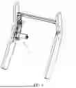
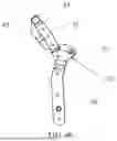
FIG. 1 schematically shows a perspective view of a headrest structure for a seat unit according to an embodiment of the present disclosure;
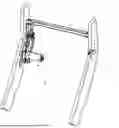
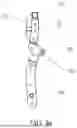
FIG. 2 schematically shows a headrest rotating mechanism according to the present disclosure;
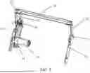
FIG. 3 schematically shows the headrest rotating device shown in FIG. 1;
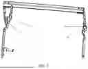
FIGS. 4a and 4b schematically show side views of the headrest rotating device, respectively;
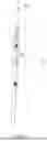
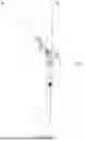
FIGS. 5a and 5b schematically show side views of the headrest rotating device shown in FIG. 1 with headrest brackets and backrest brackets, respectively;
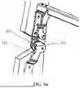
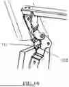
FIGS. 6a and 6b schematically show partial views of the headrest structure, respectively.
DETAILED DESCRIPTION
The technical solutions in the examples of the present disclosure are clearly and completely described and discussed below in conjunction with the attached drawings of the embodiments of the present disclosure. Obviously, the examples described herein are only some of the examples of the present disclosure but not all of them. Based on the embodiments in the present disclosure, all other embodiments obtained by those skilled in the art without creative efforts fall within the scope of protection of the present disclosure.
References herein to “an embodiment” or “embodiments” refer to particular features, structures or characteristics that may be included in at least one embodiment of the present disclosure. In the description of the present disclosure, it should be understood that the terms such as “upper”, “lower”, “left”, “right”, “top”, “bottom” indicate orientations or positional relationships based on the orientations or positional relationships shown in the drawings, and are only for facilitating the description of the present disclosure and simplifying the description, rather than indicating or implying that the referred device or element must have a specific orientation, be constructed and operated in a specific orientation, and thus should not be construed as limiting the present disclosure. Furthermore, the related terms “first”, and “second” are used for descriptive purposes only and are not to be understood as indicating or implying relative importance or implicitly specifying the number of technical features indicated. As a result, a feature defined as “first” or “second” may expressly or implicitly include one or more such features. The terms “first”, “second” and the like are used to identify different objects and are not intended to describe a particular sequence or order. It should be understood that the data herein used may be interchangeable in appropriate cases so that the it of the present disclosure described herein may be implemented in an order other than what is illustrated or described herein.
Firstly, FIG. 1 shows herein a perspective view of a headrest structure for a seat unit according to an embodiment of the present disclosure. The headrest structure includes a pair of backrest brackets 2 disposed in parallel and a pair of headrest brackets 1 extending in parallel and located above the backrest brackets. In this embodiment, the headrest brackets 1 are centrally arranged relative to the backrest brackets 2 in a view as viewed laterally from the seat unit, therefore, a longitudinal central axis A of the headrest brackets 1 coincides with a longitudinal central axis B of the backrest brackets 2. However, in a feasible embodiment not shown, the longitudinal central axis A of the headrest brackets 1 may not coincide with the longitudinal central axis B of the backrest brackets 2.
A headrest rotating device 3 is disposed between the headrest brackets and the backrest brackets, so that the headrest brackets 1 are pivotable relative to the backrest brackets 2. In the embodiments shown in FIGS. 1 to 6b, the headrest brackets 1 rotate relative to the backrest brackets 2 toward the front of the seat unit, that is, toward the direction of the leg structure, and reset, while in an embodiment not shown, the headrest brackets may also rotate relative to the backrest brackets toward the rear of the seat unit as needed and reset.
As shown in FIGS. 1 and 2, the headrest rotating device 3 includes a first side plate 31 and a second side plate 32 hinged to each other, where the first side plate 31 is attached to the headrest brackets 1, the second side plate 32 is attached to the backrest brackets 2, the first side plate 31 and the second side plate 32 are hinged via a headrest joint 33, thereby achieving pivotal connection between the headrest brackets 1 and the backrest brackets 2. A transverse member 34 is disposed between the first side plates 31. The first side plate 31 is configured as an L-shape, having a vertical section 311 and a horizontal section 312 connected to each other, where the vertical section 311 is fixedly mounted on an inner side surface of the headrest brackets via rivets, and the horizontal section 312 is fixedly connected to the transverse member 34 via screws. As shown in the figures, the first side plates 31 on both sides are configured mirror-symmetrically, and the second side plates 32 on both sides are also configured mirror-symmetrically, therefore the side plates on both sides may be manufactured by stamping using the same mold, respectively.
As shown in FIG. 3, a first lug 31a protruding toward the rear of the headrest brackets 1 is configured at a lower end of the first side plate 31, and a second lug 32a also protruding toward the rear of the headrest brackets 1 is configured at an upper end of the second side plate 32. Through holes are respectively provided in corresponding positions on the first lug 31a and the second lug 32a, and the headrest joint 33 passes through the through holes, so that the first side plate 31 and the second side plate 32 are hinged to each other. Compared to a design without lugs, due to the provision of the above first lug and second lug, the headrest joint 33, i.e., the hinge point, is moved backward. In the side views of the seat unit shown in FIGS. 5a and 5b, the headrest brackets 1 rotate forward relative to the backrest brackets 2, the position of the headrest joint 33 is not located on the imaginary longitudinal central axis A/B of the headrest brackets and the backrest brackets to which the first side plate 31 and the second side plate 32 are attached, but is moved backward relative to the imaginary longitudinal central axis, this enables the position of the hinge point to be moved further toward the rear edges of the headrest brackets 1 and the backrest brackets 2 when the first side plate 31 and the second side plate 32 are mounted on the headrest brackets 1 and the backrest brackets 2, as close as possible to the back side of the backrest covering material, thereby causing that part to be stretched only slightly when the headrest pivots, thus reducing the generation of creases.
A limiting member 313 protruding inward is configured at a lower end portion of the first side plate 31, and a first limiting portion 321 and a second limiting portion 322 in the form of dimples are configured at an edge region of an upper end of the second side plate 32, the limiting member 313 is configured to abut against the first limiting portion 321 and the second limiting portion 322. FIG. 5a shows an initial position where the headrest brackets are not pivoted relative to the backrest brackets, and FIG. 5b shows a limit position where the headrest brackets are pivoted relative to the backrest brackets to a maximum extent. In the initial position shown in FIG. 6a, the limiting member 313 of the first side plate 31 abuts against the first limiting portion 321 of the second side plate 32, thereby preventing the headrest brackets 1 from tilting backward; in the limit position shown in FIG. 6b, the limiting member 313 of the first side plate 31 abuts against the second limiting portion 322 of the second side plate 32, thereby preventing further forward pivoting of the headrest brackets. According to the present disclosure, during the movement from the initial position to the limit position, the angular change between the headrest brackets and the backrest brackets is at most 50 degrees.
The headrest structure further includes an actuating motor 4 configured to drive the headrest rotating device 3 to move. In the embodiment shown in FIG. 1, the actuating motor 4 is configured as a linear actuating motor; in an embodiment not shown, any other suitable electric motor may also be used as the actuating motor. The actuating motor 4 includes a motor head 41 and an actuating rod 42 configured to extend and retract relative to the motor head 41. The motor head 41 is mounted on one of the second side plates 32 via a fixing pin 44, and the actuating rod 42 acts on the first side plate 31 via a driving link 43, where a lower end of the driving link 43 is pivotally connected in a through hole at a free end of the driving link 43 via a pin and is fixed against loss via a retaining pin, an upper end of the driving link 43 is welded to the transverse member 34, thereby causing the driving force provided by the actuating motor to be applied to the transverse member 34 of the first side plate 31 via the driving link 43. In this case, in the side views shown in FIGS. 5a and 5b, the imaginary longitudinal central axis A of the headrest brackets 1 coincides with the imaginary longitudinal central axis B of the backrest brackets 2, and the headrest joint 33 is designed close to the rear edges of the headrest brackets 1 and the backrest brackets 2 relative to the aforementioned longitudinal central axes A and B. Therefore, even if the driving motor 4 is arranged centrally relative to the front-rear direction of the backrest portion or even slightly rearward, the action point of the actuating rod 42 on the transverse member 34 via the driving link 43 is still located forward of the headrest joint 33, thereby advantageously enabling the transverse member 34 to flip forward.
When it is required to transition the headrest brackets from the initial position to the limit position, the actuating rod 42 of the actuating motor 4 retracts to pull the driving link 43, thereby causing the transverse member 34 to flip forward, and further causing the first side plate 31 to pivot forward relative to the second side plate 32, until the limiting member 313 of the first side plate 31 abuts against the second limiting portion of the second side plate 32, thereby achieving the transition of the headrest brackets 1 from the initial position shown in FIG. 4a to the limit position shown in FIG. 4b. When it is required to reset the headrest brackets from the limit position to the initial position, the actuating rod 42 of the actuating motor 4 extends to push the driving link, thereby causing the transverse member 34 to flip reversely, and causing the first side plate 31 to pivot backward relative to the second side plate 32, until the limiting member 313 of the first side plate 31 abuts against the first limiting portion of the second side plate 32, thereby achieving the reset of the headrest brackets 1 from the limit position to the initial position.
REFERENCE NUMERALS LIST
-
- 1 headrest bracket
- 2 backrest bracket
- 3 headrest rotating device
- 31 first side plate
- 31a first lug
- 311 vertical section
- 312 horizontal section
- 313 limiting member
- 32 second side plate
- 32a second lug
- 321 first limiting portion
- 322 second limiting portion
- 33 headrest joint
- 34 transverse member
- 4 actuating motor
- 41 motor head
- 42 actuating rod
- 43 driving link
- 44 fixing pin
Claims
What is claimed is:1. A headrest rotating mechanism, configured to rotate a headrest disposed above a backrest of a seat unit relative to the backrest forward or backward, the headrest rotating mechanism comprising a headrest rotating device and an actuating motor configured to drive the headrest rotating device to move,
wherein the headrest rotating device comprises a pair of first side plates configured to attach the headrest and a pair of second side plates configured to attach the backrest, the first side plates and the second side plates are movably connected via a headrest joint, the headrest joint is disposed offset backward relative to a longitudinal central axis of the headrest and/or the backrest as viewed laterally from the seat unit when the headrest is configured to pivot forward relative to the backrest; the headrest joint is disposed offset forward relative to the longitudinal central axis of the headrest and/or the backrest as viewed laterally from the seat unit when the headrest is configured to pivot backward relative to the backrest.
2. The headrest rotating mechanism according to claim 1, wherein a motor head of the actuating motor is connected to the second side plate, and an actuating rod of the actuating motor acts on the first side plate via a driving link.
3. The headrest rotating mechanism according to claim 2, wherein the first side plate comprises a transverse member extending transversely, wherein the motor head is mounted on the second side plate via a fixing pin, and the actuating rod is connected to the transverse member.
4. The headrest rotating mechanism according to claim 2, wherein a connection point between the motor head and the second side plate and a connection point between the driving link and the first side plate are located on two sides of the headrest joint.
5. The headrest rotating mechanism according to claim 1, wherein, when the headrest is configured to pivot forward relative to the backrest, a lower end of the first side plate is configured with a first lug protruding toward a rear of the headrest laterally, and an upper end of the second side plate is configured with a second lug protruding toward the rear of the headrest; when the headrest is configured to pivot backward relative to the backrest, the lower end of the first side plate is configured with the first lug protruding toward a front of the headrest, and the upper end of the second side plate is configured with the second lug protruding toward the front of the headrest;
wherein the first lug and the second lug are pivotally connected via the headrest joint.
6. The headrest rotating mechanism according to claim 1, wherein the first side plate is configured to pivot relative to the second side plate at an angle of up to 50°.
7. The headrest rotating mechanism according to claim 6, wherein an upper end of the second side plate is configured with a first limiting portion and a second limiting portion, a lower end of the first side plate is configured with a limiting member, wherein the limiting member abuts against the first limiting portion when the first side plate is not pivoted relative to the second side plate, and the limiting member abuts against the second limiting portion when the first side plate is pivoted relative to the second side plate at a maximum angle.
8. The headrest rotating mechanism according to claim 3, wherein the transverse member is connected between the pair of first side plates.
9. The headrest rotating mechanism according to claim 1, wherein the pair of first side plates and the pair of second side plates are respectively configured mirror-symmetrically.
10. A headrest structure for a seat unit, comprising a pair of headrest brackets disposed in parallel, a pair of backrest brackets extending in parallel, a headrest rotating device configured to pivotally connect the headrest brackets relative to the backrest brackets, and an actuating motor configured to drive the headrest rotating device to move, wherein the headrest rotating device comprises a pair of first side plates attached to the headrest brackets and a pair of second side plates attached to the backrest brackets, the first side plates and the second side plates are movably connected via a headrest joint, wherein the headrest joint is disposed offset backward relative to a longitudinal central axis of the headrest brackets and/or the backrest brackets as viewed laterally from the seat unit when the headrest brackets are configured to pivot forward relative to the backrest brackets; the headrest joint is disposed offset forward relative to the longitudinal central axis of the headrest brackets and/or the backrest brackets as viewed laterally from the seat unit when the headrest brackets are configured to pivot backward relative to the backrest brackets.
11. The headrest structure according to claim 10, wherein a motor head of the actuating motor is connected to the second side plate, and an actuating rod of the actuating motor is connected to the first side plate via a driving link.
12. The headrest structure according to claim 11, wherein the first side plate comprises a transverse member extending transversely, wherein the motor head is mounted on the second side plate via a fixing pin, and the actuating rod is connected to the transverse member.
13. The headrest structure according to claim 11, wherein a connection point between the motor head and the second side plate and a connection point between the driving link and the first side plate are located on two sides of the headrest joint.
14. The headrest structure according to claim 10, wherein, when the headrest bracket is configured to pivot forward relative to the backrest bracket, a lower end of the first side plate is configured with a first lug protruding toward a rear of the headrest bracket, and an upper end of the second side plate is configured with a second lug protruding toward the rear of the headrest bracket; when the headrest bracket is configured to pivot backward relative to the backrest bracket, the lower end of the first side plate is configured with the first lug protruding toward a front of the headrest bracket, and the upper end of the second side plate is configured with the second lug protruding toward the front of the headrest bracket;
wherein the first lug and the second lug are pivotally connected via the headrest joint.
15. The headrest structure according to claim 10, wherein the headrest bracket is configured to pivot relative to the backrest bracket between an initial position and a limit position, the headrest bracket is not pivoted relative to the backrest bracket in the initial position, the headrest bracket is pivoted relative to the backrest bracket to a maximum extent in the limit position, so that an included angle between the headrest bracket and the backrest bracket changes, wherein the included angle changes by at most 50°.
16. The headrest structure according to claim 13, wherein an upper end of the second side plate is configured with a first limiting portion and a second limiting portion, a lower end of the first side plate is configured with a limiting member, wherein the limiting member abuts against the first limiting portion in an initial position, and the limiting member abuts against the second limiting portion in a limit position.
17. The headrest structure according to claim 12, wherein the transverse member is configured to be connected between the pair of headrest brackets disposed in parallel.
18. The headrest structure according to claim 10, wherein the pair of first side plates and the pair of second side plates are respectively configured mirror-symmetrically.
19. A seat unit, comprising a backrest portion and the headrest rotating mechanism according to claim 1.
20. A seat unit, comprising a backrest portion and the headrest structure according to claim 10 disposed above the backrest portion.
Images & Drawings included:
Sources:
- United States Patent and Trademark Office - verify current appl. status at the USPTO↗
Recent applications in this class:
- » 20250268381 2025-08-28
POWERED MOUNTING BRACKET ASSEMBLY FOR FURNITURE HEADREST - » 20250261760 2025-08-21
ANGLE ADJUSTMENT SYSTEM - » 20250143468 2025-05-08
HEIGHT CONTROL APPARATUS FOR HEADREST AND CHAIR COMPRISING SAME - » 20250024950 2025-01-23
HEIGHT ADJUSTMENT MECHANISM FOR A MOVABLE SUPPORT PART OF SEATING FURNITURE AND SEATING FURNITURE - » 20240374036 2024-11-14
TRAVEL SUPPORT STRUCTURE - » 20230301436 2023-09-28
HEADREST - » 20230232989 2023-07-27
Adjustable chair headrest - » 20230137499 2023-05-04
Quickly installed headrest adjustment device - » 20220369814 2022-11-24
Adjustable headrest mechanism and chair having same - » 20220312976 2022-10-06
Electromotor adjusting unit for adjusting the inclination of a support part of an item of seating furniture