PORTABLE PRAYER KNEELER
US20260013640A1
2026-01-15
18/770,365
2024-07-11
Smart Summary: A portable prayer kneeler is designed to make praying more comfortable. It has a knee rest and an arm rest for support. The knee rest has adjustable legs that can change length, with a padded area for the knees. The arm rest also has adjustable legs and a padded area for the elbows. Both parts are connected, allowing users to find a comfortable position while praying. 🚀 TL;DR
Abstract:
A portable prayer kneeler includes a knee rest portion and an arm rest portion. The knee rest portion includes a pair of base leg structures, each being adjustable in length and having a first end and a second end, and a knee pad panel attached to the second ends of the base leg structures. The arm rest portion includes a pair of support leg structures, each being adjustable in length and having a first end and a second end, and an elbow pad panel attached to the second ends of the support leg structures. The first ends of the support leg structures are attached one each to the first ends of the base leg structures.
Applicant:
Interested in similar patents?
Get notified when new applications in this technology area are published.
Classification:
A47C16/04 » CPC main
rests or supports for feet, legs, arms, back or head Stand-alone Prayer-stools; Kneeling stools; Kneeling supports
Description
CROSS-REFERENCE TO RELATED APPLICATIONS
Not Applicable
STATEMENT REGARDING FEDERALLY SPONSORED RESEARCH OR DEVELOPMENT
Not Applicable
THE NAMES OF THE PARTIES TO A JOINT RESEARCH AGREEMENT
Not Applicable
INCORPORATION-BY-REFERENCE OF MATERIAL SUBMITTED ON A COMPACT DISC OR AS A TEXT FILE VIA THE OFFICE ELECTRONIC FILING SYSTEM
Not Applicable
STATEMENT REGARDING PRIOR DISCLOSURES BY THE INVENTOR OR JOINT INVENTOR
Not Applicable
BACKGROUND OF THE INVENTION
(1) Field of the Invention
The disclosure relates to religious devices and accessories and more particularly pertains to a new portable prayer kneeler that is collapsible and expandable to permit a user to easily transport the prayer kneeler from one location to another and store the prayer kneeler when not in use.
(2) Description of Related Art Including Information Disclosed Under 37 CFR 1.97 and 1.98
The prior art relates to religious devices and accessories. The prior art, as best understood, does not disclose portable prayer kneeler that is collapsible and expandable via telescoping leg and base portions.
BRIEF SUMMARY OF THE INVENTION
An embodiment of the disclosure meets the needs presented above in a portable prayer kneeler generally comprising a knee rest portion and an arm rest portion. The knee rest portion includes a pair of base leg structures, each being adjustable in length and having a first end and a second end, and a knee pad panel attached to the second ends of the base leg structures. The arm rest portion includes a pair of support leg structures, each being adjustable in length and having a first end and a second end, and an elbow pad panel attached to the second ends of the support leg structures. The first ends of the support leg structures are attached one each to the first ends of the base leg structures.
There has thus been outlined, rather broadly, the more important features of the disclosure in order that the detailed description thereof that follows may be better understood, and in order that the present contribution to the art may be better appreciated. There are additional features of the disclosure that will be described hereinafter and which will form the subject matter of the claims appended hereto.
The objects of the disclosure, along with the various features of novelty which characterize the disclosure, are pointed out with particularity in the claims annexed to and forming a part of this disclosure.
BRIEF DESCRIPTION OF SEVERAL VIEWS OF THE DRAWING(S)
The disclosure will be better understood and objects other than those set forth above will become apparent when consideration is given to the following detailed description thereof. Such description makes reference to the annexed drawings wherein:
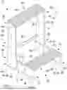
FIG. 1 is a perspective view of a portable prayer kneeler according to an embodiment of the disclosure.
FIG. 2 is a side view of an embodiment of the disclosure.
FIG. 3 is a rear view of an embodiment of the disclosure.
FIG. 4 is a bottom view of an embodiment of the disclosure.
FIG. 5 is a close-up view of a portion of an embodiment of the disclosure.
FIG. 6 is a perspective view of an embodiment of the disclosure in use.
FIG. 7 is a perspective view of an embodiment of the disclosure in use.
DETAILED DESCRIPTION OF THE INVENTION
With reference now to the drawings, and in particular to FIGS. 1 through 7 thereof, a new portable prayer kneeler embodying the principles and concepts of an embodiment of the disclosure and generally designated by the reference numeral 10 will be described.
As best illustrated in FIGS. 1 through 7, the portable prayer kneeler 10 generally comprises a knee rest portion 12 and an arm rest portion 14. The knee rest portion 12 includes a pair of base leg structures 16, each being adjustable in length and having a first end 18 and a second end 20, and a knee pad panel 22 attached to the second ends 20 of the base leg structures 16. The arm rest portion 14 includes a pair of support leg structures 24, each being adjustable in length and having a first end 26 and a second end 28, and an elbow pad panel 30 attached to the second ends 20 of the support leg structures 24. The first ends 26 of the support leg structures 24 are attached one each to the first ends 18 of the base leg structures 16.
The knee pad panel 22 includes a knee cushion 32 and a crosspiece 34. The knee cushion 32 is attached to one side of the crosspiece 34 and the second ends 20 of the base leg structures 16 are attached to an opposite side. The elbow pad panel 30 includes an elbow cushion 36 and a crosspiece 38. The elbow cushion 36 is attached to one side of the crosspiece 38 and the second ends 28 of the support leg structures 24 are attached to an opposite side.
In the exemplary embodiment, each of the base leg structures 16 includes base leg telescoping sections 40. Similarly, each of the support leg structures 24 includes support leg telescoping sections 42. The telescoping design allows a user to selectively increase and decrease the length of the base leg structures 16 and the support leg structures 24. Each of the base leg structures 16 includes base leg locking arrangements 44 designed to releasably lock the base leg telescoping sections 40 in an extended position. Similarly, each of the support leg structures 24 includes support leg locking arrangements 46 designed to releasably lock the support leg telescoping sections 42 in an extended position. The locking arrangements 44, 46 could be spring-loaded buttons 48 that interact with openings 50, though other locking arrangements, such as tabs or snap fit connections could be used. FIG. 1 shows the base leg structures 16 and the support leg structures 24 fully extended, FIG. 6 shows them partially extended or partially collapsed, and FIG. 7 shows them fully collapsed.
The base leg telescoping sections 40 of each of the base leg structures 16 include a first storage section 52 positioned at the second end 20. The first storage section 52 is designed to temporarily contain all other of the base leg telescoping sections 40 when the base leg structures 16 are in the fully collapsed position, such as shown in FIG. 7. Similarly, the support leg telescoping sections 42 of each of the support leg structures 24 comprise a second storage section 54 positioned at the first end 26. The second storage section 54 is designed to temporarily contain all other of the support leg telescoping sections 42 when the support leg structures 24 are in the fully collapsed position.
As best seen in FIG. 2, the second storage section 54 has a height greater than a height of the first storage section 52. As a result, as shown in FIG. 7, when both the support leg structures 24 and the base leg structures 16 are in the fully collapsed position, the knee pad panel 22 is positioned between the support leg structures 24 and adjacent the knee pad panel 22.
Each of the first storage section 52 and the second storage section 54 includes rubber feet 56. To provide additional strength, the arm rest portion 14 further includes a reinforcement piece 58 positioned transversely and attached to the second storage sections 54.
In use, a user can place the both the support leg structures 24 and the base leg structures 16 in the fully collapsed position so that the portable prayer kneeler 10 is very compact and easily transported from one location to another. When the user wishes to use the portable prayer kneeler 10, the user extends both the support leg structures 24 and the base leg structures 16 to a partially or fully extended position as desired, such as shown in FIG. 1.
With respect to the above description then, it is to be realized that the optimum dimensional relationships for the parts of an embodiment enabled by the disclosure, to include variations in size, materials, shape, form, function and manner of operation, assembly and use, are deemed readily apparent and obvious to one skilled in the art, and all equivalent relationships to those illustrated in the drawings and described in the specification are intended to be encompassed by an embodiment of the disclosure.
Therefore, the foregoing is considered as illustrative only of the principles of the disclosure. Further, since numerous modifications and changes will readily occur to those skilled in the art, it is not desired to limit the disclosure to the exact construction and operation shown and described, and accordingly, all suitable modifications and equivalents may be resorted to, falling within the scope of the disclosure. In this patent document, the word “comprising” is used in its non-limiting sense to mean that items following the word are included, but items not specifically mentioned are not excluded. A reference to an element by the indefinite article “a” does not exclude the possibility that more than one of the element is present, unless the context clearly requires that there be only one of the elements.
Claims
I claim:1. A portable prayer kneeler comprising:
a knee rest portion comprising a pair of base leg structures, each being adjustable in length and having a first end and a second end, and a knee pad panel attached to said second ends of said base leg structures; and
an arm rest portion comprising a pair of support leg structures, each being adjustable in length and having a first end and a second end, and an elbow pad panel attached to said second ends of said support leg structures, wherein said first ends of said support leg structures are attached one each to said first ends of said base leg structures.
2. The portable prayer kneeler of claim 1, wherein each of said base leg structures comprises base leg telescoping sections.
3. The portable prayer kneeler of claim 2, wherein each of said base leg structures comprises base leg locking arrangements configured to releasably lock said base leg telescoping sections in an extended position.
4. The portable prayer kneeler of claim 1, wherein said knee pad panel comprises a knee cushion and a crosspiece, wherein said knee cushion is attached to one side of said crosspiece and said second ends of said base leg structures are attached to an opposite side.
5. The portable prayer kneeler of claim 1, wherein each of said support leg structures comprises support leg telescoping sections.
6. The portable prayer kneeler of claim 5, wherein each of said support leg structures comprises support leg locking arrangements configured to releasably lock said support leg telescoping sections in an extended position.
7. The portable prayer kneeler of claim 1, wherein said elbow pad panel comprises an elbow cushion and a crosspiece, wherein said elbow cushion is attached to one side of said crosspiece and said second ends of said support leg structures are attached to an opposite side.
8. The portable prayer kneeler of claim 2, wherein each of said support leg structures comprises support leg telescoping sections.
9. The portable prayer kneeler of claim 8, wherein:
said base leg telescoping sections of each of said base leg structures comprise a first storage section disposed at said second end and configured to temporarily contain all other of said base leg telescoping sections when said base leg structures are in a fully collapsed position; and
said support leg telescoping sections of each of said support leg structures comprise a second storage section disposed at first second end and configured to temporarily contain all other of said support leg telescoping sections when said support leg structures are in a fully collapsed position.
10. The portable prayer kneeler of claim 9, wherein said second storage section has a height greater than a height of said first storage section such that, when both said support leg structures and said base leg structures are in a fully collapsed position, said knee pad panel is positioned between said support leg structures and adjacent said knee pad panel.
11. The portable prayer kneeler of claim 9, wherein each of said first storage section and said second storage section comprises rubber feet.
12. The portable prayer kneeler of claim 1, wherein said arm rest portion further comprises a reinforcement piece disposed transversely and attached to said second storage sections.
13. A portable prayer kneeler comprising:
a knee rest portion comprising a pair of base leg structures, each being adjustable in length and having a first end and a second end, and a knee pad panel attached to said second ends of said base leg structures, wherein:
each of said base leg structures comprises base leg telescoping sections,
each of said base leg structures comprises base leg locking arrangements configured to releasably lock said base leg telescoping sections in an extended position,
said knee pad panel comprises a knee cushion and a crosspiece, wherein said knee cushion is attached to one side of said crosspiece and said second ends of said base leg structures are attached to an opposite side,
said base leg telescoping sections of each of said base leg structures comprise a first storage section disposed at said second end and configured to temporarily contain all other of said base leg telescoping sections when said base leg structures are in a fully collapsed position; and
an arm rest portion comprising a pair of support leg structures, each being adjustable in length and having a first end and a second end, and an elbow pad panel attached to said second ends of said support leg structures, wherein said first ends of said support leg structures are attached one each to said first ends of said base leg structures, wherein:
each of said support leg structures comprises support leg telescoping sections;
each of said support leg structures comprises support leg locking arrangements configured to releasably lock said support leg telescoping sections in an extended position,
said elbow pad panel comprises an elbow cushion and a crosspiece, wherein said elbow cushion is attached to one side of said crosspiece and said second ends of said support leg structures are attached to an opposite side,
said support leg telescoping sections of each of said support leg structures comprise a second storage section disposed at said second end and configured to temporarily contain all other of said support leg telescoping sections when said support leg structures are in a fully collapsed position,
said second storage section has a height greater than a height of said first storage section such that, when both said support leg structures and said base leg structures are in a fully collapsed position, said knee pad panel is positioned between said support leg structures and adjacent said knee pad panel,
each of said first storage section and said second storage section comprises rubber feet, and
said arm rest portion further comprises a reinforcement piece disposed transversely and attached to said second storage sections.
Images & Drawings included:


Sources:
- United States Patent and Trademark Office - verify current appl. status at the USPTO↗
Recent applications in this class:
- » 20250359682 2025-11-27
Portable Prayer Stool Assembly - » 20240407556 2024-12-12
PRAYER AND MEDITATION STAND - » 20230397736 2023-12-14
Prayer and meditation stand - » 20230117693 2023-04-20
Prayer Station Device - » 20220095800 2022-03-31
Method and apparatus for creating a kneeler pad using a thermoforming process - » 20210227984 2021-07-29
Knee Pad With Rollers - » 20190320802 2019-10-24
APPARATUS FOR PROVIDING BALANCE AND STABILITY WHILE STANDING - » 20180153308 2018-06-07
Ergonomic puncture-resistant pads - » 20170280879 2017-10-05
Ergonomic Support Device for Weight of a User - » 20170143128 2017-05-25
Apparatus for providing balance and stability while standing