GOLF CLUB GRIP WITH GRIP CONTROL PORTION
US20260014432A1
2026-01-15
19/261,055
2025-07-07
Smart Summary: A golf club grip is designed to be held comfortably by a user. It has an outer surface for gripping and an inner surface that fits onto the golf club shaft. The grip has a main part that connects to the top of the shaft and a control portion that extends down to the bottom. This control portion is angled differently than the main part, allowing for better thumb and forefinger contact. This design helps golfers have better control over their swings. 🚀 TL;DR
Abstract:
A grip for a golf club includes an outer surface adapted to be grasped by a user, an inner surface the defines a cavity adapted to receive part of a shaft of a golf club, a main portion having a first end adapted to be received adjacent to a top end of the shaft and a second end spaced from the first end, the main portion defines part of the outer surface, the inner surface, and a control portion. The control portion extends from the main portion to a bottom end of the grip, and defines part of the inner and outer surfaces. At the outer surface, the control portion is arranged at a greater angle relative to a central axis of the cavity than the main portion, and the control portion is arranged to be contacted by a thumb and forefinger of a hand holding the grip.
Applicant:
Interested in similar patents?
Get notified when new applications in this technology area are published.
Classification:
A63B53/14 » CPC main
Golf clubs Handles
A63B53/007 » CPC further
Golf clubs Putters
A63B53/00 IPC
Golf clubs
Description
REFERENCE TO RELATED APPLICATIONS
This application claims the benefit of U.S. Provisional Application Ser. No. 63/669,618 filed on Jul. 10, 2024 the content of which is incorporated herein by reference in its entirety.
TECHNICAL FIELD
The present disclosure relates generally to a grip for a golf club.
BACKGROUND
Golf clubs include a grip at an end of the club opposite to a club head and adapted to be engaged by one or both hands of a user or player. It is difficult to control a golf club and maintain a desired orientation and swing path for the head of the club. An improved grip is needed that provides better control of the golf club throughout a swing
SUMMARY
In at least some implementations, a grip for a golf club includes an outer surface adapted to be grasped by a user, an inner surface the defines a cavity adapted to receive part of a shaft of a golf club, a main portion having a first end adapted to be received adjacent to a top end of the shaft and a second end spaced from the first end, the main portion defines part of the outer surface and part of the inner surface, and a control portion. The control portion extends from the main portion to a bottom end of the grip, and the control portion defines part of the outer surface and part of the inner surface. The portion of the outer surface that is defined by the control portion is arranged at a greater angle relative to a central axis of the cavity than is the portion of the outer surface defined by the main portion, and the control portion is arranged to be contacted by a thumb and forefinger of a hand holding the grip.
In at least some implementations, the angle of the portion of the outer surface defined by the control portion to the central axis is between or equal to eight degrees and twenty-five degrees.
In at least some implementations, the angle of the portion of the outer surface defined by the main portion to the central axis is between or equal to zero degrees and four degrees.
In at least some implementations, the control portion has an axial length of between or equal to 0.625 in and 1.5 in. In at least some implementations, a combined axial length of the main portion and the control portion is between or equal to 7 in and 9 in.
In at least some implementations, the control portion has a thickness between the inner surface and the outer surface at an upper end of between 0.33 in and 0.25 in, inclusive, and a thickness at the lower end 38 of between 0.2 in and 0.1 in, inclusive, and the upper end is adjacent to the main portion and the lower end is at the bottom end of the grip.
In at least some implementations, an included angle of between 174 degrees and 165 degrees, inclusive, is defined between the portion of the outer surface defined by the main portion and the portion of the outer surface defined by the control portion.
In at least some implementations, the control portion includes multiple discontinuities such that the portion of the outer surface defined by the control portion is not a smooth frustum-shaped or frustoconical portion of the grip. In at least some implementations, the discontinuities are defined by a wavy outer surface having differing outer diameter along the axial length of at least part of the control portion. In at least some implementations, the discontinuities include one or more of grooves or other inwardly extending voids, and outwardly extending nubs or ribs. In at least some implementations, the discontinuities include multiple angled and intersecting ribs or grooves.
In at least some implementations, the main portion is configured to receive all of a top hand of a user and most of a second hand of the user with the control portion configured to be contacted by an index finger and thumb of the second hand.
In at least some implementations, the grip is adapted for use on a putter.
In at least some implementations, a grip for a golf club includes a main portion and a control portion. The main portion has a first end adapted to be received adjacent to a top end of the shaft and a second end spaced from the first end, the main portion has an inner surface that defines part of a cavity adapted to receive part of a shaft of a golf club, and the main portion has an outer surface that is at a first angle relative to a central axis of the cavity. The control portion extends from the main portion to a bottom end of the grip, has an inner surface that defines part of the cavity, and an outer surface arranged at a second angle relative to the central axis that is greater than the first angle. The control portion has an axial length of between 0.625 in and 1.5 in and the main portion has an axial length of between 6 in and 8 in, and an included angle is defined between the outer surface of the main portion and the outer surface of the control portion that is between 174 degrees and 165 degrees, inclusive.
In at least some implementations, the outer surface of the control portion is frustoconical and the second angle is defined by the outer surface of the control portion.
In at least some implementations, the outer surface of the control portion is defined in part by discontinuities and the outer surface of the control portion is not frustoconical in shape, and the second angle is defined by a center line through a center of mass between the inner surface in the control portion and the outer surface in the control portion. In at least some implementations, the discontinuities are defined by one or more of a wavy outer surface having differing outer diameter along the axial length of at least part of the control portion, one or more of grooves or other inwardly extending voids, and/or outwardly extending nubs or ribs.
In at least some implementations, the main portion is configured to receive all of a top hand of a user and most of a second hand of the user with the control portion configured to be contacted by an index finger and thumb of the second hand.
BRIEF DESCRIPTION OF THE DRAWINGS
The following detailed description of preferred implementations and best mode will be set forth with regard to the accompanying drawings, in which:
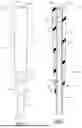
FIG. 1 is a front view of a golf grip with a grip control portion;
FIG. 2 is a cross-sectional view taken generally along line 2-2 of FIG. 1;
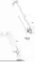
FIG. 3 is a partial perspective view showing a golf club being held by a user or
player;
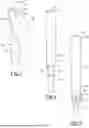
FIG. 4 is a front view of a golf grip;
FIG. 5 is a front view of a golf grip;
FIG. 6 is a front view of a golf grip;
FIG. 7 is a front view of a golf grip;
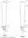
FIG. 8 is a front view of a golf grip for a putter; and
FIG. 9 is a front view of a golf grip for a putter.
DETAILED DESCRIPTION
Referring in more detail to the drawings, FIGS. 1 and 2 shows part of a golf club 10 including a golf grip 12 and a shaft 14. As shown in FIG. 2. the grip 12 includes a cavity 16 that is defined by an inner surface 18 of the grip 12 and the cavity 16 extends partly or entirely through the length of the grip 12 from or near a top end 20 and to a distal, bottom end 22 of the grip 12. Part of the shaft 14 including a first end 24 of the shaft 14 is received in the cavity 16, and is covered by the grip 12. The portion of the shaft 14 received in the cavity 16 may have a constant or tapered outer diameter, and may be received with a friction fit within the cavity 16 and/or tape or other adhesive may be used to fix the grip 12 to the shaft 14, in known manner. In this way, the grip 12 is secured to the shaft 14 and does not rotate or slide relative to the shaft 14. The shaft 14 may be formed of any suitable material, including by way of non-limiting examples, metal, graphite or other composite and wood. At an opposite, second end of the club, not shown, a club head is secured to the shaft 14 in known manner.
As shown in FIGS. 1-3, the grip 12 includes an outer surface 26 arranged to be grasped by a user's or player's hands, and the outer surface 26 is defined by a main portion 28 and a control portion 30. The main portion 28 extends from a first end 32 near or at the top end 20 of the grip 12 to a second end 34 that transitions to the control portion 30. The main portion 28 may be cylindrical generally cylindrical, or have any suitable shape and size (e.g. outer diameter), including but not limited to shapes and sizes permitted by the rules of golf promulgated by the United States Golf Association (USGA) and/or the Royal and Ancient Golf Club (the “R&A”). A thickness of the grip 12 may be defined between the inner surface 18 and the outer surface 26, and the grip 12 may have a constant outer diameter or a varying outer diameter, as desired. In at least some implementations, the shaft 14 has a circular outer surface, in cross-section, and is tapered so that the shaft 14 has a larger diameter at the first end 24 than at the second end near the club head. The grip cavity 16 may be shaped similarly as the portion of the outer surface of the shaft 14 that is received in the cavity 16, and the outer surface 26 of the grip 12 may follow the same angle as the inner surface 18, or the outer surface 26 may be oriented at a different angle than the inner surface 18 (such that the grip thickness would change along the axial length of the grip 12), as desired.
The control portion 30 extends from an upper end 36 at the second end 34 of the main portion 28 to a lower end 38 at the bottom end 22 of the grip 12. A transition 40 at which the angle or orientation of the outer surface 26 changes, is defined between the second end 34 of the main portion 28 and the upper end 36 of the control portion 30. That is, the outer surface 26 may follow a first angle 42 along the main portion 28 of the grip 12, shown by line 44 and a central axis 46 of the grip cavity 16, and the outer surface 26 may follow a second angle 48 along the control portion 30 of the grip 12, as shown by line 50 relative to axis 46. The second angle 48 is different from and greater than the first angle 42 so that the control portion 30 is tapered at a desired angle. In at least some implementations, the angles 42, 48 are defined by the outer surface 26 in the main portion 28 and control portion 30 of the grip 12 (i.e. the lines 44 and 50 follow the outer surface 26 of the grip 12 in the main and control portions 28, 30 of the grip 12), or along a center line 51 through a center of mass between the inner and outer surfaces of the grip 12′, for grips in which the outer surface (e.g. in the control portion 30) is not flat or linear (e.g. is wavy or ribbed or other shape, as shown in FIG. 4).
In at least some implementations, the main portion 28 has a length of between 8.0 inches to 6.0 inches, and the first angle 42 is between zero degrees and four degrees, inclusive. The diameter of the main portion 28, at the top end 20 of the grip 12, may be selected as desired, and different diameters may be provided as is known. Further, the control portion 30 may have an axial length of between 0.625 in and 1.5 in. The overall grip length may be selected as desired, such as to conform with the USGA's and R&A's Rules of Golf. In at least some implementations, the overall grip length is between 7 in and 9 in.
In the example of FIGS. 1-3, the control portion 30 is relatively smooth and the outer surface 26 is linear, may be frustoconical, and defines the second angle 48 which may be between eight (8) degrees and twenty-five (25) degrees, inclusive. Further, the control portion 30 has an axial length of between the upper end 36 and lower end 38 of between 0.625 in and 1.5 in, inclusive, and may have a thickness at the upper end 36 of between 0.33 in and 0.25 in, inclusive, and a thickness at the lower end 38 of between 0.2 in and 0.1 in, inclusive. Further, an obtuse included angle 54 (FIG. 1) is defined between the line defining the first angle 42 and the line defining the second angle 48, as shown in FIG. 2, and this included angle may be between 174 degrees and 165 degrees, inclusive.
In FIGS. 4-7 reference numerals for certain parts of the grips shown are the same as those used for the grip 12, for ease of description and understanding. FIG. 5 shows a grip 60 with a control portion 30 that includes discontinuities in the form of angled, and intersecting ribs 62 extending outwardly from the outer surface 26 and designed to provide a different or improved feel to the control portion 30 when gripped by a player. Similarly, FIG. 6 shows a grip 64 with a control portion 30 that includes partially-spherical nubs 66 as discontinuities that are spaced apart and extend outwardly from the outer surface 26 of the control portion 30, and FIG. 7 shows a grip 68 with a control portion 30 having inwardly extending voids, such as arcuate grooves 70, as discontinuities that extend inwardly into the outer surface 26 control portion 30. The size, shape and arrangement of the discontinuities can vary, as desired, to provide a desired feel when gripped by a player. The forms of discontinuities shown in FIGS. 4-7 are representative and not intended to limit the shapes, sizes or quantities of discontinuities that may be provided. The discontinuities make the outer surface of the control portion not a smooth, frustum or frustoconical shape, although the overall shape may remain generally frustum shaped or frustoconical, with surface deviations from a smooth frustum or frustoconical shaped.
FIGS. 8 and 9 show grip 72, 74 designed for use on a putter, and it is noted that current golf rules permit a wider range of shapes and sizes for putter grips than for other golf clubs. The grip 72 in FIG. 8 is generally cylindrical and has a constant diameter outer surface 26 in the main portion 28, and is thicker than the grip 74 shown in FIG. 9 which has a tapered outer surface 26 in the main portion 28 thereof. The putter grips are shown with discontinuities 76 in the control portions 30, such as described above with reference to FIGS. 4-7. In at least some implementations, the putter grips 72, 74 may have a main portion 28 and a control portion 30 with lengths and an overall grip length as noted above for the other grips shown.
In normal use of the golf club 10, a player holds the club with both hands on the outer surface 26 of the grip, and swings the club to hit a golf ball. Typically, the player's hands are arranged with a top hand nearer the top end 20 of the grip and a bottom hand 80, shown in FIG. 3, below the top hand and nearer to the bottom end 22 of the grip 12. In at least some implementations, the main portion 28 has a length designed to fit most of both hands of a player on the main portion 28. In more detail, the grip may be designed so that the top hand of a player and the bottom hand 80, except for all or part of a thumb 82 and index or forefinger 84 of the bottom hand 80, are entirely received on the main portion 28 of the grip. All of part of the area of the thumb 82 and forefinger 84 that engage the golf grip may be received on the control portion 30, with the thumb 82 generally opposite to the area of the forefinger 84 that is engaged with the grip 12. In this way, a user may trap the control portion 30 between the thumb 82 and forefinger 84 of their bottom hand 80.
The thumb and forefinger of a hand are used in gripping and picking up many things in daily life, and people develop great control and touch, sometimes called fine motor skills, in utilizing the thumb and forefinger in everyday applications. For example, when utilizing a computer mouse or writing with a pen, the majority of the work is done with the thumb and index or forefinger. In golf, most players mark their golf ball position on the green with a coin, utilizing their dominant hand's thumb and forefinger to do so. When returning the ball to the green to putt, golfers use the same thumb and finger to line up the ball's alignment aid towards their intended target.
Accordingly, the golf grips described herein take advantage of the body's awareness and familiarity of thumb and forefinger feel. In at least some implementations, the length of the golf grip between the top and bottom ends 20, 22 is shorter than standard golf grips to force a player's bottom hand into a position on the grip in which the portions of the thumb and forefinger that engage the grip are partly or fully on the control portion 30 of the grip and not entirely on the main portion 28 of the grip. The tapered, narrowing control portion 30 is oriented at an angle that provides a player with improved feel and control of the club, and this angle is distinct from the angle of the main portion of the grip to provide a transition 40 that is detectable to the touch/feel of a player holding the grip. The transition and control surface may provide useful reference points to facilitate consistently holding the grip in the same location, for a more consistent player/club interface and improved, more consistent golf shots. While some existing grips have a tapered end portion, the taper is not functional in that it is not intended to be gripped by a player when swinging the golf club, and is instead provided to reduce snagging of the grip on a surface of a golf bag when the club is being removed from the golf bag. In this regard, the taper angle is small, the axial length is short and the area is not intended or sufficient for gripping with a thumb and forefinger as noted herein.
It is to be understood that the above description is intended to be illustrative and not restrictive. Many embodiments and applications other than the examples provided would be apparent to those of skill in the art upon reading the above description. The scope of the invention should be determined, not with reference to the above description, but instead with reference to the appended claims, along with the full scope of equivalents to which such claims are entitled. It is anticipated and intended that future developments will occur in the arts discussed herein, and that the disclosed assemblies and methods will be incorporated into such future embodiments. In sum, it should be understood that the invention is capable of modification and variation that is limited only by the following claims.
All terms used in the claims are intended to be given their broadest reasonable constructions and their ordinary meanings as understood by those skilled in the art unless an explicit indication to the contrary in made herein. In particular, use of the singular articles such as “a,” “the,” “said,” etc. should be read to recite one or more of the indicated elements unless a claim recites an explicit limitation to the contrary. In the preceding description, various operating parameters and components are described for one or more exemplary embodiments. These specific parameters and components are included as examples and are not meant to be limiting.
Reference in the preceding description to “one example,” “an example,” “one embodiment,” “an embodiment”, “an implementation” or “at least some implementations” means that a particular feature, structure, or characteristic described in connection with the example is included in at least one example or implementation including one or more but not necessarily all innovative features or components. References to various examples, embodiments or implementations do not necessarily refer to the same example, embodiment or implementation each time it appears.
Claims
1. A grip for a golf club, comprising
an outer surface adapted to be grasped by a user;
an inner surface the defines a cavity adapted to receive part of a shaft of a golf club;
a main portion having a first end adapted to be received adjacent to a top end of the shaft and a second end spaced from the first end, the main portion defines part of the outer surface and part of the inner surface; and
a control portion extending from the main portion to a bottom end of the grip, and the control portion defines part of the outer surface and part of the inner surface, wherein the portion of the outer surface that is defined by the control portion is arranged at a greater angle relative to a central axis of the cavity than is the portion of the outer surface defined by the main portion, and the control portion being arranged to be contacted by a thumb and forefinger of a hand holding the grip.
2. The grip of claim 1 wherein the angle of the portion of the outer surface defined by the control portion to the central axis is between or equal to eight degrees and twenty-five degrees.
3. The grip of claim 2 wherein the angle of the portion of the outer surface defined by the main portion to the central axis is between or equal to zero degrees and four degrees.
4. The grip of claim 1 wherein the control portion has an axial length of between or equal to 0.625 in and 1.5 in.
5. The grip of claim 4 wherein a combined axial length of the main portion and the control portion is between or equal to 7 in and 9 in.
6. The grip of claim 4 wherein the control portion has a thickness between the inner surface and the outer surface at an upper end of between 0.33 in and 0.25 in, inclusive, and a thickness at the lower end 38 of between 0.2 in and 0.1 in, inclusive, wherein the upper end is adjacent to the main portion and the lower end is at the bottom end of the grip.
7. The grip of claim 1 wherein an included angle of between 174 degrees and 165 degrees, inclusive, is defined between the portion of the outer surface defined by the main portion and the portion of the outer surface defined by the control portion.
8. The grip of claim 1 wherein the control portion includes multiple discontinuities such that the portion of the outer surface defined by the control portion is not a smooth frustum-shaped or frustoconical portion of the grip.
9. The grip of claim 8 wherein the discontinuities are defined by a wavy outer surface having differing outer diameter along the axial length of at least part of the control portion.
10. The grip of claim 8 wherein the discontinuities include one or more of grooves or other inwardly extending voids, and outwardly extending nubs or ribs.
11. The grip of claim 10 wherein the discontinuities include multiple angled and intersecting ribs or grooves.
12. The grip of claim 1 wherein the main portion is configured to receive all of a top hand of a user and most of a second hand of the user with the control portion configured to be contacted by an index finger and thumb of the second hand.
13. The grip of claim 8 wherein the grip is adapted for use on a putter.
14. A grip for a golf club, comprising:
a main portion has a first end adapted to be received adjacent to a top end of the shaft and a second end spaced from the first end, the main portion has an inner surface that defines part of a cavity adapted to receive part of a shaft of a golf club, and the main portion has an outer surface that is at a first angle relative to a central axis of the cavity; and
a control portion extends from the main portion to a bottom end of the grip, the control portion has an inner surface that defines part of the cavity, and the control portion has an outer surface arranged at a second angle relative to the central axis that is greater than the first angle, wherein the control portion has an axial length of between 0.625 in and 1.5 in and the main portion has an axial length of between 6 in and 8 in, and an included angle is defined between the outer surface of the main portion and the outer surface of the control portion that is between 174 degrees and 165 degrees, inclusive.
15. The grip of claim 14 wherein the outer surface of the control portion is frustoconical and the second angle is defined by the outer surface of the control portion.
16. The grip of claim 14 wherein the outer surface of the control portion is defined in part by discontinuities and the outer surface of the control portion is not frustoconical in shape, and the second angle is defined by a center line through a center of mass between the inner surface in the control portion and the outer surface in the control portion.
17. The grip of claim 16 wherein the discontinuities are defined by one or more of a wavy outer surface having differing outer diameter along the axial length of at least part of the control portion, one or more of grooves or other inwardly extending voids, and/or outwardly extending nubs or ribs.
18. The grip of claim 14 wherein the main portion is configured to receive all of a top hand of a user and most of a second hand of the user with the control portion configured to be contacted by an index finger and thumb of the second hand.
Images & Drawings included:

Sources:
- United States Patent and Trademark Office - verify current appl. status at the USPTO↗
Recent applications in this class:
- » 20260000948 2026-01-01
TAPERED GRIP FOR SENSORS - » 20250387681 2025-12-25
OVERSIZED GRIPPING STRUCTURE FOR A GOLF CLUB - » 20250235758 2025-07-24
DETACHABLE FLUID CARRYING VESSEL - » 20250235757 2025-07-24
GRIP RUBBER COMPOSITION AND GOLF CLUB GRIP - » 20250032869 2025-01-30
GOLF PUTTER GRIP - » 20250032868 2025-01-30
GOLF BALL RETRIEVING PUTTER GRIP ASSEMBLY AND METHOD OF USE - » 20250018260 2025-01-16
Triangle Putting Grip - » 20240293709 2024-09-05
EXPANDABLE COMPONENT - » 20240226676 2024-07-11
HYBRID RUBBER GRIP COMPOSITIONS AND RELATED METHODS - » 20240165467 2024-05-23
GOLF PUTTER GRIP