SIDETRACKING A WELLBORE WITHOUT MILLING A WINDOW
US20260015917A1
2026-01-15
18/766,924
2024-07-09
Smart Summary: A new well tool assembly allows for sidetracking a wellbore without using a milling tool. It consists of two layers: a stationary outer layer and a moving inner layer. The outer layer has a part made of soft material that can be covered or uncovered. The moving inner layer can slide in relation to the outer layer to reveal this soft material. A special shifting tool helps move the inner layer to expose the soft material, enabling the sidetracking process. 🚀 TL;DR
Abstract:
A well tool assembly to sidetrack a wellbore without a milling tool assembly includes a tubular assembly that can be installed within a primary wellbore. The tubular assembly includes a stationary tubular including a wall. A portion of the wall is made of a soft material. The stationary tubular is formed as an outer layer of the tubular assembly. The tubular assembly includes a moving tubular formed as an inner layer of the tubular assembly. The moving tubular can translate relative to the stationary tubular to cover or expose the soft material. The well tool assembly includes a shifting tool that can engage the moving tubular and to translate the moving tubular relative to the stationary tubular until the soft material is exposed.
Applicant:
Interested in similar patents?
Get notified when new applications in this technology area are published.
Classification:
E21B29/00 » CPC main
Cutting or destroying pipes, packers, plugs, or wire lines, located in boreholes or wells, e.g. cutting of damaged pipes, of windows ; Deforming of pipes in boreholes or wells; Reconditioning of well casings while in the ground
E21B7/061 » CPC further
Special methods or apparatus for drilling; Directional drilling; Deflecting the direction of boreholes the tool shaft advancing relative to a guide, e.g. a curved tube or a whipstock
E21B7/06 IPC
Special methods or apparatus for drilling; Directional drilling Deflecting the direction of boreholes
Description
TECHNICAL FIELD
This disclosure relates to wellbore operations and specifically to forming multi-lateral wells.
BACKGROUND
Hydrocarbons entrapped in subsurface reservoirs can be raised to the surface of the Earth (i.e., produced) by forming wellbores from the surface to the subsurface reservoirs through subterranean zones. A subterranean zone can include a formation, a portion of a formation or multiple formations. Sometimes, multilateral wells are formed through the subterranean zone. A multilateral well includes a primary wellbore (or a main borehole) and one or more lateral wellbores (or branches) radiating from the primary wellbore. The hydrocarbons can be produced through the primary wellbore and the lateral wellbores.
To form a lateral wellbore, a window is formed on a sidewall of the primary wellbore. To form the window, a whipstock is set within the primary wellbore. A milling bottomhole assembly (BHA) is then run into the primary wellbore. The whipstock guides the milling BHA towards the sidewall of the primary wellbore. The milling BHA then mills the sidewall to form the window. The milling BHA can then be run out of the primary wellbore. The wellbore drilling assembly, e.g., the one used to form the primary wellbore, can then be run into the wellbore to form the lateral wellbore through the window. The operations to form the lateral wellbore from the primary wellbore are called sidetracking.
SUMMARY
This specification describes technologies relating to sidetracking a primary wellbore without milling a window.
The details of one or more implementations of the subject matter described in this specification are set forth in the accompanying drawings and the description below. Other features, aspects, and advantages of the subject matter will become apparent from the description, the drawings, and the claims.
BRIEF DESCRIPTION OF THE DRAWINGS
FIG. 1A is a schematic diagram that shows the formation of a primary wellbore through a subterranean zone.
FIG. 1B is a schematic diagram that shows casing the primary wellbore.
FIG. 1C is a schematic diagram that shows a shifting tool that can engage the tubular assembly.
FIG. 1D is a schematic diagram that shows the exposed stationary tubular.
FIG. 1E is a schematic diagram that shows a bottom hole assembly including a whipstock that is run into the primary wellbore.
FIG. 1F is a schematic diagram that shows the directional BHA run into the primary wellbore.
FIG. 1G is a schematic diagram that shows the directional BHA drilling a lateral wellbore.
FIG. 2A is a schematic diagram that shows the stationary tubular and the moving tubular of the tubular assembly.
FIG. 2B is a schematic diagram that shows the shifting tool engaging the moving tubular and moving the moving tubular in a downhole direction.
FIGS. 2C and 2D show a schematic of a latch profile.
FIG. 2E is a schematic diagram that shows the moving tubular moved downhole by the shifting tool.
FIG. 3 is a flowchart of an example of a process of forming a lateral wellbore without using a milling assembly.
Like reference numbers and designations in the various drawings indicate like elements.
DETAILED DESCRIPTION
Wellbore re-entry operations to form a lateral wellbore involve opening a window by setting a whipstock with a milling BHA in the primary wellbore. After setting the whipstock (e.g., by deploying a packer that is part of the BHA), the milling assembly is deployed to cut/mill the casing and cement behind the casing to shape the window. The milling assembly is then removed from within the primary wellbore. A cleaning assembly (e.g., including scrapers, brushes, etc.) can be run into the primary wellbore to clean metal swarf out of the primary wellbore near the window. Then, the cleaning assembly can be run out. A directional BHA that includes a drilling assembly can then be run into the primary wellbore to form the lateral wellbore through the window. The whipstock can guide the drilling assembly for such purpose.
This disclosure describes forming a window on a side wall of a primary wellbore without using a milling assembly. Instead, as described below, a drilling assembly, e.g., the one used to drill the primary wellbore, can be used to form the window on the side wall. Usually, a wellbore drill bit may not be configured to drill through a metal wall of a wellbore tubular. Therefore, as described below, the casing of the primary wellbore is made up of a joint assembly that includes a soft material through which a wellbore drill bit can drill and then continue to drill the lateral wellbore.
Implementing the techniques described here can provide one or more of the following advantages. The need for a milling assembly to mill the window can be eliminated. In addition, time and resources, which would have been spent in a milling trip, can be saved. Operational delays, which can result from switching from a milling assembly to a directional drilling assembly, can also be minimized or avoided. Using a soft material that can be drilled by a directional drilling assembly can create a smooth window profile and can more efficiently clean out junk generated from milling.
FIG. 1A is a schematic diagram that shows the formation of a primary wellbore 100 through a subterranean zone 102. The primary wellbore 100 is formed from a surface 104 through the subterranean zone 102 to a subsurface reservoir (not shown) in which hydrocarbons are entrapped. The primary wellbore 100 can be formed using a wellbore drilling assembly 106 that includes a wellbore drill bit 108 attached to a wellbore conveyance 110 (e.g., a drill string). In some implementations, the primary wellbore 100 can be a vertical wellbore.
FIG. 1B is a schematic diagram that shows casing the primary wellbore 100. As described below, the casing 112 is a tubular assembly that is lowered into the primary wellbore 100 and installed within using cement. Once installed, the annular region between an outer surface of the casing 112 and an inner wall of the wellbore is filled with cement, which retains the casing 112 in place. The casing 112 provides structural support to the wellbore 100.
The casing 112 is made up of multiple tubulars including an upper tubular 114a, a lower tubular 114b and a tubular assembly 116. The upper and lower tubulars 114a are pieces of wellbore tubing. The tubular assembly 116 includes a stationary tubular 118 and a moving tubular 120. The stationary tubular 118 has a wall. All or a portion of the wall is made of a soft material. In the context of this disclosure, “soft material” means any material through which a wellbore drilling assembly can drill without damaging the drill bit or any other component of the wellbore drilling assembly. After drilling through the soft material, the wellbore drilling assembly can continue a drilling operation. The soft material is softer than the material using which wellbore tubulars (e.g., the upper tubular 114a, the lower tubular 114b or other tubulars) are made. Rubber is an example of the soft material. Other examples include concrete and phenolic (plastic). The stationary tubular 118 is stationary in that the outer surface of the wall of the stationary tubular 118 is in direct contact with the cement. Consequently, the stationary tubular 118 does not move within the primary wellbore 100.
The moving tubular 120 is formed as an inner layer of the tubular assembly 120. The moving tubular 120 can translate relative to the stationary tubular 118 to cover or expose the soft material. As described below, the moving tubular 120 can move downhole within the primary wellbore 100 while the stationary tubular 118 remains stationary in its cemented location. The moving tubular 120 can be made from the same material as the upper tubular 114a and the lower tubular 114b. The moving tubular 120 can provide structural strength to the casing 112 as the casing 112 is run into and installed (i.e., cemented) in the primary wellbore 100.
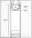
FIG. 1C is a schematic diagram that shows a shifting tool 122 that can engage the tubular assembly 116. Specifically, the shifting tool 122 can engage the moving tubular 120. Once engaged, the shifting tool 122 can translate the moving tubular 120 in a downhole direction relative to the stationary tubular 118. As mentioned above, the stationary tubular 118 is cemented in place. Therefore, when the shifting tool 122 translates the moving tubular 120 in the downhole direction, the stationary tubular 118 remains in place. Consequently, the translation of the moving tubular 120 exposes the soft material included in the stationary tubular 118.
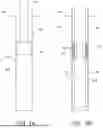
FIG. 2A is a schematic diagram that shows the stationary tubular 118 and the moving tubular 120 of the tubular assembly 116. When formed, the two tubulars of the tubular assembly 116 are joined by a mandrel 202 or similar component. For example, recesses can be formed in both respective tubulars. Ends of the mandrel 202 can be inserted into the recesses. The tubular assembly 116 can then be run into the primary wellbore 100. In this manner, the mandrel 202 maintains a connection between the stationary tubular 118 and the moving tubular 120 when the tubular assembly 116 is lowered into the primary wellbore 100.
FIG. 2B is a schematic diagram that shows the shifting tool 122 engaging the moving tubular 120 and moving the moving tubular 120 in a downhole direction. In some implementations, the moving tubular 120 defines an internal shifting profile 204, which includes grooves or recesses.
FIGS. 2C and 2D show a schematic of the latch profile 206. The latch profile 206 includes a top sub 208, an inner sleeve 210 and a bottom sub 212. The latch profile 206 has a female body in triangular shape.
FIG. 2E is a schematic diagram that shows the moving tubular 120 moved downhole by the shifting tool 122. To do so, a slack off is applied on the shifting tool 122. For example, a tension on the conveyance (e.g., a drill pipe, coiled tubing) used to run the shifting tool 122 into the primary wellbore 100 is decreased. The latch profile 206 is a female body with a triangular shape. The shifting tool 122 has a male profile in spring-loaded mode. Once the shifting tool 122 reaches the latch profile 206, the shifting tool 122 engages and latches the female body of the latch profile 206. A continued downward force then moves the tubular 120 in a downhole direction.
The shifting tool 122 then drops in a downhole direction. The latch profile 206 of the shifting tool 122 engages the internal shifting profile 204 of the moving tubular 120. The downhole movement of the shifting tool 122 applies a downhole force on the moving tubular 120. The mandrel 202, which holds the stationary tubular 118 and the moving tubular 120, is sheared under the downhole force on the moving tubular 120. The moving tubular 120 then translates in the downhole direction relative to the stationary tubular 118. The soft material of the stationary tubular 118 is consequently exposed to the interior of the primary wellbore 100.
Reference is now made to FIG. 1D, which is a schematic diagram that shows the exposed stationary tubular 118. After the shifting tool 122 moves the moving tubular 120 downhole within the primary wellbore 100, the stationary tubular 118, specifically the soft material of the stationary tubular 118, is exposed. The moving tubular 120 is part of the casing 112 and is placed between the soft material of the stationary tubular 118 and the casing 112. The motion path of the moving tubular 120 is in the space between the soft material and behind the casing wall.
Reference is now made to FIGS. 1E and 1F. As described above, the casing 112 is made up of multiple tubulars including an upper tubular 114a, a lower tubular 114b and a tubular assembly 116. The tubular assembly 116 includes the stationary tubular 116 and the moving tubular 120. The casing 112 is run into and installed (i.e., cemented) within the primary wellbore 100. The casing 112 is run into a depth such that the stationary tubular 118 is at a depth at which a window for a lateral wellbore is to be formed. That is, a downhole location from which the lateral wellbore is to be formed is pre-determined. The primary wellbore 100 is drilled at least past the determined downhole location of the lateral wellbore. The casing 112 is run into the primary wellbore 100 such that the stationary tubular 118 of the tubular assembly 116 is at the downhole location. Then, the shifting tool 122 is implemented as described above to expose the soft material of the stationary tubular 118 at the downhole location.
FIG. 1E is a schematic diagram that shows a bottom hole assembly (BHA) including a whipstock 124 that is run into the primary wellbore 100. The BHA, specifically the whipstock 124, is run in to a depth downhole of the stationary tubular 118. In some implementations, the BHA passes through the moving tubular 120 that is downhole of the stationary tubular 118. The BHA includes a packer 126 that is downhole of the whipstock 124. After the shifting tool 122 has been run out of the primary wellbore 100, the BHA with the whipstock 124 is run into the primary wellbore 100, and the packer 126 is set. A directional BHA 128 (e.g., a directional wellbore drilling assembly) can then be run into the primary wellbore 100.
FIG. 1F is a schematic diagram that shows the directional BHA 128 run into the primary wellbore 100. The whipstock 124 is oriented to guide the directional BHA 128 towards the stationary tubular 118. The directional BHA 128 includes a wellbore drilling assembly (including a wellbore drill bit) that can drill through the soft material of the stationary tubular 118 without being damaged. The directional BHA 128 can be operated to drill through the stationary tubular 118 and the cement that is in the annular space between the outer surface of the stationary tubular 118 and the inner wall of the primary wellbore 100. FIG. 1G is a schematic diagram that shows the directional BHA 128 drilling the lateral wellbore 130. The directional BHA 128 can further be operated to drill the lateral wellbore 130. In this manner and by using the tubular assembly 116 described here, the lateral wellbore 130 can be formed without using a milling assembly to mill a window in the casing 112.
FIG. 3 is a flowchart of an example of a process 300 of forming a lateral wellbore without using a milling assembly. At 302, a primary wellbore is formed. At 304, a portion of the primary wellbore is cased. The casing installed in the portion can include a tubular assembly (e.g., the tubular 116) with a moving tubular (e.g., the moving tubular 120) and a stationary tubular (e.g., the stationary tubular 118). The stationary tubular can include soft material as described above, e.g., material made of rubber.
At 306, the soft material of the stationary tubular can be exposed. To do so, a shifting tool (e.g., the shifting tool 122) can be run into the wellbore to engage with the moving tubular. A downhole slack off applies a force in a downhole direction on the moving tubular. The force causes the moving tubular to travel downhole relative to the stationary tubular. The relative movement exposes the soft material of the stationary tubular.
At 308, a whipstock is installed within the primary wellbore. For example, the whipstock (e.g., the whipstock 124) with a BHA can be lowered into the primary wellbore to a location downhole of the exposed stationary tubular. The whipstock can be oriented to guide a BHA toward the stationary tubular. In that orientation, the whipstock can be set.
At 310, the soft material is drilled through to form a window. To do so, a directional BHA (e.g., a directional wellbore drilling assembly) can be run into the primary wellbore. The whipstock guides the directional BHA towards the exposed soft material of the stationary tubular. The directional BHA drills through the soft material without any damage to the directional BHA.
At 312, a lateral wellbore is formed through the window. After drilling through the window, the directional BHA can continue to drill through the subterranean zone to form a lateral wellbore branching off the primary wellbore. In this manner, the lateral wellbore is formed without needing to use a milling assembly to drill a window in the casing installed in the primary wellbore.
In some implementations, the operations described here as being done in multiple trips can be combined into a single trip. For example, the shifting tool and the whipstock can be formed as a single BHA and run into the primary wellbore in a single trip. The BHA can be set by engaging the packer. Then, a downhole slack off can be applied on the shifting tool to expose the stationary tubular. The moving tubular can drop below the downhole location of the stationary tubular and further downhole of the whipstock. The moving tubular can be supported from further downhole movement by the packer. Then, the directional BHA can be run into the primary wellbore to drill through the soft material and to form the lateral wellbore, as described above.
EXAMPLES
Certain aspects of the subject matter described here can be implemented as a well tool assembly. The well tool assembly includes a tubular assembly that can be installed within a primary wellbore. The tubular assembly includes a stationary tubular including a wall. A portion of the wall is made of a soft material. The stationary tubular is formed as an outer layer of the tubular assembly. The tubular assembly includes a moving tubular formed as an inner layer of the tubular assembly. The moving tubular can translate relative to the stationary tubular to cover or expose the soft material. The well tool assembly includes a shifting tool that can engage the moving tubular and to translate the moving tubular relative to the stationary tubular until the soft material is exposed.
An aspect combinable with any other aspect includes the following features. The well tool assembly includes a whipstock that can be installed within the primary wellbore after the tubular assembly has been installed within the primary wellbore. The whipstock can form a lateral wellbore from the primary wellbore.
An aspect combinable with any other aspect includes the following features. The well tool assembly includes a wellbore drilling assembly that can be lowered into the primary wellbore after the whipstock has been installed within the primary wellbore.
An aspect combinable with any other aspect includes the following features. The whipstock is oriented to direct the wellbore drilling assembly toward the soft material. The wellbore drilling assembly can drill through the soft material to form the lateral wellbore.
An aspect combinable with any other aspect includes the following features. The moving tubular defines an internal shifting profile that can engage the shifting tool to translate relative to the stationary tubular.
An aspect combinable with any other aspect includes the following features. The shifting tool includes a latch profile that can engage the internal shifting profile of the moving tubular.
An aspect combinable with any other aspect includes the following features. The tubular assembly includes a mandrel that maintains a connection between the stationary tubular and the moving tubular when the tubular assembly is lowered into the primary wellbore.
An aspect combinable with any other aspect includes the following features. The tubular assembly includes a mandrel that maintains a connection between the stationary tubular and the moving tubular.
An aspect combinable with any other aspect includes the following features. The mandrel can be broken when the shifting tool engages the moving tubular and translates the moving tubular relative to the stationary tubular until the soft material is exposed.
An aspect combinable with any other aspect includes the following features. The soft material includes rubber.
Certain aspects of the subject matter described here can be implemented as a method. A primary wellbore is formed through a subterranean zone using a wellbore drilling assembly. At least a portion of the primary wellbore is cased. A whipstock is installed within the primary wellbore at a depth. Using the wellbore drilling assembly and the whipstock, and without using a milling assembly, a window is drilled through a side wall of the casing to form a lateral wellbore from the primary wellbore.
An aspect combinable with any other aspect includes the following features. To drill the window through the side wall of the casing using the wellbore drilling assembly and the whipstock stock and without using the milling assembly, a tubular assembly is run into the casing. The tubular assembly includes a stationary tubular including a wall. A portion of the wall is made of a soft material. The stationary tubular is formed as an outer layer of the tubular assembly. A moving tubular is formed as an inner layer of the tubular assembly. The moving tubular can translate relative to the stationary tubular to cover or expose the soft material. A shifting tool is run into the casing. The shifting tool engages the moving tubular. Using the shifting tool, the moving tubular is translated relative to the stationary tubular until the soft material is exposed.
An aspect combinable with any other aspect includes the following features. The moving tubular defines an internal shifting profile. To engage the moving tubular, the shifting tool engages the internal shifting profile of the moving tubular.
An aspect combinable with any other aspect includes the following features. The shifting tool includes a latch profile. To engage the internal shifting profile of the moving tubular, the latch profile of the shifting tool engages the internal shifting profile of the moving tubular. The shifting tool translates the moving tubular relative to the stationary tubular until the mandrel breaks.
An aspect combinable with any other aspect includes the following features. The soft material includes rubber.
Certain aspects of the subject matter described here can be implemented as a well tool assembly. The assembly includes a wellbore drilling assembly that can form a primary wellbore through a subterranean zone. The assembly includes a casing that can be installed within the primary wellbore. The assembly includes a bottom hole assembly that can be installed within the casing. The bottom hole assembly includes a whipstock that can be installed within the primary wellbore. The bottom hole assembly includes a tubular assembly that can be installed within a primary wellbore. The tubular assembly includes a stationary tubular including a wall. A portion of the wall is made of a soft material. The stationary tubular is formed as an outer layer of the tubular assembly. The tubular assembly includes a moving tubular formed as an inner layer of the tubular assembly. The moving tubular can translate relative to the stationary tubular to cover or expose the soft material. The well tool assembly includes a shifting tool that can engage the moving tubular and to translate the moving tubular relative to the stationary tubular until the soft material is exposed. The whipstock can guide the wellbore drilling assembly to drill through the soft material and to drill a lateral wellbore from the primary wellbore.
An aspect combinable with any other aspect includes the following features. The soft material includes rubber.
An aspect combinable with any other aspect includes the following features. The well tool assembly can form the lateral wellbore without a milling tool assembly.
Thus, particular embodiments of the subject matter have been described. Other embodiments are within the scope of the following claims.
Claims
1. A well tool assembly comprising:
a tubular assembly configured to be installed within a primary wellbore, the tubular assembly comprising:
a stationary tubular comprising a wall, a portion of the wall made of a soft material, the stationary tubular formed as an outer layer of the tubular assembly, and
a moving tubular formed as an inner layer of the tubular assembly, the moving tubular configured to translate relative to the stationary tubular to cover or expose the soft material; and
a shifting tool configured to engage the moving tubular and to translate the moving tubular relative to the stationary tubular until the soft material is exposed.
2. The well tool assembly of claim 1, further comprising a whipstock configured to be installed within the primary wellbore after the tubular assembly has been installed within the primary wellbore, the whipstock configured to form a lateral wellbore from the primary wellbore.
3. The well tool assembly of claim 2, further comprising a wellbore drilling assembly configured to be lowered into the primary wellbore after the whipstock has been installed within the primary wellbore.
4. The well tool assembly of claim 3, wherein the whipstock is oriented to direct the wellbore drilling assembly toward the soft material, wherein the wellbore drilling assembly is configured to drill through the soft material to form the lateral wellbore.
5. The well tool assembly of claim 1, wherein the moving tubular defines an internal shifting profile configured to engage the shifting tool to translate relative to the stationary tubular.
6. The well tool assembly of claim 5, wherein the shifting tool comprises a latch profile configured to engage the internal shifting profile of the moving tubular.
7. The well tool assembly of claim 1, wherein the tubular assembly comprises a mandrel that maintains a connection between the stationary tubular and the moving tubular when the tubular assembly is lowered into the primary wellbore.
8. The well tool assembly of claim 7, wherein the mandrel is configured to be broken when the shifting tool engages the moving tubular and translates the moving tubular relative to the stationary tubular until the soft material is exposed.
9. The well tool assembly of claim 1, wherein the soft material comprises rubber.
10. A method comprising:
forming a primary wellbore through a subterranean zone using a wellbore drilling assembly;
casing at least a portion of the primary wellbore;
installing a whipstock within the primary wellbore at a depth; and
using the wellbore drilling assembly and the whipstock, and without using a milling assembly, drilling a window through a side wall of the casing to form a lateral wellbore from the primary wellbore.
11. The method of claim 10, wherein using the wellbore drilling assembly and the whipstock, and without using the milling assembly, drilling the window through the side wall of the casing comprises:
running a tubular assembly into the primary wellbore, the tubular assembly comprising:
a stationary tubular comprising a wall, a portion of the wall made of a soft material, the stationary tubular formed as an outer layer of the tubular assembly, and
a moving tubular formed as an inner layer of the tubular assembly, the moving tubular configured to translate relative to the stationary tubular to cover or expose the soft material;
running a shifting tool into the casing;
engaging, by the shifting tool, the moving tubular;
translating, by the shifting tool, the moving tubular relative to the stationary tubular until the soft material is exposed.
12. The method of claim 11, wherein the moving tubular defines an internal shifting profile, wherein engaging, by the shifting tool, the moving tubular comprises engaging, by the shifting tool, the internal shifting profile of the moving tubular.
13. The method of claim 12, wherein the shifting tool comprises a latch profile, wherein engaging, by the shifting tool, the internal shifting profile of the moving tubular comprises engaging, by the latch profile of the shifting tool, the internal shifting profile of the moving tubular.
14. The method of claim 11, wherein the tubular assembly comprises a mandrel that maintains a connection between the stationary tubular and the moving tubular, wherein translating, by the shifting tool, the moving tubular relative to the stationary tubular comprises moving the moving tubular relative to the stationary tubular until the mandrel breaks.
15. The method of claim 11, wherein the soft material is rubber.
16. A well tool assembly comprising:
a wellbore drilling assembly configured to form a primary wellbore through a subterranean zone;
a casing configured to be installed within the primary wellbore;
a bottom hole assembly configured to be installed within the casing, the bottom hole assembly comprising:
a whipstock configured to be installed within the primary wellbore,
a tubular assembly configured to be installed within a primary wellbore formed by the wellbore drilling assembly, the tubular assembly comprising:
a stationary tubular comprising a wall, a portion of the wall made of a soft material, the stationary tubular formed as an outer layer of the tubular assembly, and
a moving tubular formed as an inner layer of the tubular assembly, the moving tubular configured to translate relative to the stationary tubular to cover or expose the soft material; and
a shifting tool configured to engage the moving tubular and to translate the moving tubular relative to the stationary tubular until the soft material is exposed, wherein the whipstock is configured to guide the wellbore drilling assembly to drill through the soft material and to drill a lateral wellbore from the primary wellbore.
17. The well tool assembly of claim 16, wherein the soft material comprises rubber.
18. The well tool assembly of claim 16, wherein the well tool assembly is configured to form the lateral wellbore without a milling tool assembly.
Images & Drawings included:


Sources:
- United States Patent and Trademark Office - verify current appl. status at the USPTO↗
Recent applications in this class:
- » 20250270889 2025-08-28
Milling and Collecting Debris in Depleted or Sub-Hydrostatic Wells - » 20240418050 2024-12-19
Method and system for simultaneous wireline milling and debris collection - » 20230098383 2023-03-30
Force dissipation assembly for use with disconnect tools - » 20220018200 2022-01-20
Separable housing assembly for tubular control conduits - » 20210404278 2021-12-30
Impact-triggered floatation tool - » 20210363846 2021-11-25
Integrated milling and production device - » 20210355778 2021-11-18
Or relating to well abandonment and slot recovery - » 20210348464 2021-11-11
Annulus cement breaker - » 20210238942 2021-08-05
Degradable in-line buoyant system for running casing in a wellbore - » 20210108476 2021-04-15
Holding and crushing device for barrier plug