GOLF CLUB ALIGNMENT SYSTEM AND METHOD
US20260021353A1
2026-01-22
19/341,339
2025-09-26
Smart Summary: A golf club alignment system helps golfers aim their shots more accurately. It uses a detachable device that attaches to the back of the club head and projects a beam to show the target direction. Golfers can choose from different alignment plates that have various markings and colors to suit their preferences. For indoor practice, the system projects a line on the ground, while for outdoor use, it shows a dot on a backdrop. A method is included to help users find the best alignment plate by testing different colors and shapes for accuracy. 🚀 TL;DR
Abstract:
A golf club alignment system integrates a detachable alignment device with a visual aid emitter and a club head interface that accepts interchangeable alignment plates with alignment markings. The device mounts to the face backside and references the topline to emit a beam that indicates target direction. The plates provide centerlines and optional shapes in chromatic or monochromatic schemes so a user can select markings that match personal visual preference. An indoor device projects a line on a surface and an outdoor device projects a dot on a portable backdrop. A diagnostic method guides selection by comparing accuracy with different color classes and with line only or shape inclusive markings and then choosing the preferred plate based on measured results.
Inventors:
- Vikash Sanyal 12 🇺🇸 Valley Center, CA, United States
- Andre Shmoldas 3 🇺🇸 Carlsbad, CA, United States
Assignee:
- The Chamber LLC 1 🇺🇸 Valley Center, CA, United States
Applicant:
Interested in similar patents?
Get notified when new applications in this technology area are published.
Classification:
A63B53/0441 » CPC main
Golf clubs; Heads with visual indicators for aligning the golf club
A63B2209/08 » CPC further
Characteristics of used materials magnetic
A63B2225/74 » CPC further
Miscellaneous features of sport apparatus, devices or equipment with powered illuminating means, e.g. lights
A63B53/04 IPC
Golf clubs Heads
Description
CROSS-REFERENCE TO RELATED APPLICATIONS
This application is a continuation-in-part (CIP) with U.S. Non-provisional application Ser. No. 18/624,723, filed Apr. 2, 2024; the entire contents of which are hereby incorporated by reference.
This application is a continuation-in-part (CIP) with U.S. Non-provisional application Ser. No. 18/696,832, filed Dec. 5, 2024; the entire contents of which are hereby incorporated by reference.
BACKGROUND
Field of the Invention
This invention relates to a golf alignment system; more particularly, a golf alignment system comprising a visual aid emitter and one or more alignment plates.
Description of the Related Art
Proper clubface alignment at address is a primary determinant of starting line and directional control, yet many golfers struggle to aim consistently because the visual cues that guide alignment are highly individual. Conventional aids often rely on fixed sight lines or uniform markings on a putter head or mat and do not adapt to a user's personal visual tendency. Many lack an active aim indicator referenced to the club's topline and face, and they rarely offer a structured way to discover which visual scheme a given golfer reads most accurately. As a result, users cannot systematically select markings that match their perception or switch between indoor and outdoor practice contexts with equal effectiveness, leaving performance gains unrealized.
SUMMARY
The invention is a golf club alignment system that unites a detachable alignment device with a plate-ready interface on the club head to provide both active and passive aim references. The head includes a flange-defined alignment deck with a receiving mechanism and a topline notch that orients the device, while the alignment device having a visual aid emitter emits a beam and transmits over the topline to indicate target direction. Interchangeable alignment plates comprise alignment markings, such as centerlines and optional shape, that cooperate with the beam for clear, repeatable setup. This architecture is illustrated with a putter but is applicable to wedges, irons, and woods, and may be implemented with laser, LED, or reflective visual aids.
Complementing the hardware, a diagnostic method guides selection of a golfer-specific plate by empirically determining visual preference. The golfer first compares chromatic versus monochromatic centerlines to establish a preferred color class, then compares line-only plates versus plates with geometric shaped markings, such as circle or triangle, within that class, selecting the plate that yields higher measured accuracy. The method can be repeated over time to account for changes in the golfer's visual tendency.
BRIEF DESCRIPTION OF THE DRAWINGS
Other features, combinations, and embodiments will be appreciated by one having the ordinary level of skill in the art of golf and accessories upon a thorough review of the following details and descriptions, particularly when reviewed in conjunction with the drawings, wherein:
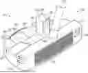
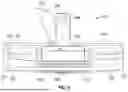
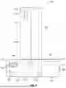
FIG. 1 shows a front perspective view of a club alignment system in accordance with a first illustrated embodiment;
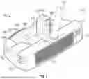
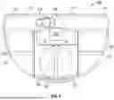
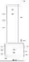
FIG. 2 show a rear perspective view of the club alignment system according to the first illustrated embodiment;
FIG. 3 shows a front view of the club alignment system according to the first illustrated embodiment;
FIG. 4 shows a rear view of the club alignment system according to the first illustrated embodiment;
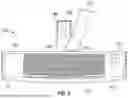
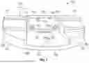
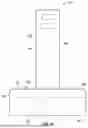
FIG. 5 shows a top view of the club alignment system according to the first illustrated embodiment;
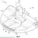
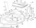
FIG. 6 shows an exploded view of the club alignment system according to the first illustrated embodiment;
FIG. 7 shows a rear view of a golf club head according to the first illustrated embodiment;
FIG. 8 shows a front perspective view of an alignment device according to the first illustrated embodiment;
FIG. 9 shows a side view of the alignment device according to the first illustrated embodiment;
FIG. 10 shows a rear view of the alignment device according to the first illustrated embodiment;
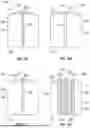
FIG. 11A shows a top view of a first alignment plate in accordance with a second illustrated embodiment;
FIG. 11B shows a top view of a second alignment plate according to the second illustrated embodiment;
FIG. 11C shows a top view of a third alignment plate according to the second illustrated embodiment;
FIG. 11D shows a top view of a fourth alignment plate according to the second illustrated embodiment;
FIG. 12A shows a top view of a fifth alignment plate according to the second illustrated embodiment;
FIG. 12B shows a top view of a sixth alignment plate according to the second illustrated embodiment;
FIG. 12C shows a top view of a seventh alignment plate according to the second illustrated embodiment;
FIG. 12D shows a top view of a eight alignment plate according to the second illustrated embodiment;
FIG. 13 shows a bottom view of an alignment plate according to the second illustrated embodiment;
FIG. 14 shows a flowchart of a diagnostic method determining a golfer's personal visual tendency with respect to alignment markings in accordance with a third embodiment;
FIG. 15A shows a front view of an indoor laser module in accordance with a fourth illustrated embodiment;
FIG. 15B shows a front view of an outdoor laser module according to the fourth illustrated embodiment; and
FIG. 16 shows a rear view of the club alignment system according to the fourth illustrated embodiment.
DETAILED DESCRIPTION
For purposes of explanation and not limitation, details and descriptions of certain preferred embodiments are hereinafter provided such that one having ordinary skill in the art may be enabled to make and use the invention. These details and descriptions are representative only of certain preferred embodiments, however, a myriad of other embodiments which will not be expressly described will be readily understood by one having skill in the art upon a thorough review of the instant disclosure. Accordingly, any reviewer of the instant disclosure should interpret the scope of the invention only by the claims, as such scope is not intended to be limited by the embodiments described and illustrated herein.
The features, components, and configurations described in connection with the various embodiments illustrated herein may be combined, interchanged, or otherwise modified in any number of ways without departing from the scope and spirit of the invention. The embodiments are presented by way of example and not limitation, and it is intended that the invention encompasses all such combinations, permutations, and modifications as would be understood by those skilled in the art.
For purposes herein, the term “monochromatic” means having color (not black or white).
The term “chromatic” means being black or white with no color.
The term “geometric” means lines shapes.
Unless explicitly defined herein, terms are to be construed in accordance with the plain and ordinary meaning as would be appreciated by one having skill in the art.
GENERAL DESCRIPTION OF EMBODIMENTS
In a general embodiment, a golf club alignment system is disclosed. The system may comprise a golf club having a head coupled to a shaft, the head having a face configured to contact a golf ball, a face backside opposite the face with one or more positioning recesses, a topline disposed between the face and the face backside with a notch, and a flange extending from the face backside that may include an alignment deck. The system may further comprise an alignment device configured to detachably couple to the head of the golf club at the face backside and the alignment deck, the alignment device being configured to engage with the notch. The alignment device may comprise a visual aid emitter configured to transmit over the topline of the head, which may comprise a laser module, a magnetic subcomponent configured to magnetically engage the face backside, and a device housing having a front side and a back side opposite the front side, with the visual aid emitter disposed on the front side. The device housing may further include one or more positioning standoffs disposed on the front side and aligned with the positioning recesses for engagement therewith, and a charging portion disposed on the front side. The system may also comprise a plurality of alignment plates, each configured to detachably couple to the head at the alignment deck. Each alignment plate may comprise a top surface and a bottom surface opposite the top surface, alignment markings disposed on the top surface, a proximal end configured to be disposed closer to the face than a distal end, and a centerline extending from the distal end to the proximal end, which may comprise either a chromatic centerline or a monochromatic centerline. An attached alignment plate may be disposed between the alignment deck and the alignment device. One or more of the alignment plates may further include shaped markings disposed on the top surface at the distal end, which may comprise either a monochromatic shaped marking or a chromatic shaped marking.
In some embodiments, the alignment device may further comprise an actuator disposed on the back side, the actuator being configured to select power modes and lighting modes.
In some embodiments, the device housing may further comprise a mode indicator configured to provide a visual indication to a golfer.
In some embodiments, the device housing may further comprise a base segment and an elongated extension projecting upward from the base segment, where the base segment may be configured to engage with the face backside and the elongated extension may extend above the topline.
In some embodiments, the elongated extension may project from a base top side of the base segment, with the base top side including a mode indicator configured to provide a visual indication to a golfer.
In some embodiments, the shaped markings may comprise a circle or a triangle.
In some embodiments, the centerline may bisect the shaped markings.
In some embodiments, one or more of the alignment plates may comprise a monochromatic shaped marking bisected by a chromatic centerline, and one or more of the alignment plates may comprise a chromatic shaped marking bisected by a monochromatic centerline.
In some embodiments, one or more of the alignment plates may comprise a plurality of parallel lines flanking either the chromatic centerline or the monochromatic centerline.
In some embodiments, the system may further comprise a plurality of alignment devices, including an indoor laser module and an outdoor laser module, wherein the indoor laser module may comprise a line-generating planar beam and the outdoor laser module may comprise a dot-generating point beam.
In some embodiments, the outdoor laser module may have a first height and the indoor laser module may have a second height, with the first height being greater than the second height.
In some embodiments, the system may further comprise an alignment backdrop configured to receive either the line-generating planar beam or the dot-generating point beam.
In another general embodiment, a golf club alignment system is disclosed. The system may comprise a golf club having a head coupled to a shaft, the head comprising a face configured to contact a golf ball, a face backside opposite the face, and a topline disposed between the face and the face backside. The system may further comprise an alignment device configured to detachably couple to the face backside, the alignment device comprising a visual aid emitter configured to transmit over the topline of the head.
In some embodiments, the alignment device may further comprise a magnetic subcomponent configured to magnetically engage the face backside.
In some embodiments, the alignment device may further comprise a laser module.
In some embodiments, the alignment device may further comprise a device housing having a front side and a back side opposite the front side, with the visual aid emitter disposed on the front side.
In some embodiments, the alignment device may further comprise one or more positioning standoffs disposed on the front side, and the face backside may further comprise one or more positioning recesses aligned for receiving the positioning standoffs.
In some embodiments, the alignment device may further comprise a charging port disposed on the front side.
In some embodiments, the alignment device may further comprise an actuator disposed on the back side, the actuator being configured to select power modes and lighting modes.
In some embodiments, the device housing may further comprise a mode indicator configured to provide a visual indication to a golfer.
In some embodiments, the device housing may further comprise a base segment and an elongated extension projecting upward from the base segment, wherein the base segment may engage with the face backside and the elongated extension may extend above the topline.
In some embodiments, the topline may further comprise a notch configured to engage with the front side of the elongated extension.
In some embodiments, the elongated extension may project from a base top side of the base segment, with the base top side including a mode indicator configured to provide a visual indication to a golfer.
In some embodiments, the topline may further comprise a notch configured to engage with the alignment device.
In some embodiments, the head may further comprise a flange extending from the face backside, the flange including an alignment deck where the alignment device may be disposed.
In some embodiments, the system may further comprise an alignment plate configured to detachably couple to the head, the alignment plate including alignment markings.
In some embodiments, the alignment plate may be configured to detachably couple to the flange of the head.
In some embodiments, the alignment plate may be configured to detachably couple to the alignment deck.
In some embodiments, the alignment plate may be disposed between the alignment device and the alignment deck.
In some embodiments, the alignment plate may comprise a top surface and a bottom surface opposite the top surface, with alignment markings disposed on the top surface. The alignment plate may further comprise a proximal end and a distal end opposite the proximal end, the proximal end being configured to be disposed closer to the face than the distal end.
In some embodiments, the alignment markings may further comprise a centerline extending from the proximal end to the distal end.
In some embodiments, the centerline may further comprise either a chromatic centerline or a monochromatic centerline.
In some embodiments, the alignment markings may further comprise shaped markings disposed on the top surface at the distal end.
In some embodiments, the shaped markings may comprise a circle or a triangle.
In some embodiments, the centerline may bisect the shaped markings.
In some embodiments, the shaped markings may comprise either a chromatic shape or a monochromatic shape.
In some embodiments, the system may further comprise a plurality of alignment plates configured to detachably couple to the head, including one or more alignment plates comprising a chromatic centerline and one or more alignment plates comprising a monochromatic centerline.
In some embodiments, one or more of the alignment plates may comprise a monochromatic shaped marking bisected by a chromatic centerline, and one or more of the alignment plates may comprise a chromatic shaped marking bisected by a monochromatic centerline.
In some embodiments, one or more of the alignment plates may comprise a plurality of parallel lines flanking either the chromatic centerline or the monochromatic centerline.
In some embodiments, the system may further comprise a plurality of alignment devices including an indoor laser module and an outdoor laser module, wherein the indoor laser module may comprise a line-generating planar beam and the outdoor laser module may comprise a dot-generating point beam.
In some embodiments, the outdoor laser module may have a first height and the indoor laser module may have a second height, with the first height being greater than the second height.
In some embodiments, the system may further comprise an alignment backdrop configured to receive either the line-generating planar beam or the dot-generating point beam.
In another general embodiment, a diagnostic method for determining a golfer's visual alignment preference using alignment plates is disclosed. The method may comprise coupling a first color alignment plate to a head of a golf club, the first color alignment plate having a monochromatic centerline, and testing accuracy of the first color alignment plate. A second color alignment plate may then be coupled to the head of the golf club, the second color alignment plate having a chromatic centerline, and the accuracy of the second color alignment plate may be tested. The method may include comparing the accuracy of the first and second color alignment plates, and selecting a preferred color based on which plate provides higher accuracy. The method may further comprise coupling a first geometric alignment plate to the head of the golf club, the first geometric alignment plate having a centerline of the preferred color, and testing the accuracy of the first geometric alignment plate. A second geometric alignment plate may then be coupled to the head of the golf club, the second geometric alignment plate having a shaped marking of the preferred color, and the accuracy of the second geometric alignment plate may be tested. The method may include comparing the accuracy of the first and second geometric alignment plates, and selecting a preferred alignment plate comprising a preferred geometric marking based on higher accuracy, with the preferred geometric marking having the preferred color.
In some embodiments, the shaped marking may comprise a circle marking or a triangle marking.
In some embodiments, the method may further comprise coupling and testing a third geometric alignment plate, wherein the second geometric alignment plate may comprise a circle marking and the third geometric alignment plate may comprise a triangle marking.
In some embodiments, the second geometric alignment plate may further comprise a centerline bisecting the shaped marking, with the centerline comprising an inverse of the preferred color.
In some embodiments, the first geometric alignment plate may be either the first color alignment plate or the second color alignment plate.
Each of the components of alignment device, alignment plates, and related system described herein may be manufactured and/or assembled in accordance with the conventional knowledge and level of a person having skill in the art.
While various details, features, combinations are described in the illustrated embodiments, one having skill in the art will appreciate a myriad of possible alternative combinations and arrangements of the features disclosed herein. As such, the descriptions are intended to be enabling only, and non-limiting. Instead, the spirit and scope of the invention is set forth in the appended claims.
First Illustrated Embodiment
Now turning to the drawings, FIGS. 1-10 show the golf club alignment system according to the first embodiment. The golf club alignment system (100) comprises a golf club (110), an alignment device (140), and an alignment plate (160). Each of the alignment device (140) and the alignment plate (160) are configured to detachably couple to a head (111) of the golf club (110). In some configurations, the club alignment system (100) includes the golf club (110) together with only the alignment device (140) or together with only the alignment plate (160). The golf club alignment system (100) is configured to assist a golfer in achieving proper alignment toward a target by providing visual references on the alignment plate (160) and by projecting a visual aid from the alignment device (140) that is oriented with a face (113) of the head (111) along an intended ball-travel path. The golf club (110) comprises a shaft (112) coupled to the head (111) at a hosel (116), the head (111) including the face (113) configured to contact a golf ball, a face backside (114) opposite the face (113), a sole (115), and a topline (117) disposed between the face (113) and the face backside (114). The topline (117) includes a topline shelf (118) extending over the face backside (114) to form a rear cavity (120) between the topline shelf (118) and the face backside (114). The head (111) further comprises a flange (130) extending from the face backside (114), the flange (130) including side rails (131) that define an alignment deck (132) configured to receive the alignment plate (160). The alignment deck (132) incorporates a receiving mechanism (133) that, in the illustrated form, comprises a registration slot (135) and an aperture (134) extending through the flange (130) and the sole (115) to facilitate detachable coupling of the alignment plate (160) as described for other embodiments. The head (111) additionally comprises one or more positioning recesses (121) on the face backside (114) to mate with complementary structure of the alignment device (140) for repeatable positioning.
The alignment device (140) comprises a device housing (142) having a front side (145) and a back side (146), a base segment (143) configured to engage the face backside (114), and an elongated extension (144) projecting upward from a base top side (147) of the base segment (143). A visual aid emitter (150) is disposed on the elongated extension (144) at the front side (145) and is configured to be at a higher elevation than the topline (117) such that the visual aid emitter (150) can emit a beam or transmit over the topline (117) in a direction generally parallel to the face (113); in the illustrated form, the visual aid emitter (150) comprises a laser module (141) controlled by a microcontroller (151) powered by a battery (152) within the device housing (142). The alignment device (140) further comprises an actuator (154) on the back side (146) for selecting power and lighting modes and a mode indicator (155) on the base top side (147) for providing visual feedback, including signaling an imminent transition to an emission state; the alignment device (140) also comprises a charging port (153) disposed on the front side (145) of the base segment (143) such that when the alignment device (140) is coupled to the head (111) the face backside (114) shields the charging port (153) from dirt and moisture. The alignment device (140) further comprises a magnetic subcomponent (156) positioned within the base segment (143) to magnetically engage the face backside (114), and one or more positioning standoffs (157) on the front side (145) that are aligned with, and configured to seat within, the positioning recesses (121) of the face backside (114) to provide anti-skew registry and retention of the alignment device (140). The topline (117) includes a notch (122) configured to engage the front side (145) of the elongated extension (144) so that the notch (122) cooperatively keys the alignment device (140) for consistent angular orientation with respect to the topline (117), while still permitting easy detachment of the alignment device (140).
In operation, the alignment device (140) is configured to emit a laser from the visual aid emitter (150) over the topline (117) in a continuous mode or in one or more intermittent modes to provide alignment feedback to the golfer. In one representative intermittent mode, the alignment device (140) remains off for a delay interval to allow address setup and the mode indicator (155) flashes to warn that emission is imminent before the visual aid emitter (150) turns on for a shorter feedback interval, after which the cycle repeats. While lasers are illustrated, alternative visual-aid technologies may be employed to achieve functionally analogous alignment feedback, including guided light from LED sources, reflective markers responsive to external light, or integration with augmented-reality systems. Such alternatives may be implemented within or on the device housing (142) without departure from the functional role of the alignment device (140). The device housing (142) can be fabricated using conventional manufacturing techniques, including molding or machining of polymeric or metallic materials, with the magnetic subcomponent (156) selected from common permanent magnet types and the laser module (141) packaged behind a protective window; fasteners, adhesives, or integral features may be used internally as is standard practice in small electro-mechanical assemblies, while external mounting remains detachably magneto-mechanical as described above. The golf club (110) is depicted as a putter for clarity of the views, but the golf club alignment system (100) is also applicable to other club types, including wedges, irons, and woods, without changing the function or relationship of the alignment device (140) and the alignment plate (160).
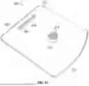
The alignment plate (160) is configured to detachably couple to the alignment deck (132) and includes a top surface (161) and a bottom surface (162) opposite the top surface (161). Alignment markings (163) are disposed on the top surface (161) to provide visual guides for aiming the face (113) with respect to a target, and include a centerline (164) that can be chromatic or monochromatic so that the centerline (164) is readily perceived under expected lighting conditions. The centerline (164) is aligned with the notch (122) of the topline (117) and with the visual aid emitter (150) when the alignment device (140) is coupled to the head (111). In some configurations, the alignment device (140) rests above the alignment plate (160) so that the base segment (143) contacts the top surface (161), while in other configurations the alignment plate (160) is shortened so that the base segment (143) directly contacts the alignment deck (132) to facilitate faster plate changes while the alignment device (140) remains engaged to the head (111). The bottom surface (162) is configured to engage the receiving mechanism (133) of the alignment deck (132) for detachable coupling consistent with the usage described for other embodiments.
Second Illustrated Embodiment
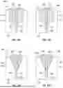
FIGS. 11A-13 show the golf club alignment system according to the second embodiment. A plurality of alignment plates (200) are provided, including a first alignment plate (201), a second alignment plate (202), a third alignment plate (203), a fourth alignment plate (204), a fifth alignment plate (205), a sixth alignment plate (206), a seventh alignment plate (207), and an eighth alignment plate (208). Each alignment plate comprises a top surface (210) and a bottom surface (211) opposite the top surface (210), a proximal end (212) and an opposite distal end (213), and alignment markings (220) on the top surface (210) configured to guide aim. Each alignment plate includes a centerline (221) extending from the proximal end (212) toward the distal end (213), where the centerline (221) is, in different examples, a chromatic centerline (222) or a monochromatic centerline (223). In certain versions, the alignment markings (220) further include a plurality of parallel lines (224) comprising at least one monochromatic line (225) and at least one chromatic line (226). The bottom surface (211) includes a coupling mechanism (214) configured for detachable attachment to the flange (130; FIG. 6), the coupling mechanism (214) in the illustrated form including a post (215) configured to engage the aperture (134: FIG. 6) and a registration tab (216) configured to engage the registration slot (135; FIG. 6) of the receiving mechanism (133; FIG. 6) of the alignment deck (132) described with the first embodiment, thereby ensuring repeatable and secure positioning on the golf club head while still allowing rapid interchange among the plurality of alignment plates (200).
Across the plurality of alignment plates (200), certain alignment plates employ only the centerline (221) without shaped markings, whereas other alignment plates employ shaped markings at or near the distal end (213). Shaped markings may include a chromatic shape (227) such as a chromatic circle (228) or a chromatic triangle (229), or a monochromatic shape (230) such as a monochromatic circle (231) or a monochromatic triangle (232). In plates that include both a centerline (221) and a shaped marking, one of the centerline (221) or the shaped marking is chromatic and the other is monochromatic such that the colors are inverses in the sense of chromatic versus monochromatic to create a consistent, high-contrast visual pairing that emphasizes the intended alignment reference.
By way of example, the first alignment plate (201) presents a chromatic centerline (222) serving as the sole alignment marking, devoid of shaped markings, with the chromatic centerline (222) represented in the figures as red for high salience on the top surface (210). The second alignment plate (202) presents a monochromatic centerline (223) as the sole alignment marking on a contrasting top surface (210) to enhance visibility of the monochromatic centerline (223). The third alignment plate (203) presents a monochromatic centerline (223) that is white on the top surface (210) to provide a different luminance cue for users whose visual preference leans toward higher brightness contrast. The fourth alignment plate (204) presents a chromatic centerline (222) with the alignment markings (220) further comprising the plurality of parallel lines (224) in which the chromatic centerline (222) is disposed between two monochromatic lines (225) and each of the monochromatic lines (225) is flanked by a chromatic line (226), thereby forming a multi-line lane that visually guides the face (113: FIG. 1) toward the intended path and that interacts with the beam.
Further examples illustrate shaped-marking plates that combine line and shape cues. The fifth alignment plate (205) presents a monochromatic centerline (223) that bisects a chromatic shape (227), here a red circle as the chromatic circle (228) placed near the distal end (213), so that the monochromatic centerline (223) and the chromatic circle (228) cooperate to indicate both direction and face centering during address. The sixth alignment plate (206) presents a chromatic centerline (222) that bisects a monochromatic shape (230), here a white circle as the monochromatic circle (231) near the distal end (213), reversing the color roles to accommodate golfers whose visual tendency favors a colored linear cue. The seventh alignment plate (207) presents a monochromatic centerline (223) that bisects a chromatic shape (227), here a red triangle as the chromatic triangle (229) with a base at the distal end (213) and an apex pointing toward the proximal end (212), thereby generating a directional arrow cue in combination with the monochromatic centerline (223). The eighth alignment plate (208) presents a chromatic centerline (222) that bisects a monochromatic shape (230), here a white triangle as the monochromatic triangle (232) disposed with a base at the distal end (213) and an apex toward the proximal end (212), creating a complementary directional scheme that preserves the chromatic and monochromatic inverse pairing set forth above. In each case, the centerline (221) is intended to be collinear with the notch (122; FIG. 6) and with the beam from the visual aid emitter (150; FIG. 1) when the alignment device (140: FIG. 1) is used.
Third Illustrated Embodiment
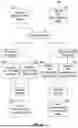
FIG. 14 shows a diagnostic method according to the third embodiment. The diagnostic method (300) is configured to determine a golfer's personal visual tendency with respect to alignment markings by comparing performance with chromatic versus monochromatic cues and with line-only versus shape-inclusive cues, and then selecting a preferred alignment plate from the plurality of alignment plates that matches the golfer's tendency. In one aspect, Steps 1A (310) and 1B (315) involve coupling and testing alignment plates from the plurality of alignment plates that respectively provide chromatic centerlines and monochromatic centerlines, and comparing the resulting accuracy so that a preferred color class is identified; consistent with the usage herein, “inverse” is treated as chromatic versus monochromatic rather than complementary hues, such that if a shaped marking is chromatic then the bisecting centerline is monochromatic, and vice versa. If a chromatic preference is identified, Steps 2A (320) and 2B (325) involve testing alignment plates that respectively employ chromatic line-only markings and chromatic shaped markings, for example by comparing an alignment plate having the chromatic centerline only with an alignment plate having the chromatic circle or the chromatic triangle bisected by the chromatic centerline, and Step 3 (330) then selects the preferred chromatic plate based on higher measured accuracy. If a monochromatic preference is identified, Steps 4A (340) and 4B (345) involve testing alignment plates that respectively employ monochromatic line-only markings and monochromatic shaped markings, for example by comparing an alignment plate having the monochromatic centerline only with an alignment plate having the monochromatic circle or the monochromatic triangle bisected by the monochromatic centerline, and Step 5 (350) then selects the preferred monochromatic plate based on higher measured accuracy. The order of the diagnostic method (300) can vary without departing from its function, and in certain implementations individual plates of the plurality of alignment plates are tested and compared against all others. The diagnostic method (300) can be repeated over time to account for changes in the golfer's visual alignment preference.
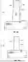
FIGS. 15A-16 show the golf club alignment system according to the fourth embodiment. In this embodiment the club alignment system (400) is implemented with distinct devices optimized for indoor and outdoor use. An indoor laser module (401) is configured to emit a line-generating planar beam (403) and is further configured with a first height (402) sufficient to elevate the line-generating planar beam (403) above the topline so that the line-generating planar beam (403) intersects a ground surface in front of the face and produces a visible reference line under indoor lighting; conversely, an outdoor laser module (404) is configured to emit a dot-generating point beam (406) and is further configured with a second height (405) that is less than the first height (402) because the dot-generating point beam (406) is projected directly forward and remains visible as a laser dot (430) under outdoor daylight conditions without requiring a ground-plane line. The modules are shown as distinct devices rather than swappable cartridges, although other embodiments can implement swappable modules without changing the basic operation described here. In an outdoor use case, a golf club (410) is used together with an alignment device (440) and, optionally, an alignment plate (460), the alignment device (440) being detachably coupled to the golf club (410) and configured to project the dot-generating point beam (406) so that the laser dot (430) is received on an alignment backdrop (420), which can be realized as a freestanding, collapsible target such as a triangular-prism stand for convenient setup and takedown; in an indoor use case, the indoor laser module (401) projects the line-generating planar beam (403) so that a line is formed on the practice surface to provide a persistent path reference. Both the indoor laser module (401) and the outdoor laser module (404) are configured to emit a beam or to transmit over the topline in the direction of the face, consistent with the device-level description, and both operate within the general system context described in connection with the first embodiment so that the same alignment concepts apply across environments.
FEATURE LIST
-
- club alignment system (100; 400)
- golf club (110; 410)
- head (111)
- shaft (112)
- face (113)
- face backside (114)
- sole (115)
- hosel (116)
- topline (117)
- topline shelf (118)
- rear cavity (120)
- positioning recess (121)
- notch (122)
- flange (130)
- side rail (131)
- alignment deck (132)
- receiving mechanism (133)
- aperture (134)
- registration slot (135)
- alignment device (140; 440)
- laser module (141)
- device housing (142)
- base segment (143)
- elongated extension (144)
- front side (145)
- back side (146)
- base top side (147)
- visual aid emitter (150)
- microcontroller (151)
- battery (152)
- charging port (153)
- actuator (154)
- mode indicator (155)
- magnetic subcomponent (156)
- positioning standoff (157)
- alignment plate (160; 460)
- top surface (161; 210)
- bottom surface (162; 211)
- alignment markings (163)
- centerline (164)
- plurality of alignment plate (200)
- first alignment plate (201)
- second alignment plate (202)
- third alignment plate (203)
- fourth alignment plate (204)
- fifth alignment plate (205)
- sixth alignment plate (206)
- seventh alignment plate (207)
- eight alignment plate (208)
- proximal end (212)
- distal end (213)
- coupling mechanism (214)
- post (215)
- registration tab (216)
- alignment markings (220)
- centerline (221)
- chromatic centerline (222)
- monochromatic centerline (223)
- plurality of parallel lines (224)
- monochromatic line (225)
- chromatic line (226)
- chromatic shape (227)
- chromatic circle (228)
- chromatic triangle (229)
- monochromatic shape (230)
- monochromatic circle (231)
- monochromatic triangle (232)
- indoor laser module (401)
- first height (402)
- line-generating planar beam (403)
- outdoor laser module (404)
- second height (405)
- dot-generating point beam (406)
- alignment backdrop (420)
- laser dot (430)
Claims
What is claimed is:1. A golf club alignment system, comprising:
a golf club comprising:
a head coupled to a shaft, the head comprising a face configured to contact a golf ball,
a face backside opposite the face, the face backside comprising one or more positioning recesses,
a topline disposed between the face and the face backside, the topline comprising a notch,
a flange extending from the face backside, the flange comprising an alignment deck;
an alignment device configured to detachably couple to the head of the golf club at face backside and the alignment deck, the alignment device configured to engage with the notch, the alignment device comprising:
a visual aid emitter configured to transmit over the topline of the head, wherein the visual aid emitter comprises a laser module,
a magnetic subcomponent configured to magnetically engage the face backside,
a device housing having a front side and a back side opposite the front side, wherein the visual aid emitter is disposed on the front side,
one or more positioning standoffs disposed on the front side, the one or more positioning standoffs aligned with the one or more positioning recesses for engagement therewith,
a charging portion disposed on the front side; and
a plurality of alignment plates, each of the plurality of alignment plates configured to detachably couple to the head at the alignment deck, each of the plurality of alignment plates comprising:
a top surface and a bottom surface opposite the top surface,
alignment markings disposed on the top surface,
a proximal end and a distal end opposite the proximal end, the proximal end configured to be disposed closer to the face than the distal end,
a centerline extending from the distal end to the proximal end, the centerline comprising one of a chromatic centerline or a monochromatic centerline,
wherein an attached alignment plate coupled to the golf club is disposed between the alignment deck and the alignment device,
further wherein one or more of the plurality of alignment plates comprise shaped markings disposed on the top surface at the distal end, each of the shaped markings comprise one of a monochromatic shaped marking or a chromatic shaped marking.
2. A golf club alignment system, comprising:
a golf club comprising a head coupled to a shaft, the head comprising a face configured to contact a golf ball, a face backside opposite the face, and a topline disposed between the face and the face backside; and
an alignment device configured to detachably couple to the face backside, the alignment device comprising a visual aid emitter configured to transmit over the topline of the head, the alignment device further comprising a device housing having a front side and a back side opposite the front side, wherein the visual aid emitter is disposed on the front side.
3. The golf club alignment system of claim 2, the alignment device further comprising a magnetic subcomponent configured to magnetically engage the face backside.
4. The golf club alignment system of claim 2, the alignment device further comprising a laser module.
5. The golf club alignment system of claim 2, the alignment device further comprising one or more positioning standoffs disposed on the front side and the face backside further comprising one or more positioning recesses aligned for receiving the one or more positioning standoffs.
6. The golf club alignment system of claim 2, the device housing further comprising a base segment and an elongated extension projecting upward from the base segment, wherein the base segment is configured to engage with the face backside and the elongated extension is configured to extend above the topline.
7. The golf club alignment system of claim 6, the topline further comprising a notch configured to engage with the front side of the elongated extension.
8. The golf club alignment system of claim 2, the topline further comprising a notch configured to engage with the alignment device.
9. The golf club alignment system of claim 2, the head further comprising a flange extending from the face backside, the flange comprising an alignment deck wherein the alignment device is disposed on top of the alignment deck.
10. The golf club alignment system of claim 9, further comprising an alignment plate configured to detachably couple to the head, the alignment plate comprising alignment markings.
11. The golf club alignment system of claim 10, wherein the alignment plate is configured to detachably couple to the alignment deck.
12. The golf club alignment system of claim 10, wherein the alignment plate is disposed between the alignment device and the alignment deck.
13. The golf club alignment system of claim 10, the alignment plate further comprising a top surface and a bottom surface opposite the top surface wherein the alignment markings are disposed on the top surface, the alignment plate further comprising a proximal end and a distal end opposite the proximal end wherein the proximal end is configured to be disposed closer to the face than the distal end.
14. The golf club alignment system of claim 13, the alignment markings further comprising a centerline extending from the proximal end to the distal end.
15. The golf club alignment system of claim 14, the centerline further comprising one of a chromatic centerline or a monochromatic centerline.
16. The golf club alignment system of claim 14, the alignment markings further comprising shaped markings disposed on the top surface at the distal end.
17. The golf club alignment system of claim 16, wherein the centerline bisects the shaped markings.
18. The golf club alignment system of claim 16, the shaped markings comprising one of a chromatic shape or a monochromatic shape.
19. The golf club alignment system of claim 10, further comprising a plurality of alignment plates configured to detachably couple to the head, the plurality of alignment plates comprising:
one or more alignment plates comprising a chromatic centerline; and
one or more alignment plates comprising a monochromatic centerline.
20. The golf club alignment system of claim 2, further comprising a plurality of alignment devices, the plurality of alignment devices include an indoor laser module and an outdoor laser module, wherein the indoor laser module comprises a line-generating planar beam and the outdoor laser module comprises a dot-generating point beam.
Images & Drawings included:
Sources:
- United States Patent and Trademark Office - verify current appl. status at the USPTO↗
Similar patent applications:
Recent applications in this class:
- » 20260000946 2026-01-01
GOLF CLUB HEADS - » 20250360379 2025-11-27
GOLF CLUBS WITH ELECTRONIC DISPLAYS - » 20250319364 2025-10-16
Enhanced Targeting Golf Club with Groove Edge Alignment - » 20250303241 2025-10-02
ALIGNMENT SYSTEM AND METHOD OF MAKING FOR GOLF CLUBS - » 20250249318 2025-08-07
GOLF PUTTER HEAD WITH ALIGNMENT AID - » 20250213929 2025-07-03
GOLF CLUB - » 20250161766 2025-05-22
AIMING KEY, PUTTER AND METHOD FOR ENHANCING THE ACCURACY OF AIMING - » 20250073542 2025-03-06
System and Method For Golf Training Aid For Proper Head Positioning Throughout the User's Swing - » 20240325830 2024-10-03
GOLF CLUB HEAD WITH ALIGNMENT STRUCTURE, AND GOLF CLUB INCLUDING SAME - » 20240100402 2024-03-28
GOLF CLUB HEADS