MOUNTABLE GAS EXCHANGE DEVICE
US20260022845A1
2026-01-22
19/245,544
2025-06-23
Smart Summary: A mountable gas exchange device helps clean indoor air. It has a fan to guide air, a filter to clean it, and a controller that operates everything. The device uses a gas detector to manage the fans through an internet connection. Outdoor air is pulled inside and filtered, while indoor air is cycled back for cleaning. This process helps remove pollution from the air indoors. 🚀 TL;DR
Abstract:
A mountable gas exchange device used in an indoor air cleaning network mechanism is provided and includes a detector and a gas exchange main part. The gas exchange main part is built-in and suspended in the indoor field and comprises an air guiding fan, a filter component, a driving controller and a flow guiding pathway. The flow guiding pathway has a gas introducing entrance, a gas exchange fan is arranged at the gas circulation entrance. The gas detector controls the actuation operation of the air guiding fan and the gas exchange fan through the Internet of Things communication. Consequently, air in the outdoor field is introduced into the indoor field through the filter duct, and air in the indoor space enters the filter duct through the circulating return air port for multiple cycles of filtration to air pollution purification.
Inventors:
- Chi-Feng Huang 348 🇹🇼 Hsinchu, Taiwan
- Hao-Jan Mou 281 🇹🇼 Hsinchu, Taiwan
- Chin-Chuan Wu 72 🇹🇼 Hsinchu, Taiwan
Assignee:
- MICROJET TECHNOLOGY CO., LTD 361 🇹🇼 Hsinchu, Taiwan
Applicant:
Interested in similar patents?
Get notified when new applications in this technology area are published.
Classification:
F24F1/0073 » CPC main
Room units for air-conditioning, e.g. separate or self-contained units or units receiving primary air from a central station; Indoor units, e.g. fan coil units with means for purifying supplied air characterised by the mounting or arrangement of filters
F24F1/0035 » CPC further
Room units for air-conditioning, e.g. separate or self-contained units or units receiving primary air from a central station; Indoor units, e.g. fan coil units characterised by introduction of outside air to the room
F24F8/22 » CPC further
Treatment, e.g. purification, of air supplied to human living or working spaces otherwise than by heating, cooling, humidifying or drying by sterilisation using UV light
F24F8/30 » CPC further
Treatment, e.g. purification, of air supplied to human living or working spaces otherwise than by heating, cooling, humidifying or drying by ionisation
F24F11/63 » CPC further
Control or safety arrangements characterised by the type of control or by internal processing, e.g. using fuzzy logic, adaptive control or estimation of values Electronic processing
F24F11/72 » CPC further
Control or safety arrangements; Control systems characterised by their outputs; Constructional details thereof for controlling the supply of treated air, e.g. its pressure
F24F2110/10 » CPC further
Control inputs relating to air properties Temperature
F24F2110/20 » CPC further
Control inputs relating to air properties Humidity
F24F2110/70 » CPC further
Control inputs relating to air properties; Air quality properties; Concentration of specific substances or contaminants Carbon dioxide
Description
CROSS-REFERENCE TO RELATED APPLICATION
This application claims priority to Taiwan Patent Application No. 113126976, filed on Jul. 18, 2024. The entire contents of the above-mentioned patent application are incorporated herein by reference for all purposes.
FIELD OF THE INVENTION
The present disclosure relates to a mountable gas exchange device, and more particularly to a mountable gas exchange device for implementing air pollution detection and complete purification in an indoor field.
BACKGROUND OF THE INVENTION
Suspended particles are defined as the solid particles or droplets contained in the air. Due to their extremely fine size, the suspended particles may enter the lungs of human body through the nasal hair in the nasal cavity easily, causing inflammation in the lungs, asthma or cardiovascular disease. If other pollutant compounds are attached to the suspended particles, it will further increase the harm to the respiratory system. In recent years, the issue of air pollution has been increasingly severe, especially with consistently high concentrations of suspended particles (e.g., PM2.5). Therefore, the monitoring to the concentration of the gas suspended particles is taken more and more seriously. However, the gas flows unstably due to the variable wind direction and the air volume, and the general gas-quality monitoring station is located in a fixed place. Under this circumstance, it is impossible for people to check the concentration of suspended particles in current environment.
Furthermore, in recent years, modern people are placing increasing importance on the quality of the air in their surroundings. For example, carbon monoxide, carbon dioxide, volatile organic compounds (VOC), PM2.5, nitric oxide, sulfur monoxide and even the suspended particles contained in the air are exposed in the environment to affect the human health, and even endanger the life seriously. Therefore, the quality of environmental air has attracted the attention of various countries. At present, how to detect the air quality and avoid the harm is a crucial issue that urgently needs to be solved.
In order to confirm the quality of the air, it is feasible to use a gas sensor to detect the air surrounding in the environment. If the detection information can be provided in real time to warn the people in the environment, it is helpful of avoiding the harm and facilitates the people to escape the hazard immediately, preventing the hazardous gas exposed in the environment from affecting the human health and causing the harm. Therefore, it is considered a valuable application to use a gas sensor detecting the air in the surrounding environment.
In addition, it is difficult to have the surveillance and control the indoor air quality. Besides the outdoor air quality, the indoor air-conditioning conditions and the pollution sources are the major factors affecting the indoor air quality. It is necessary to intelligently and quickly detect indoor air pollution sources in various indoor fields, effectively remove the indoor air pollution to form a clean and safe breathing gas state, and monitor indoor air quality in real time anytime, anywhere. Certainly, if the concentration of the suspended particles in the indoor field is strictly controlled according to the “clean room” standard, it allows avoiding the introduction, generation and retention of suspended particles, and the temperature and humidity in the indoor field can be controlled within the required range, and thus, the indoor field can meet the clean room requirements for safe breathing.
Therefore, it is a main subject in the present disclosure to develop a mountable gas exchange device which provides a solution of detecting the indoor air quality and solving the problem of air pollution, so that the indoor field can meet the clean room requirements, and the impact and injury for human health caused by the gas hazards in the environment can be avoided.
SUMMARY OF THE INVENTION
One object of the present disclosure is to provide a mountable gas exchange device for implementing air pollution detection and complete purification in the space of an indoor field. The mountable gas exchange device is equipped with at least one gas detector, at least one air guiding fan, at least one filter component, a driving controller and a flow guiding pathway which is design without piping. The gas detector is electrically connected to the driving controller and connected to a networked cloud computing service device of the indoor air cleaning network mechanism to form an intelligent linkage system. At this time, the gas detector receives a control instruction from the networked cloud computing service device of the indoor air cleaning network mechanism through an Internet of Things communication, and controls actuation operation of the air guiding fan and the gas exchange fan, so that air in the outdoor field is introduced and air pollution is drew to the filter component for multiple cycles of filtration and temperature adjustment to implement ventilation. When the mountable gas exchange device enable the actuation operation for ventilation, a positive pressure greater than 0 Pa is maintained in the space of the indoor field to prevent the air pollution of the outdoor field from mechanism is established in this way to obtain the room temperature in the indoor field, achieve zero difference of carbon dioxide (CO2) in the indoor field and the outdoor field, and perform the clean room treatment to purify the PM2.5 and other air pollution in the indoor field completely. At the same time, the air pollution in the space of the indoor field is detected by intelligently comparing the ambient air quality status, and the air guiding fan is instantly controlled to adjust the air flow volume according to the air quality, thereby effectively adjusting the energy-saving efficiency of the operation of the mountable gas exchange device. Consequently, the air flow volume noise reaches zero specification value, thereby achieving the ultimate environmental protection of balanced energy saving and power saving.
In accordance with an aspect of the present disclosure, a mountable gas exchange device used in an indoor air cleaning network mechanism is provided, and includes at least one gas detector and a gas exchange main part. The at least one gas detector is arranged in an indoor field for detecting air pollution information and temperature and humidity information of gas. The indoor field comprises at least one gas introducing opening and at least one gas discharging opening. The gas exchange main part is built-in and suspended in the indoor field and comprises at least one air guiding fan, at least one filter component, a driving controller and a flow guiding pathway. The flow guiding pathway is fluidly communicated with a gas introducing entrance, a circulating return air port and a filter duct. The introducing entrance is fluidly communicated with an outdoor field, and the circulating return air port and filter duct are fluidly communicated with the indoor field. A gas exchange fan is arranged at the gas circulation entrance. Wherein, the at least one air guiding fan and the at least one filter component are arranged under the filter duct. Moreover, the at least one gas detector is electrically connected to the driving controller. The at least one gas detector receives a control instruction and transmits it to the driving controller through an Internet of Things communication, so as to control the driving controller to enable an actuation operation of the at least one air guiding fan and the gas exchange fan. Consequently, air in the outdoor field is introduced and filtered through the at least one filter component under the filter duct into the indoor field, and air in the indoor space enters the filter duct through the circulating return air port to draw air pollution through the at least on filter component for multiple cycles of filtration and temperature adjustment to implement ventilation, so as to achieve complete clean room treatment.
BRIEF DESCRIPTION OF THE DRAWINGS
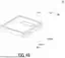
FIG. 1A is a schematic view illustrating a mountable gas exchange device according to an embodiment of the present disclosure;
FIG. 1B is a schematic view illustrating the mountable gas exchange device implemented in an indoor field according to the embodiment of the present disclosure;
FIG. 2 is a schematic cross-sectional view illustrating a filter component of the mountable gas exchange device according to the embodiment of the present disclosure;
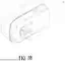
FIG. 3A is a schematic perspective view illustrating a gas detector according to the embodiment of the present disclosure;
FIG. 3B is a schematic perspective view illustrating the gas detector according to the embodiment of the present disclosure and taken from another perspective;
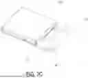
FIG. 3C is a schematic perspective view illustrating the gas detection module installed inside the gas detector according to the embodiment of the present disclosure;
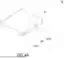
FIG. 4A is a schematic perspective view (1) illustrating a gas detection main part according to the embodiment of the present disclosure;
FIG. 4B is a schematic perspective view (2) illustrating the gas detection main part according to the embodiment of the present disclosure;
FIG. 4C is an exploded view illustrating the gas detection device according to the embodiment of the present disclosure;
FIG. 5A is a schematic perspective view (1) illustrating a base according to the embodiment of the present disclosure;
FIG. 5B is a schematic perspective view (2) illustrating the base according to the embodiment of the present disclosure;
FIG. 6 is a schematic view (3) illustrating the base according to the embodiment of the present disclosure;
FIG. 7A is a schematic exploded view illustrating a combination of a piezoelectric actuator and the base according to the embodiment of the present disclosure;
FIG. 7B is a schematic perspective view illustrating the combination of the piezoelectric actuator and the base according to the embodiment of the present disclosure;
FIG. 8A is a schematic exploded view (1) illustrating the piezoelectric actuator according to the embodiment of the present disclosure;
FIG. 8B is a schematic exploded view (2) illustrating the piezoelectric actuator according to the embodiment of the present disclosure;
FIG. 9A is a schematic cross-sectional view (1) illustrating an action of the piezoelectric actuator according to the embodiment of the present disclosure;
FIG. 9B is a schematic cross-sectional view (2) illustrating an action of the piezoelectric actuator according to the embodiment of the present disclosure;
FIG. 9C is a schematic cross-sectional view (3) illustrating an action of the piezoelectric actuator according to the embodiment of the present disclosure;
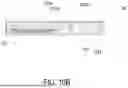
FIG. 10A is a schematic cross-sectional view (1) illustrating the gas detection main part according to the embodiment of the present disclosure;
FIG. 10B is a schematic cross-sectional view (2) illustrating the gas detection main part according to the embodiment of the present disclosure;
FIG. 10C is a schematic cross-sectional view (3) illustrating the gas detection main part according to the embodiment of the present disclosure;
FIG. 11 is a schematic diagram illustrating a communication transmission of the gas detector according to the embodiment of the present invention.
DETAILED DESCRIPTION OF THE PREFERRED EMBODIMENT
The present disclosure will now be described more specifically with reference to the following embodiments. It is to be noted that the following descriptions of preferred embodiments of this invention are presented herein for purpose of illustration and description only. It is not intended to be exhaustive or to be limited to the precise form disclosed.
Please refer to FIG. 1A and FIG. 1B. The present disclosure provides a mountable gas exchange device used in an indoor air cleaning network mechanism. The mountable gas exchange device comprising at least one gas detector 1 and a gas exchange main part 2. The at least one gas detector 1 is arranged in an indoor field A for detecting air pollution information and temperature and humidity information of gas. In the embodiment, the indoor field A comprises at least one gas introducing opening C1 and at least one gas discharging opening C2. The gas exchange main part 2 is built-in and suspended in the indoor field A. The gas exchange main part 2 comprises at least one air guiding fan 21, at least one filter component 22, a driving controller 23 and a flow guiding pathway 24. The flow guiding pathway 24 is fluidly communicated with a gas introducing entrance 24a, a circulating return air port 24b and a filter duct 24c. In the embodiment, the introducing entrance 24a is fluidly communicated with an outdoor field B, the circulating return air port 24b and the filter duct 24c are fluidly communicated with the indoor field A. In some embodiments, a gas exchange fan 25 is arranged at the gas circulation entrance 24b. The at least one air guiding fan 21 and the at least one filter component 22 are arranged under the filter duct 24c. The at least one gas detector 1 is electrically connected to the driving controller 23. Wherein, the at least one gas detector 1 receives a control instruction and transmits it to the driving controller 23 through an Internet of Things communication, so as to control the driving controller 23 to enable an actuation operation of the at least one air guiding fan 21 and the gas exchange fan 25, so that air in the outdoor field B is introduced and filtered through the at least one filter component 22 under the filter duct 24c into the indoor field A. In the mean time, air in the indoor space A enters the filter duct 24c through the circulating return air port 24b to draw air pollution through the at least one filter component 22 for multiple cycles of filtration and temperature adjustment to implement ventilation, so as to achieve complete clean room treatment.
Notably, in the embodiment, the mountable gas exchange device is used for implementing air pollution detection and complete purification in the indoor field A, which is built-in and suspended in the indoor field A without piping, so as to implement ventilation. In this embodiment, when the mountable gas exchange device enable the actuation operation for ventilation, a positive pressure greater than 0 Pa is maintained in the space of the indoor field A to prevent the air pollution of the outdoor field B from entering the indoor field A. Please refer to FIG. 1A, the flow guiding pathway 24 is longitudinally parallel to and separated from the filter duct 24c to reduce the backflow of the filtered gas, so as to achieve complete clean room treatment. In the embodiment, the clean room level of the indoor field A is ZAPClean Room 1˜12. In some embodiments, the air pollution information of the indoor field A and the outdoor field is air pollution data of carbon dioxide (CO2), and ventilation is performed to achieve a zero difference of carbon dioxide (CO2) between the indoor field A and the outdoor field B. In other embodiments, the mountable gas exchange device is a fresh air fan, a full heat exchanger, or a heating, ventilation and air conditioning (HVAC), but not limited to.
Please refer to FIG. 1B. The mountable gas exchange device is used in an indoor air cleaning network mechanism. The indoor air cleaning network mechanism includes a plurality of gas detectors 1, at least one gas molecule control hardware device and a networked cloud computing service device 3. The plurality of detectors 1 are arranged in the indoor field A and the outdoor field B for detecting air pollution information and temperature and humidity information of gas. In the embodiment, the indoor field A comprises at least one gas introducing opening C1 and at least one gas discharging opening C2. The at least one gas molecule control hardware device includes the at least one mountable gas exchange device disposed corresponding to the gas introducing opening C1, at least one purifier 4, at least one fan filter unit 5, at least one exhaust device 6 disposed corresponding to the gas discharging opening C2, at least one extractor hood system 7 disposed corresponding to the gas discharging opening C2, at least one air conditioning device 8, at least one vacuum cleaner 9 and at least one dehumidifier 10 disposed in the indoor field A. In some embodiments, the gas molecule control hardware device includes at least one detector 1, at least one air guiding fan 21, at least one filter component 22 and at least one driving controller 23. The gas detector 1 is electrically connected to the driving controller 23. In the embodiment, the networked cloud computing service device 3 receives the air pollution information and the temperature and humidity information of the indoor field A and the outdoor field B detected by the gas detector 1 through the Internet of Things communication, stores and constructs an air pollution big data database accordingly, and intelligently selects to issue the control instruction to the detector 1, so as to control the driving controller 23 to enable the actuation operation of the air guiding fan 21. Consequently, air in the indoor field A is ventilated, the temperature and the humidity are adjusted, and air pollution is guided through the filter component 22 for multiple cycles of purification and complete clean room treatment, so as to achieve complete clean room treatment, and the gas detector 1 externally transmits the air pollution information and the temperature and humidity information in the indoor field A.
In the embodiment, the at least one gas detector 1 is arranged in an indoor field A and an outdoor field B to detect air pollution information. The at least one gas detector 1 also outputs the air pollution information through Internet of Things (IoT) communication. Notably, in the embodiment, the gas detector 1 includes a gas detection module disposed therein. Please refer to FIG. 3A and FIG. 3B. Preferably but not exclusively, the gas detector 1 is formed by a type of structure including an external power terminal, which can be directly inserted into the power interface in the indoor field A to start the operation of detecting air pollution. In an embodiment, as shown in FIG. 3C, a type of the gas detection module without an external power terminal is directly constructed on a gas molecule control hardware device (e.g., the mountable gas exchange device, the purifier 4, the fan filter unit 5, the exhaust device 6, the extractor hood system 7, the air conditioning device 8, the vacuum cleaner 9 and the dehumidifier 10) and connected to a driving controller 23. A control instruction is received for the driving controller 23 to control the power supply of the gas molecule control hardware device and control actuation operation of the air guiding fan 21.
In the embodiment, Internet of Things communication refers to a collective network, which connects various devices and technologies and helps the devices communicate with the cloud and with each other. Preferably but not exclusively, the IoT communication is a wired communication, which is connected to the networked cloud computing service device 3 via a wired line. Preferably but not exclusively, the IoT communication is a wireless communication for communicating with the networked cloud computing service device 3 via a wireless connection. The wireless communication transmission includes one selected from the group consisting of a Wi-Fi module, a Bluetooth module, a radio frequency identification module, and a near field communication (NFC) module.
Notably, in the embodiment, the air pollution is at least one selected from the group consisting of particulate matter, carbon monoxide, carbon dioxide, ozone, sulfur dioxide, nitrogen dioxide, lead, total volatile organic compounds (TVOC), formaldehyde, bacteria, fungi, virus and a combination thereof.
Certainly, the gas detector 1 monitors the air quality in the space of the indoor field A anytime and anywhere. Moreover, at the same time, the air pollution information in the space of the indoor field A is transmitted to the air pollution big data database of the networked cloud computing service device 3 to intelligently compare the ambient air quality status, and instantly control the air guiding fan 21 arranged in each area to adjust the air volume according to the air quality. The energy-saving benefits of the operation of the gas molecule control hardware device are effectively controlled.
In the present disclosure, the specific implementation of the mountable gas exchange device is understandable, and the structure of the gas detection module of the gas detector 1 of the present disclosure is described in detail below. Please refer to FIG. 3A to FIG. 11. In the embodiment, the gas detection module includes a controlling circuit board 11, a gas detection main part 12, a microprocessor 13 and a communicator 14. The gas detection main part 12, the microprocessor 13 and the communicator 14 are integrally packaged on the controlling circuit board 11 and electrically connected to each other. In the embodiment, the microprocessor 13 and the communicator 14 are mounted on the controlling circuit board 11. The microprocessor 13 controls the driving signal of the gas detection main part 12 for enabling the detection. In this way, the gas detection main part 12 detects the air pollution and outputs the air pollution information, and the microprocessor 13 receives, processes and provides the air pollution information to the communicator 14 for a communication transmission externally, and transmitting to the cloud computing server device 3 through IoT (Internet of Things) communication.
Please refer to FIG. 4A to FIG. 9A. In the embodiment, the gas detection main part 12 includes a base 121, a piezoelectric actuator 122, a driving circuit board 123, a laser component 124, a particulate sensor 125, and an outer cover 126. In the embodiment, the base 121 includes a first surface 1211, a second surface 1212, a laser loading region 1213, a gas-inlet groove 1214, a gas-guiding-component loading region 1215 and a gas-outlet groove 1216. The first surface 1211 and the second surface 1212 are two surfaces opposite to each other. In the embodiment, the laser loading region 1213 is hollowed out from the first surface 1211 toward the second surface 1212. The outer cover 126 covers the base 121 and includes a side plate 1261. The side plate 1261 has an inlet opening 1261a and an outlet opening 1261b. The gas-inlet groove 1214 is concavely formed from the second surface 1212 and disposed adjacent to the laser loading region 1213. The gas-inlet groove 1214 includes a gas-inlet 1214a and two lateral walls. The gas-inlet 1214a is in communication with an environment outside the base 121, and is spatially corresponding in position to an inlet opening 1261a of the outer cover 126. Two transparent windows 1214b are opened on the two lateral walls of the gas-inlet groove 1214 and are in communication with the laser loading region 1213. Therefore, the first surface 1211 of the base 121 is covered and attached by the outer cover 126, and the second surface 1212 is covered and attached by the driving circuit board 123, so that an inlet path is defined by the gas-inlet groove 1214. In the embodiment, the gas-guiding-component loading region 1215 mentioned above is concavely formed from the second surface 1212 and in communication with the gas-inlet groove 1214. A ventilation hole 1215a penetrates a bottom surface of the gas-guiding-component loading region 1215. The gas-guiding-component loading region 1215 includes four positioning protrusions 1215b disposed at four corners of the gas-guiding-component loading region 1215, respectively. In the embodiment, the gas-outlet groove 1216 includes a gas-outlet 1216a, and the gas-outlet 1216a is spatially corresponding to the outlet opening 1261b of the outer cover 126. The gas-outlet groove 1216 includes a first section 1216b and a second section 1216c. The first section 1216b is concavely formed out from the first surface 1211 in a region spatially corresponding to a vertical projection area of the gas-guiding-component loading region 1215. The second section 1216c is hollowed out from the first surface 1211 to the second surface 1212 in a region where the first surface 1211 is extended from the vertical projection area of the gas-guiding-component loading region 1215. The first section 1216b and the second section 1216c are connected to form a stepped structure. Moreover, the first section 1216b of the gas-outlet groove 1216 is in communication with the ventilation hole 1215a of the gas-guiding-component loading region 1215, and the second section 1216c of the gas-outlet groove 1216 is in communication with the gas-outlet 1216a. In that, when first surface 1211 of the base 121 is attached and covered by the outer cover 126 and the second surface 1212 of the base 121 is attached and covered by the driving circuit board 123, the gas-outlet groove 1216 and the driving circuit board 123 collaboratively define an outlet path.
In the embodiment, the laser component 124 and the particulate sensor 125 are disposed on and electrically connected to the driving circuit board 123 and located within the base 121. In order to clearly describe and illustrate the positions of the laser component 124 and the particulate sensor 125 in the base 121, the driving circuit board 123 is intentionally omitted. The laser component 124 is accommodated in the laser loading region 1213 of the base 121, and the particulate sensor 125 is accommodated in the gas-inlet groove 1214 of the base 121 and is aligned to the laser component 124. In addition, the laser component 124 is spatially corresponding to the transparent window 1214b, therefore, a light beam emitted by the laser component 124 passes through the transparent window 1214b and is irradiated into the gas-inlet groove 1214. A light beam path emitted from the laser component 124 passes through the transparent window 1214b and extends in an orthogonal direction perpendicular to the gas-inlet groove 1214. In the embodiment, a projecting light beam emitted from the laser component 124 passes through the transparent window 1214b and enters the gas-inlet groove 1214 to irradiate the suspended particles contained in the gas passing through the gas-inlet groove 1214. When the suspended particles contained in the gas are irradiated and generate scattered light spots, the scattered light spots are received and calculated by the particulate sensor 125 to obtain the gas detection information.
In the embodiment, the piezoelectric actuator 122 is accommodated in the square-shaped gas-guiding-component loading region 1215 of the base 121. In addition, the gas-guiding-component loading region 1215 of the base 121 is in fluid communication with the gas-inlet groove 1214. When the piezoelectric actuator 122 is enabled, the gas in the gas-inlet groove 1214 is inhaled by the piezoelectric actuator 122, so that the gas flows into the piezoelectric actuator 122, and is transported into the gas-outlet groove 1216 through the ventilation hole 1215a of the gas-guiding-component loading region 1215. Moreover, the driving circuit board 123 covers the second surface 1212 of the base 121, and the laser component 124 is disposed on the driving circuit board 123, and is electrically connected to the driving circuit board 123. The particulate sensor 125 is also disposed on the driving circuit board 123 and electrically connected to the driving circuit board 123. In that, when the outer cover 126 covers the base 121, the inlet opening 1261a is spatially corresponding to the gas-inlet 1214a of the base 121, and the outlet opening 1261b is spatially corresponding to the gas-outlet 1216a of the base 121.
In the embodiment, the piezoelectric actuator 122 includes a gas-injection plate 1221, a chamber frame 1222, an actuator element 1223, an insulation frame 1224 and a conductive frame 1225. In the embodiment, the gas-injection plate 1221 is made by a flexible material and includes a suspension plate 1221a and a hollow aperture 1221b. The suspension plate 1221a is a sheet structure and is permitted to undergo a bending deformation. Preferably but not exclusively, the shape and the size of the suspension plate 1221a are accommodated in the inner edge of the gas-guiding-component loading region 1215, but not limited thereto. The hollow aperture 1221b passes through a center of the suspension plate 1221a, so as to allow the gas to flow therethrough. Preferably but not exclusively, in the embodiment, the shape of the suspension plate 1221a is selected from the group consisting of a square, a circle, an ellipse, a triangle and a polygon, but not limited thereto.
In the embodiment, the chamber frame 1222 is carried and stacked on the gas-injection plate 1221. In addition, the shape of the chamber frame 1222 is corresponding to the gas-injection plate 1221. The actuator element 1223 is carried and stacked on the chamber frame 1222. A resonance chamber 1226 is collaboratively defined by the actuator element 1223, the chamber frame 1222 and the suspension plate 1221a and is formed between the actuator element 1223, the chamber frame 1222 and the suspension plate 1221a. The insulation frame 1224 is carried and stacked on the actuator element 1223 and the appearance of the insulation frame 1224 is similar to that of the chamber frame 1222. The conductive frame 1225 is carried and stacked on the insulation frame 1224, and the appearance of the conductive frame 1225 is similar to that of the insulation frame 1224. In addition, the conductive frame 1225 includes a conducting pin 1225a and a conducting electrode 1225b. The conducting pin 1225a is extended outwardly from an outer edge of the conductive frame 1225, and the conducting electrode 1225b is extended inwardly from an inner edge of the conductive frame 1225. Moreover, the actuator element 1223 further includes a piezoelectric carrying plate 1223a, an adjusting resonance plate 1223b and a piezoelectric plate 1223c. The piezoelectric carrying plate 1223a is carried and stacked on the chamber frame 1222. The adjusting resonance plate 1223b is carried and stacked on the piezoelectric carrying plate 1223a. The piezoelectric plate 1223c is carried and stacked on the adjusting resonance plate 1223b. The adjusting resonance plate 1223b and the piezoelectric plate 1223c are accommodated in the insulation frame 1224. The conducting electrode 1225b of the conductive frame 1225 is electrically connected to the piezoelectric plate 1223c. In the embodiment, the piezoelectric carrying plate 1223a and the adjusting resonance plate 1223b are made by a conductive material. The piezoelectric carrying plate 1223a includes a piezoelectric pin 1223d. The piezoelectric pin 1223d and the conducting pin 1225a are electrically connected to a driving circuit (not shown) of the driving circuit board 123, so as to receive a driving signal, such as a driving frequency and a driving voltage. Through this structure, a circuit is formed by the piezoelectric pin 1223d, the piezoelectric carrying plate 1223a, the adjusting resonance plate 1223b, the piezoelectric plate 1223c, the conducting electrode 1225b, the conductive frame 1225 and the conducting pin 1225a for transmitting the driving signal. Moreover, the insulation frame 1224 is insulated between the conductive frame 1225 and the actuator element 1223, so as to avoid the occurrence of a short circuit. Thereby, the driving signal is transmitted to the piezoelectric plate 1223c. After receiving the driving signal such as the driving frequency and the driving voltage, the piezoelectric plate 1223c deforms due to the piezoelectric effect, and the piezoelectric carrying plate 1223a and the adjusting resonance plate 1223b are further driven to generate the bending deformation in the reciprocating manner.
Furthermore, in the embodiment, the adjusting resonance plate 1223b is located between the piezoelectric plate 1223c and the piezoelectric carrying plate 1223a and served as a cushion between the piezoelectric plate 1223c and the piezoelectric carrying plate 1223a. Thereby, the vibration frequency of the piezoelectric carrying plate 1223a is adjustable. Basically, the thickness of the adjusting resonance plate 1223b is greater than the thickness of the piezoelectric carrying plate 1223a, and the vibration frequency of the actuator element 1223 can be adjusted by adjusting the thickness of the adjusting resonance plate 1223b.
Please further refer to FIG. 7A, FIG. 7B, FIG. 8A, FIG. 8B and FIG. 9A. In the embodiment, the gas-injection plate 1221, the chamber frame 1222, the actuator element 1223, the insulation frame 1224 and the conductive frame 1225 are stacked and positioned in the gas-guiding-component loading region 1215 sequentially, so that the piezoelectric actuator 122 is supported and positioned in the gas-guiding-component loading region 1215. A plurality of clearances 1221c are defined between the suspension plate 1221a of the gas-injection plate 1221 and an inner edge of the gas-guiding-component loading region 1215 for gas flowing therethrough. In the embodiment, a flowing chamber 1227 is formed between the gas-injection plate 1221 and the bottom surface of the gas-guiding-component loading region 1215. The flowing chamber 1227 is in communication with the resonance chamber 1226 between the actuator element 1223, the chamber frame 1222 and the suspension plate 1221a through the hollow aperture 1221b of the gas-injection plate 1221. By controlling the vibration frequency of the gas in the resonance chamber 1226 to be close to the vibration frequency of the suspension plate 1221a, the Helmholtz resonance effect is generated between the resonance chamber 1226 and the suspension plate 1221a, so as to improve the efficiency of gas transportation. When the piezoelectric plate 1223c is moved away from the bottom surface of the gas-guiding-component loading region 1215, the suspension plate 1221a of the gas-injection plate 1221 is driven to move away from the bottom surface of the gas-guiding-component loading region 1215 by the piezoelectric plate 1223c. In that, the volume of the flowing chamber 1227 is expanded rapidly, the internal pressure of the flowing chamber 1227 is decreased to form a negative pressure, and the gas outside the piezoelectric actuator 122 is inhaled through the clearances 1221c and enters the resonance chamber 1226 through the hollow aperture 1221b. Consequently, the pressure in the resonance chamber 1226 is increased to generate a pressure gradient. When the suspension plate 1221a of the gas-injection plate 1221 is driven by the piezoelectric plate 1223c to move toward the bottom surface of the gas-guiding-component loading region 1215, the gas in the resonance chamber 1226 is discharged out rapidly through the hollow aperture 1221b, and the gas in the flowing chamber 1227 is compressed, thereby the converged gas is quickly and massively ejected out of the flowing chamber 1227 under the condition close to an ideal gas state of the Benulli's law, and transported to the ventilation hole 1215a of the gas-guiding-component loading region 1215.
By repeating the above operation steps shown in FIG. 9B and FIG. 9C, the piezoelectric plate 1223c is driven to generate the bending deformation in a reciprocating manner. According to the principle of inertia, since the gas pressure inside the resonance chamber 1226 is lower than the equilibrium gas pressure after the converged gas is ejected out, the gas is introduced into the resonance chamber 1226 again. Moreover, the vibration frequency of the gas in the resonance chamber 1226 is controlled to be close to the vibration frequency of the piezoelectric plate 1223c, so as to generate the Helmholtz resonance effect to achieve the gas transportation at high speed and in large quantities. The gas is inhaled through the gas-inlet 1214a on the outer cover 126, flows into the gas-inlet groove 1214 of the base 121 through the gas-inlet 1214a, and is transported to the position of the particulate sensor 125. The piezoelectric actuator 122 is enabled continuously to inhale the gas into the inlet path, and facilitate the gas outside the gas detection module to be introduced rapidly, flow stably, and transported above the particulate sensor 125. At this time, a projecting light beam emitted from the laser component 124 passes through the transparent window 1214b to irritate the suspended particles contained in the gas flowing above the particulate sensor 125 in the gas-inlet groove 1214. When the suspended particles contained in the gas are irradiated and generate scattered light spots, the scattered light spots are received and calculated by the particulate sensor 125 for obtaining related information about the sizes and the concentration of the suspended particles contained in the gas. Moreover, the gas above the particulate sensor 125 is continuously driven and transported by the piezoelectric actuator 122, flows into the ventilation hole 1215a of the gas-guiding-component loading region 1215, and is transported to the gas-outlet groove 1216. At last, after the gas flows into the gas outlet groove 1216, the gas is continuously transported into the gas-outlet groove 1216 by the piezoelectric actuator 122, and thus the gas in the gas-outlet groove 1216 is pushed to discharge through the gas-outlet 1216a and the outlet opening 1261b.
The gas detector 1 of the present disclosure not only can detect the particulate matters in the gas, but also can detect the gas characteristics of the introduced gas, for example, to determine whether the gas is formaldehyde, ammonia, carbon monoxide, carbon dioxide, oxygen, ozone, or the like. Therefore, in one or some embodiments, the gas detector 1 of the present disclosure further includes a gas sensor 127 positioned and disposed on the driving circuit board 123, electrically connected to the driving circuit board 123, and accommodated in the gas-outlet groove 1216, so as to detect the air pollution introduced into the gas-outlet groove 1216. Preferably but not exclusively, in an embodiment, the gas sensor 127 includes a volatile-organic-compound sensor for detecting the information of carbon dioxide (CO2) or volatile organic compounds (TVOC). Preferably but not exclusively, in an embodiment, the gas sensor 127 includes a formaldehyde sensor for detecting the information of formaldehyde (HCHO) gas. Preferably but not exclusively, in an embodiment, the gas sensor 127 includes a bacteria sensor for detecting the information of bacteria or fungi. Preferably but not exclusively, in an embodiment, the gas sensor 127 includes a virus sensor for detecting the information of virus in the gas. Preferably but not exclusively, the gas sensor 127 is a temperature and humidity sensor for detecting the temperature and humidity information of the gas.
Please refer to FIG. 2. In the embodiment, the air guiding fan 21 of the mountable gas exchange device is controlled to start and guide the air pollution to pass through the filter component 22 for filtration. Preferably but not exclusively, the filter component 22 is a filter with a grade of minimum filtration efficiency value (MREV) 8 or above, or a filter with high-efficiency particulate air (HEPA) grade, which is configured to absorb the chemical smoke, the bacteria, the dust particles and the pollen contained in the air pollution, so that the air pollution introduced into the filter component 22 is filtered and purified to achieve the effect of filtering and purification. Notably, in the present disclosure, the filter with the high efficiency particulate air (HEPA) grade is of 10 or above, and has a dust holding capacity greater than 12,000 mg. In an embodiment, the filter component 22 of the present disclosure is further combined with physical or chemical materials to provide a sterilization effect on the air pollution, and the airflow of the air guiding fan 21 flows in the path indicated by the arrow. In an embodiment, the filter component 22 includes a decomposition layer coated thereon to sterilize in chemical means. Preferably but not exclusively, the decomposition layer includes an activated carbon 22a configured to remove organic and inorganic substances in air pollution, and remove colored and odorous substances. Preferably but not exclusively, the activated carbon has a formaldehyde absorption capacity greater than 1,500 mg. In an embodiment, the decomposition layer includes a cleansing factor containing chlorine dioxide layer 22b configured to inhibit viruses, bacteria, fungi, influenza A, influenza B, enterovirus and norovirus in the air pollution, and the inhibition ratio can reach 99% and more, thereby reducing the cross-infection of viruses. In an embodiment, the decomposition layer includes an herbal protective layer 22c extracted from ginkgo and Japanese Rhus chinensis configured to resist allergy effectively and destroy a surface protein of influenza virus (such as H1N1 influenza virus) passing therethrough. In an embodiment, the decomposition layer includes a silver ion 22d configured to inhibit viruses, bacteria and fungi contained in the air pollution. In an embodiment, the decomposition layer includes a zeolite 22e configured to remove ammonia nitrogen, heavy metals, organic pollutants, Escherichia coli, phenol, chloroform and anionic surfactants. Furthermore, in some embodiments, the filter component 22 is combined with a light irradiation element to sterilize in chemical means. Preferably but not exclusively, the light irradiation element is a photo-catalyst unit including a photo catalyst 22f and an ultraviolet lamp 22g. When the photo catalyst 22f is irradiated by the ultraviolet lamp 22g, the light energy is converted into the chemical energy, thereby decomposes harmful gases and disinfects bacteria contained in the air pollution, so as to achieve the effects of filtering and purifying. Notably, the power of the ultraviolet lamp 22g in the present disclosure is more than 120 mw. In an embodiment, the light irradiation element is a photo-plasma unit including a nanometer irradiation tube 22h. When the introduced air pollution is irradiated by the nanometer irradiation tube 22h, the oxygen molecules and water molecules contained in the air pollution are decomposed into high oxidizing photo-plasma, and an ion flow capable of destroying organic molecules is generated. In that, volatile formaldehyde, volatile toluene and volatile organic compounds (VOC) contained in the air pollution are decomposed into water and carbon dioxide, so as to achieve the effects of filtering and purifying. Moreover, in some embodiments, the filter component 22 is combined with a decomposition unit to sterilize in chemical means. Preferably but not exclusively, the decomposition unit is a negative ion unit 22i with a dust collecting plate. It makes the suspended particles in the air pollution to carry with positive charge and adhered to the dust collecting plate carry with negative charges, so as to achieve the effects of filtering and purifying. Preferably but not exclusively, the decomposition unit is a plasma ion unit 22j. The oxygen molecules and water molecules contained in the air pollution are decomposed into positive hydrogen ions (H+) and negative oxygen ions (O2−) by the plasma ion. The substances attached with water around the ions are adhered on the surface of viruses and bacteria and converted into OH radicals with extremely strong oxidizing power, thereby removing hydrogen (H) from the protein on the surface of viruses and bacteria, and thus decomposing (oxidizing) the protein, so as to filter the introduced air pollution and achieve the effects of filtering and purifying.
In summary, the present disclosure provides a mountable gas exchange device for implementing air pollution detection and complete purification in the space of an indoor field. The mountable gas exchange device is equipped with at least one gas detector, at least one air guiding fan, at least one filter component, a driving controller and a flow guiding pathway which is design without piping. The gas detector is electrically connected to the driving controller and connected to a networked cloud computing service device of the indoor air cleaning network mechanism to form an intelligent linkage system. At this time, the gas detector receives a control instruction from the networked cloud computing service device of the indoor air cleaning network mechanism through an Internet of Things communication, and controls actuation operation of the air guiding fan and the gas exchange fan, so that air in the outdoor field is introduced and air pollution is drew to the filter component for multiple cycles of filtration and temperature adjustment to implement ventilation. When the mountable gas exchange device enable the actuation operation for ventilation, a positive pressure greater than 0 Pa is maintained in the space of the indoor field to prevent the air pollution of the outdoor field from mechanism is established in this way to obtain the room temperature in the indoor field, achieve zero difference of carbon dioxide (CO2) in the indoor field and the outdoor field, and perform the clean room treatment to purify the PM2.5 and other air pollution in the indoor field completely. At the same time, the air pollution in the space of the indoor field is detected by intelligently comparing the ambient air quality status, and the air guiding fan is instantly controlled to adjust the air flow volume according to the air quality, thereby effectively adjusting the energy-saving efficiency of the operation of the mountable gas exchange device. Consequently, the air flow volume noise reaches zero specification value, thereby achieving the ultimate environmental protection of balanced energy saving and power saving. The present disclosure includes the industrial applicability and the inventive steps.
Claims
What is claimed is:1. A mountable gas exchange device used in an indoor air cleaning network mechanism, the mountable gas exchange device comprising:
at least one gas detector arranged in an indoor field for detecting air pollution information and temperature and humidity information of gas, wherein the indoor field comprises at least one gas introducing opening and at least one gas discharging opening; and
a gas exchange main part built-in and suspended in the indoor field, and comprising at least one air guiding fan, at least one filter component, a driving controller and a flow guiding pathway, wherein the flow guiding pathway is fluidly communicated with a gas introducing entrance, a circulating return air port and a filter duct, the introducing entrance is fluidly communicated with an outdoor field, the circulating return air port and filter duct are fluidly communicated with the indoor field, and a gas exchange fan is arranged at the gas circulation entrance, wherein the at least one air guiding fan and the at least one filter component are arranged under the filter duct, and the at least one gas detector is electrically connected to the driving controller;
wherein the at least one gas detector receives a control instruction and transmits it to the driving controller through an Internet of Things communication, so as to control the driving controller to enable an actuation operation of the at least one air guiding fan and the gas exchange fan, so that air in the outdoor field is introduced and filtered through the at least one filter component under the filter duct into the indoor field, and air in the indoor space enters the filter duct through the circulating return air port to draw air pollution through the at least on filter component for multiple cycles of filtration and temperature adjustment to implement ventilation, so as to achieve complete clean room treatment.
2. The mountable gas exchange device according to claim 1, wherein the air pollution information of the indoor field and the outdoor field is air pollution data of carbon dioxide (CO2), and ventilation is performed to achieve a zero difference of carbon dioxide (CO2) between the indoor field and the outdoor field.
3. The mountable gas exchange device according to claim 1, wherein when the mountable gas exchange device enable the actuation operation for ventilation, a positive pressure greater than 0 Pa is maintained in the space of the indoor field to prevent air pollution in the outdoor field from entering the indoor field.
4. The mountable gas exchange device according to claim 1, wherein the mountable gas exchange device is a fresh air fan, a full heat exchanger, or a heating, ventilation and air conditioning (HVAC).
5. The mountable gas exchange device according to claim 1, wherein the at least one gas detector transmits the air pollution information and the temperature and humidity information to a networked cloud computing service device of the indoor air cleaning network mechanism through the Internet of Things communication, wherein the networked cloud computing service device receives the air pollution information and the temperature and humidity information of the indoor field and the outdoor field, stores and constructs an air pollution big data database accordingly, intelligently computes and compares according to the air pollution big data database, and intelligently selects to issue the control instruction to the at least one gas detector, so as to control the driving controller to enable the actuation operation of the at least one air guiding fan and the gas exchange fan.
6. The mountable gas exchange device according to claim 1, wherein the at least one filter component is a filter with a minimum efficiency reporting value (MREV) of 8 or above.
7. The mountable gas exchange device according to claim 1, wherein the at least one filter component is a filter with a high efficiency particulate air (HEPA) grade, and the high efficiency particulate air (HEPA) grade is of 10 or above, and has a dust holding capacity greater than 12,000 mg.
8. The mountable gas exchange device according to claim 1, wherein the at least one filter component is combined with a decomposition layer coated thereon, and the decomposition layer uses chemical means to sterilize the air pollution.
9. The mountable gas exchange device according to claim 8, wherein the decomposition layer is composed of an activated carbon or a cleansing factor containing chlorine dioxide layer, wherein the activated carbon has a formaldehyde absorption capacity greater than 1,500 mg.
10. The mountable gas exchange device according to claim 8, wherein the decomposition layer comprises at least one selected from the group consisting of an herbal protective layer extracted from ginkgo and Japanese Rhus chinensis, a silver ion, a zeolite and a combination thereof.
11. The mountable gas exchange device according to claim 1, wherein the at least one filter component is combined with a light irradiation element to sterilize in chemical means, and the light irradiation element is a photo-catalyst unit including a photo catalyst and an ultraviolet lamp, wherein the power of the ultraviolet lamp is more than 120 mw.
12. The mountable gas exchange device according to claim 11, wherein the light irradiation element is a photo-plasma unit including a nanometer irradiation tube.
13. The mountable gas exchange device according to claim 1, wherein the at least one filter component is combined with a decomposition unit to sterilize in chemical means, the decomposition unit is a negative ion unit or a plasma ion unit.
14. The mountable gas exchange device according to claim 1, wherein the clean room level of the indoor field is ZAPClean Room 1˜12.
Images & Drawings included:


Sources:
- United States Patent and Trademark Office - verify current appl. status at the USPTO↗
Recent applications in this class:
- » 20250264229 2025-08-21
AIR CLEANER - » 20240230111 2024-07-11
INDOOR UNIT AND AIR CONDITIONER - » 20220373197 2022-11-24
AIR-CONDITIONING SYSTEM - » 20210325053 2021-10-21
Air handling apparatus - » 20210172621 2021-06-10
Air management apparatus or device - » 20210172620 2021-06-10
Air management apparatus or device - » 20210140652 2021-05-13
Filter assembly for an air conditioner unit - » 20200149750 2020-05-14
Air treatment device and air conditioner indoor unit having the same - » 20120164931 2012-06-28
Operational noise control method for air conditioner - » 20110120066 2011-05-26
Cleaning unit of air conditioner
Recent applications for this Assignee:
- » 20260022851 2026-01-22
MOUNTABLE FAN FILTER ASSEMBLY - » 20260022850 2026-01-22
INDOOR AIR CLEANING NETWORK MECHANISM SYSTEM - » 20260009553 2026-01-08
INDOOR AIR CLEANING SYSTEM WITH NETWORKING MECHANISM - » 20250389434 2025-12-25
EXPANDABLE CLEANING DEVICE - » 20250383097 2025-12-18
RANGE HOOD - » 20250327593 2025-10-23
METHOD OF REALIZING BENEFITS OF INDOOR CLEANING SYSTEM THROUGH ARTIFICIAL INTELLIGENCE GENERATED CONTENT - » 20250319698 2025-10-16
INKJET CHIP STRUCTURE - » 20250290653 2025-09-18
GENERATIVE ARTIFICIAL INTELLIGENCE INDOOR AIR CLEANING SYSTEM - » 20250271158 2025-08-28
INDOOR AIR CLEANING SYSTEM - » 20250264243 2025-08-21
INDOOR AIR CLEANING SYSTEM