System and Method for Measuring Torque
US20260022983A1
2026-01-22
19/274,802
2025-07-21
Smart Summary: A new system measures torque in hydraulic tongs used for heavy lifting. It has a pressure sensor that checks the pressure in the hydraulic line. This sensor sends the pressure information to a controller. The controller then changes this data into torque measurements and shares it with a user device. If the torque gets too high, the controller tells a valve to open and release pressure. 🚀 TL;DR
Abstract:
A system for measuring torque in hydraulically powered tongs. The system including a pressure transducer, a dump valve, and a controller. The pressure transducer measures the pressure in the hydraulic line of the tongs and sends the data to the controller. The controller converts the data to torque measurements and reports it to a user device. If the torque measurements exceed a certain amount, the controller signals the dump valve to open.
Inventors:
- Maximo Tejeda 9 🇺🇸 Houston, TX, United States
- Maximo Tejeda, JR. 7 🇺🇸 Houston, TX, United States
- Rick Nichols 1 🇺🇸 Houston, TX, United States
Applicant:
Interested in similar patents?
Get notified when new applications in this technology area are published.
Classification:
G01L5/24 » CPC main
Apparatus for, or methods of, measuring force, work, mechanical power, or torque, specially adapted for specific purposes for determining value of torque or twisting moment for tightening a nut or other member which is similarly stressed
Description
CROSS REFERENCE TO RELATED APPLICATION
This application claims priority to U.S. Application No. 63/673,867 filed on Jul. 22, 2024, the disclosure of which is incorporated herein by reference for all purposes.
FIELD OF THE INVENTION
The present invention relates to a system for measuring torque. In particular, the present invention relates to a system for measuring make-up/break-out torque of threaded pipe connections in the oil and gas industry.
BACKGROUND OF THE INVENTION
In the oil and gas industry, hydraulically powered wrenches known as tongs are used to make up and break casing and tubing connections. When making up connections, it is important to know the amount of torque being applied to ensure a proper connection. Typically, when torque reporting is required, a subcontractor brings in specially designed tongs having torque and turn sensors, tension load cells or pancake load cells, and which are operated by proprietary software systems. This specialized service greatly increases the cost of the overall operation.
SUMMARY OF THE INVENTION
In one aspect, the present invention relates to a system for measuring the torque of hydraulic tongs.
In another aspect, the present invention relates to a system for measuring the torque of hydraulic tongs which can be retrofit to existing oilfield systems.
BRIEF DESCRIPTION OF THE DRAWINGS
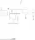
FIG. 1 depicts one embodiment of the system of the present invention.
FIG. 2 shows one example of the torque measurements displayed by the system of the present invention.
FIG. 3 shows another example of the torque measurements displayed by the system of the present invention.
DETAILED DESCRIPTION OF PREFERRED EMBODIMENTS
Embodiments of the invention are described more fully hereafter with reference to the accompanying drawings. Elements that are identified using the same or similar reference characters refer to the same or similar elements which perform the same functions across various embodiments. The various embodiments of the invention may, however, be embodied in many different forms and should not be construed as limited to the embodiments set forth herein. Rather, these embodiments are provided so that this disclosure will be thorough and complete, and will fully convey the scope of the invention to those skilled in the art.
FIG. 1 depicts one embodiment of the system 10 of the present invention. The system 10 includes a pressure transducer 12 connected to the hydraulic line H of oilfield tongs T. In a preferred embodiment, the pressure transducer 12 is digital with a visual display. Pressure transducer 12 is operatively connected, through a wired or wireless connection, to a controller 20 (e.g., a programmable logic controller). Pressure transducer 12 transmits real time measurements of the fluid pressure in the hydraulic system of tongs to the controller 20. Controller 20 converts the pressure measurements to a measurement of torque produced by tongs and saves the information. In a preferred embodiment, controller 20 is connected, by wired or wireless connection, to a user device 30. User device 30 may comprise a PC, laptop, mobile phone, tablet, flash drive, printer, or any other device operated by users to manage data.
In addition to measuring the torque of the tongs, the system 10 of the present invention preferably includes a dump valve 14 operatively connected to the tongs and the controller 20. If the measured torque exceeds a certain amount, the controller 20 opens the dump valve. The hydraulic fluid is then drained from the tongs and the make-up operation stopped.
The system can provide real time data of the torque generated by the tongs. The system of the present invention preferably generates periodic reports of the torque data, the frequency and contents of which can be determined by the needs of the user. FIGS. 2 and 3 show examples of the torque generated by the tongs. As shown in FIG. 2, the torque rises and falls over time. As can be seen in FIG. 3, the torque exceeded the maximum amount allowed, triggering the dump valve. The torque then immediately dropped back down to zero as the fluid was drained away to a storage tank S, recycle tank, or the like.
In use, the system 10 of the present invention is installed on existing tongs. The make-up torque parameters for the particular casing/pipe/coupling of the particular operation are entered into the controller so that the maximum permitted torque can be determined.
The system 10 of the present invention provides several advantages over the prior art. The system 10 can be retrofit onto any prior tong system and is more cost effective than the prior art torque-turn tongs. The system 10 does not require any load cells of any kind. The automated dump valve improves safety by ceasing the torque operations without endangering personnel, and reduces costs by avoiding damage caused by over-torquing connections. The constant monitoring of the system allows for an improved maintenance schedule. Consistently lower-than-expected pressure measurements can indicate a leak in the hydraulics system. Such leak can be repaired before causing major damage to the system.
It will be appreciated that typical components, conduits, cables, and the like required to operate the system may not be depicted herein but are well known to those skilled in the art.
Although specific embodiments of the invention have been described herein in some detail, this has been done solely for the purposes of explaining the various aspects of the invention and is not intended to limit the scope of the invention as defined in the claims which follow. Those skilled in the art will understand that the embodiment shown and described is exemplary, and various other substitutions, alterations and modifications, including but not limited to those design alternatives specifically discussed herein, may be made in the practice of the invention without departing from its scope.
Claims
What is claimed is:1. A system for measuring the torque of tongs powered by a hydraulic system, comprising:
a pressure transducer operatively connected to the hydraulic system of the tongs to measure pressure therein;
a dump valve operatively connected to the hydraulic system of the tongs;
a controller operatively connected to the pressure transducer and the dump valve;
the controller programmed to receive pressure measurements from the pressure transducer and to convert the pressure measurements into torque measurements.
2. The system of claim 1, wherein if the torque measurements exceed a certain amount, the controller signals the dump valve to open.
3. The system of claim 1, wherein the controller sends the torque measurements to a user device.
Images & Drawings included:


Sources:
- United States Patent and Trademark Office - verify current appl. status at the USPTO↗
Similar patent applications:
- » 20120072130
Method of measuring torque and torque measuring system for said method - » 20150330851
Adaptive wireless torque measurement system and method - » 20090095089
Index torque measurement system and method - » 20190161139
TORQUE SENSOR SYSTEM, TORQUE SIGNAL MEASURING METHOD, ELECTRIC POWER-ASSISTED BICYCLE - » 20170052076
Sensor device, driving system, method for measuring a torque and method for controlling a driving system - » 20190003908
Sensor device, driving system, method for measuring a torque and method for controlling a driving system - » 20220112695
Work machines incorporating encoder systems, drive assemblies therefor, and methods of measuring torque using encoder systems - » 20170003182
Systems and methods for measuring torque on rotating shaft - » 20050044968
Method and system for measuring torque - » 20140283621
Torque measuring system and a method thereof
Recent applications in this class:
- » 20260016354 2026-01-15
BOLT AXIAL FORCE MONITORING APPARATUS AND MONITORING METHOD - » 20250314546 2025-10-09
DETERMINING RESIDUAL TENSION IN THREADED FASTENERS - » 20250283769 2025-09-11
TORQUE MEASUREMENT WITH COMPENSATION FOR STRAIN GAUGE BIAS - » 20250027826 2025-01-23
CONNECTION PORT FOR A TEST AND/OR MEASUREMENT DEVICE - » 20240418591 2024-12-19
DETERMINING TIGHTENING CLASS OF A TIGHTENING OPERATION PERFORMED BY A TIGHTENING TOOL - » 20240402026 2024-12-05
METHOD OF DESIGNING A BOLTED JOINT - » 20240369432 2024-11-07
DETERMINING CORRECTNESS OF ESTIMATED TIGHTENING CLASSES - » 20240369431 2024-11-07
ML ESTIMATION OF TIGHTENING CLASSES - » 20240142327 2024-05-02
TENSION MONITORING APPARATUS - » 20240035909 2024-02-01
METHOD TO CHECK THE CORRECT FUNCTIONING OF A TIGHTENING TOOL