BACKHOE TILTING ATTACHMENT
US20260028792A1
2026-01-29
19/282,516
2025-07-28
Smart Summary: A backhoe tilting attachment helps control the angle of the bucket attached to a backhoe. It has a fixed back part that connects to the backhoe and a front part that can rotate. A special pivot joint allows the front part to tilt while a piston moves it side to side. This design makes it easier to adjust the bucket's angle accurately. It improves the backhoe's ability to shape trenches or grade surfaces in different conditions. 🚀 TL;DR
Abstract:
Apparatus and associated methods relate to a modular backhoe tilting attachment that allows controlled lateral tilting of a bucket relative to the backhoe's frame through an integrated pivot mechanism. In an illustrative example, the attachment includes a stationary rear portion that couples to a backhoe linkage using oppositely disposed hooks and apertures, and a rotatable front portion that interfaces with a bucket at multiple points. A coaxial pivot joint allows relative rotation between these portions, actuated by a laterally offset piston connected transversely across the joint. Various embodiments may advantageously provide precise bucket angle adjustment and enable enhanced control in trench shaping or grading operations under variable site conditions.
Assignee:
- Ty Traylor 1 🇺🇸 Pima, AZ, United States
Applicant:
Interested in similar patents?
Get notified when new applications in this technology area are published.
Classification:
E02F3/32 » CPC main
Dredgers; Soil-shifting machines mechanically-driven with digging tools mounted on a dipper- or bucket-arm, i.e. there is either one arm or a pair of arms , e.g. dippers, buckets with a dipper-arm pivoted on a cantilever beam, i.e. boom working downwardly and towards the machine, e.g. with backhoes
E02F3/3654 » CPC further
Dredgers; Soil-shifting machines mechanically-driven with digging tools mounted on a dipper- or bucket-arm, i.e. there is either one arm or a pair of arms , e.g. dippers, buckets; Component parts; Devices to connect tools to arms, booms or the like of the quick acting type, e.g. controlled from the operator seat with energy coupler, e.g. coupler for hydraulic or electric lines, to provide energy to drive(s) mounted on the tool
E02F3/3681 » CPC further
Dredgers; Soil-shifting machines mechanically-driven with digging tools mounted on a dipper- or bucket-arm, i.e. there is either one arm or a pair of arms , e.g. dippers, buckets; Component parts; Devices to connect tools to arms, booms or the like allowing movement, e.g. rotation or translation, of the tool around or along another axis as the movement implied by the boom or arms, e.g. for tilting buckets Rotators
E02F3/844 » CPC further
Dredgers; Soil-shifting machines mechanically-driven; Graders, bulldozers, or the like with scraper plates or ploughshare-like elements ; Levelling devices; Component parts; Drives or control devices therefor, e.g. hydraulic drive systems for positioning the blade, e.g. hydraulically
E02F9/2267 » CPC further
Component parts of dredgers or soil-shifting machines, not restricted to one of the kinds covered by groups - ; Drives; Control devices; Hydraulic or pneumatic drives; Arrangements or adaptations of elements for hydraulic drives Valves or distributors
E02F3/36 IPC
Dredgers; Soil-shifting machines mechanically-driven with digging tools mounted on a dipper- or bucket-arm, i.e. there is either one arm or a pair of arms , e.g. dippers, buckets Component parts
E02F3/84 IPC
Dredgers; Soil-shifting machines mechanically-driven; Graders, bulldozers, or the like with scraper plates or ploughshare-like elements ; Levelling devices; Component parts Drives or control devices therefor, e.g. hydraulic drive systems
E02F9/22 IPC
Component parts of dredgers or soil-shifting machines, not restricted to one of the kinds covered by groups - ; Drives; Control devices Hydraulic or pneumatic drives
Description
CROSS-REFERENCE TO RELATED APPLICATIONS
This application is a continuation-in-part and claims the benefit of U.S. Application Ser. No. 63/676,185, titled “BACKHOE TILTING ATTACHMENT,” filed by Ty Traylor, et al., on Jul. 26, 2024.
This application also claims the benefit of U.S. Provisional Application Ser. No. 63/850,258, titled “BACKHOE TILTING ATTACHMENT,” filed by Ty Traylor, et al., on Jul. 24, 2025.
This application incorporates the entire contents of the foregoing applications herein by reference.
TECHNICAL FIELD
Various embodiments relate generally to landscaping equipment.
BACKGROUND
In the field of landscaping, backhoes may, for example, include specialized attachments for tasks such as trenching, back-filling, and planting. These machines may, for example, feature advanced hydraulic systems that enhance operational precision and efficiency. These machines may, for example, include pneumatics for smaller backhoes. Improved ergonomics may, for example, reduce operator fatigue during extended use. Backhoes may, for example, handle a wide range of tasks, from soil manipulation to material handling. Backhoes may, for example, contribute may, for example, to the efficiency and effectiveness of landscaping operations.
SUMMARY
Apparatus and associated methods relate to a modular backhoe tilting attachment that allows controlled lateral tilting of a bucket relative to the backhoe's frame through an integrated pivot mechanism. In an illustrative example, the attachment includes a stationary rear portion that couples to a backhoe linkage using oppositely disposed hooks and apertures, and a rotatable front portion that interfaces with a bucket at multiple points. A coaxial pivot joint allows relative rotation between these portions, actuated by a laterally offset piston connected transversely across the joint. Various embodiments may advantageously provide precise bucket angle adjustment and enable enhanced control in trench shaping or grading operations under variable site conditions.
Various embodiments may achieve one or more advantages. For example, some embodiments may reduce operational downtime associated with manual repositioning, enhance grading precision, improve compatibility with existing hydraulic systems, and enable improved field installation and removal.
The details of various embodiments are set forth in the accompanying drawings and the description below. Other features and advantages will be apparent from the description and drawings, and from the claims.
BRIEF DESCRIPTION OF THE DRAWINGS
FIG. 1 depicts an exemplary backhoe tilting attachment mounted between a backhoe linkage and a bucket in an illustrative use-case scenario.
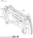
FIG. 2A depicts a front view of an exemplary backhoe tilting attachment.
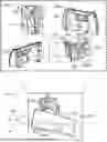
FIG. 2B depicts a close-up view of the attachment interface between the backhoe linkage and the stationary rear portion of the backhoe tilting attachment.
FIG. 2C depicts a close-up view of the attachment interface between the bucket and the rotatable front portion of the backhoe tilting attachment.
FIG. 3A depicts an elevated view of the backhoe tilting attachment coupled to a backhoe linkage.
FIG. 3B depicts a front perspective view of the backhoe tilting attachment.
FIG. 3C depicts a rear perspective view of the backhoe tilting attachment.
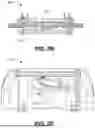
FIG. 4A depicts a front exploded view of the backhoe tilting attachment.
FIG. 4B depicts a rear exploded view of the backhoe tilting attachment.
FIG. 5 depicts a system diagram of the backhoe tilting attachment including structural, hydraulic, electrical, and sensing components.
Like reference symbols in the various drawings indicate like elements.
DETAILED DESCRIPTION OF ILLUSTRATIVE EMBODIMENTS
Apparatus and associated methods relate to a backhoe loader bucket rotator tilting attachment. In an illustrative example, the backhoe loader bucket rotating tilting attachment may connect to a quick coupler, enhancing its utility and flexibility. In some embodiments, the backhoe tilting attachment mechanism may allow the bucket to rotate approximately up to 20 degrees to the left and right. The tilting may, for example, advantageously be used in tasks requiring precise angle adjustments such as leveling ground, cutting bar ditches, or handling sloped materials.
For example, the inclusion of a piston in the backhoe tilting attachment mechanism may allow the backhoe loader bucket to tilt up to 20 degrees left and right. This functionality of the backhoe tilting attachment mechanism may be important for efficiently managing materials and contouring landscapes in environments with uneven terrain. The ability of the backhoe tilting attachment mechanism to adjust the bucket's angle may, for example, enhance operational precision. The improved operational precision may, for example, improve productivity on complex landscaping and construction projects. The versatility of the backhoe tilting attachment mechanism may, for example, advantageously allow earthwork to be performed where terrain conditions are challenging and/or require frequent positional adjustments of the bucket.
FIG. 1 depicts an exemplary backhoe tilting attachment employed in an illustrative use-case scenario 100. The scenario 100 includes a user 105 operating a backhoe outfitted with a tilting attachment 115. A bucket 110 is shown attached to the front of the attachment and is capable of rotating through an angular offset 110c around a longitudinal axis of axis of the bucket. The angular change occurs relative to a ground-based axis 110b, facilitating operations on uneven terrain. As the bucket rotates, its center 110d may shift and also translate vertically along direction 110e. A front bar 130, part of the rotatable interface, provides an additional point of structural support. The rotatable section connects to a pivot point 135, which interfaces the front assembly with rear stationary components. The rear stationary portion 145 includes apertures 145a and 145b for fasteners to mount the attachment to backhoe linkage 150. A rear hook 145c may aid in stabilizing the entire attachment structure. Hydraulic tubes 140a route fluid to piston 140, which actuates the tilting motion of the bucket.
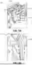
FIG. 2A presents a front view of the tilting attachment 200. A rear plate 205 serves as the main mounting structure and provides structural support for the rear connection to the backhoe. Affixed to the rear plate is a rear bar connector 210 that engages with the bar system for mechanical stability. A central pivot 215 connects the rear and front sections of the attachment and enables rotation around a central axis. A reinforcing bar 220 spans the width of the attachment to enhance rigidity during tilting motions. Hooks 225 are located near the lower edge and permit stable mechanical linkage to the backhoe, allowing for quick attachment and detachment in field use.
FIG. 2B shows a top view of the attachment 250. From this vantage point, rear bar connector 210 and rear plate 205 are clearly visible, illustrating their alignment in handling torsional forces during operation. The layout also emphasizes how the central axis remains unobstructed, preserving rotational freedom. The configuration is designed to evenly distribute stress across the mounting system and prevent material fatigue.
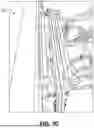
FIG. 2C illustrates a rear view of the attachment's front side 275. The piston 280 is positioned to apply force directly into the central pivot 215, converting hydraulic input into controlled angular displacement. This spatial configuration ensures efficient energy transfer and simplifies maintenance. The use of a centrally mounted actuator supports balanced tilting, important for applications requiring precise grading.
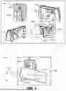
FIG. 3A shows an elevated rear view 305 of a backhoe tilting attachment coupled to a backhoe. The bucket 310 is mounted at the frontmost interface of the attachment. A rod 325 extends rearward from the bucket and is coupled to a front portion of the plate series 320, which forms the core of the tilting mechanism. The plate series 320 provides the primary structural interface for tilt control and enables rotation when actuated. The lower backhoe linkage 330 and upper backhoe linkage 335 are also visible, supporting the mechanical integration of the attachment with the backhoe arm. These linkages transmit force and allow the attachment to articulate properly during operation.
FIG. 3B provides a close-up view 315 of the interface between the bucket 310 and the tilting attachment. The front end of the plate series 320 interfaces directly with the rod 325 extending from the bucket. This connection supports the transmission of force from the actuator mechanism to the bucket, allowing for smooth and repeatable tilting motions. The arrangement helps preserve alignment and control, especially under lateral or off-axis loads during excavation or grading tasks.
FIG. 3C offers a rearward perspective 350 of the mounted tilting attachment, focusing on the layout of hydraulic components. The piston alignment is shown in relation to the structural members and the route of hydraulic tubing. The assembly demonstrates how power and control are transmitted from the vehicle's interface to the bucket.
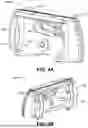
FIG. 4A portrays a front perspective 400 of the backhoe tilting attachment. Rear plate 405 is affixed to the backhoe and supports the rear components. Linkage 410 connects this plate to the rest of the backhoe. A central pivot 415 bridges the rear and front sections, providing a rotational axis. Piston 420 converts hydraulic force into angular displacement. Linkage 425 and linkage 430 coupled to a bucket which rotates with the actuation of the bucket from the pistons. FIG. 4B provides a rear perspective 440 of the same attachment. A front plate 435 reinforces the structure of the forward section.
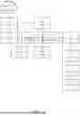
FIG. 5 illustrates a system-level diagram 500 of a modular backhoe tilting attachment integrated with hydraulic, structural, sensing, and control elements. A backhoe 505 provides the base platform and connects to a stationary rear mounting plate 510 through a backhoe linkage 515. The stationary rear mounting plate 510 is fixed relative to the backhoe and supports a rotatable front mounting plate 520 via a pivot joint. The rotatable plate 520 is in mechanical communication with the bucket 530 and is driven by a piston 535 positioned transversely between the plates. A plate linkage 525 transmits actuator force from the piston 535 to the rotating front mounting plate 520, enabling lateral tilt of the bucket 530.
The actuator is controlled via a controller 535 that also interfaces with a visual indicator 555. The visual indicator 555 is configured to provide the operator with real-time feedback on the bucket's rotational tilt relative to a neutral position. The piston 535, positioned offset from the longitudinal axis, delivers motive force for tilting through hydraulic actuation. The system further incorporates a level angle sensor 540 mounted in association with the bucket 530. This sensor monitors tilt orientation during operation to support grading and alignment tasks.
A laser sensor 545 is coupled to the bucket 530 and configured to emit a beam toward the ground level 550. This allows the system to detect and evaluate ground elevation in real time, providing terrain-conforming control inputs to the actuator via the controller 535. The feedback loop formed by the laser sensor 545, level angle sensor 540, and visual indicator 555 enables adaptive and accurate tilt adjustments across varied site conditions. This integrated configuration enhances operator awareness, control precision, and operational safety during trenching, grading, or sloped excavation.
Although various embodiments have been described with reference to the figures, other embodiments are possible.
Although an exemplary system has been described with reference to FIGS. 1A-5, other implementations may be deployed in other industrial, scientific, medical, commercial, and/or residential applications.
In some embodiments, the backhoe tilting attachment may be equipped with a sensor system that provides real-time feedback on the tilt angle and soil resistance. This backhoe tilting attachment feature may enhance precision in landscaping projects, allowing for more accurate grading and sculpting of land. The backhoe tilting attachment may include customizable control settings, which may, for example, be adjusted according to the specific needs of the terrain or the operator's preferences.
In some embodiments, the backhoe tilting attachment may be designed with a quick-release mechanism, making it easier to switch between different tools or attachments without downtime. The backhoe tilting attachment may, for example, come with reinforced joints that increase durability, especially useful in rough landscaping environments. This backhoe tilting attachment configuration may lead to improved efficiency and reduced wear and tear, thereby extending the lifespan of the equipment.
In some embodiments, the backhoe tilting attachment may feature an integrated laser leveling system. This backhoe tilting attachment would help operators set the exact angle needed for tasks like creating drainage slopes or adjusting soil depth for planting. The backhoe tilting attachment may, for example, provide feedback through a visual display interface that guides the operator during the adjustment process. The backhoe tilting attachment may include memory settings that store preferred configurations for various tasks, streamlining workflow for recurring projects. this backhoe tilting attachment may be capable of automatic adjustments based on the detected soil type and consistency, enhancing adaptability. Such a backhoe tilting attachment may, for example, dramatically increase the precision and efficiency of landscaping tasks.
In some embodiments, the backhoe tilting attachment may be designed for minimal environmental impact. This backhoe tilting attachment may use bio-based hydraulic fluids that are less harmful to the environment. The backhoe tilting attachment may feature noise reduction technology, making it suitable for use in residential areas or near noise-sensitive environments like schools and hospitals. Enhanced cushioning in the backhoe tilting attachment's mechanisms may minimize vibrations. This backhoe tilting attachment may, for example, be battery powered. may, for example,
In some embodiments, the in some land scaping equipment the tilting attachment may, for example, include be configured to specialized tools such as rippers and/or augers. This backhoe tilting attachment design would enable the operator to perform a wider range of tasks, from breaking hard ground to drilling holes for planting large trees. The backhoe tilting attachment may offer hydraulic extensions that enhance reach and flexibility. Moreover, the backhoe tilting attachment may, for example, be fitted with different sizes and shapes of buckets to match specific tasks, such as narrow buckets for trenching or wider buckets for bulk earthmoving. The backhoe tilting attachment may be compatible with various types of quick coupler systems, facilitating easy interchangeability. Such versatility of the backhoe tilting attachment makes it a highly useful tool in diverse landscaping applications.
In some embodiments, the backhoe tilting attachment may be equipped with an advanced telemetry system to track usage and maintenance needs. This backhoe tilting attachment feature may help in scheduling regular maintenance, ensuring the attachment operates at peak efficiency. The backhoe tilting attachment may include GPS tracking, useful for large-scale landscaping projects where equipment management is important. Moreover, the backhoe tilting attachment may, for example, offer wireless connectivity to sync with mobile devices or central management systems. This connectivity in the backhoe tilting attachment may allow for remote diagnostics and firmware updates, enhancing operational convenience. Such technological integrations in the backhoe tilting attachment may, for example, significantly boost productivity and maintenance efficiency.
In some embodiments, the backhoe tilting attachment may have enhanced load-bearing capabilities to handle heavier loads without compromising safety or efficiency. This backhoe tilting attachment may include a double-acting hydraulic system, providing stronger and more reliable movement.
In some embodiments, the backhoe tilting attachment may, for example, feature an automatic balancing system that adjusts the load distribution based on the current tilt angle and weight of the material.
In some embodiments, the backhoe tilting attachment may, for example, incorporate safety locks that engage automatically when the attachment is in a precarious position. These features in the backhoe tilting attachment may, for example, ensure that the backhoe tilting attachment may, for example, handle demanding tasks safely and efficiently.
In some embodiments, the backhoe tilting attachment may come with customizable skins or covers that protect against rust and dirt, while allowing companies to brand their equipment. This backhoe tilting attachment option may appeal to businesses looking to maintain a clean and professional image.
In some embodiments the backhoe tilting attachment may, for example, may, for example, include built-in lighting systems for safe operation in low-light conditions. This backhoe tilting attachment may feature a tool-less adjustment mechanism, enabling operators to make quick modifications in the field without needing additional equipment.
In some embodiments, the backhoe tilting attachment may offer enhanced compatibility with older as well as newer models of backhoes. This backhoe tilting attachment may include adaptable fittings that may, for example, connect with various hydraulic systems, ensuring wide usability. The backhoe tilting attachment may, for example, have an adjustable base plate that aligns with different backhoe models, making it a universal solution. Furthermore, this backhoe tilting attachment may feature a simple yet robust locking mechanism that secures it firmly in place during operation. The ease of installation and removal of the backhoe tilting attachment would be highly appreciated by operators who need to switch between different equipment frequently.
In some embodiments, the backhoe tilting attachment may be designed with a focus on ergonomic operation to reduce operator fatigue. This backhoe tilting attachment may feature controls that are intuitive and easy to reach, minimizing strain during long hours of operation. The backhoe tilting attachment may, for example, offer adjustable control sensitivity, allowing operators to fine-tune how responsive the attachment is to inputs. the backhoe tilting attachment may have vibration dampening handles, depending on the backhoe configuration and seat configuration of the seat of the backhoe, to reduce the physical impact on the operator. An ergonomically designed seat that complements the backhoe tilting attachment may be included to ensure comfort throughout the workday. These ergonomic enhancements in the backhoe tilting attachment would contribute to better operator health and productivity.
In some embodiments, the backhoe tilting attachment and/or attached backhoe may include a built-in safety system that alerts the operator to potential hazards, such as an overload or mechanical failure. This backhoe tilting attachment may, for example, incorporate sensors that monitor stress levels and operational conditions in real-time. The backhoe tilting attachment may, for example, include a fail-safe mechanism that automatically stops the attachment if important thresholds are exceeded. The backhoe tilting attachment may, for example, provide auditory and visual warnings to the operator when adjustments are needed to prevent accidents.
In some embodiments, the backhoe tilting attachment may explicitly specify environmental limitations, weight capacities, and compatibility with various backhoe models. For instance, the attachment may be designed to function effectively within a temperature range of −10° C. to 50° C., ensuring optimal performance under diverse weather conditions, the backhoe tilting attachment may, for example, handle loads up to approximately 6,000 kilograms, suitable for heavy-duty operations as seen in some larger backhoe models. The backhoe tilting attachment may, for example, require a hydraulic system capable of providing at least 2000 psi to operate efficiently.
In industrial applications, the backhoe tilting attachment mechanism may, for example, enhance the precision in placing heavy equipment in confined factory settings. The backhoe tilting attachment mechanism may allow for exact positioning of materials at specific angles, necessary for assembly lines and industrial installations. The backhoe tilting attachment mechanism may enable operators to safely maneuver bulky items over obstacles, minimizing workplace accidents, the backhoe tilting attachment mechanism may assist in the precise installation of complex machinery, contributing to streamlined industrial processes. Furthermore, the backhoe tilting attachment mechanism may facilitate the demolition of outdated structures, allowing for controlled and efficient removal of debris. The flexibility provided by the backhoe tilting attachment mechanism may overall improve productivity and safety in various industrial tasks.
In scientific applications, the backhoe tilting attachment mechanism may precisely position experimental apparatus in field studies. The backhoe tilting attachment mechanism may adjust large scientific instruments delicately, important for sensitive environmental research projects. The backhoe tilting attachment mechanism may facilitate the gentle reshaping of land in ecological restoration efforts, ensuring minimal disruption to existing habitats. Moreover, the backhoe tilting attachment mechanism may aid in constructing controlled experimental setups, offering stability and precision. The backhoe tilting attachment mechanism may be utilized in geological surveys to efficiently modify terrain for better access and sampling. This precision and versatility of the backhoe tilting attachment mechanism may be invaluable across diverse scientific fields.
In medical applications, the backhoe tilting attachment mechanism may be important for the precise excavation required to build foundations for new healthcare facilities. The backhoe tilting attachment mechanism may assist in landscaping and grading paths for better accessibility to medical buildings. The backhoe tilting attachment mechanism may enable the installation of outdoor medical equipment, contributing to expanded healthcare services, the backhoe tilting attachment mechanism may be used in creating therapeutic gardens, where precise contouring of the landscape is necessary. The backhoe tilting attachment mechanism may facilitate quick modifications to the terrain in emergency scenarios, improving response times. The precision and adaptability of the backhoe tilting attachment mechanism may therefore play an important role in enhancing medical infrastructure and patient care environments.
In commercial applications, the backhoe tilting attachment mechanism may streamline the construction of commercial properties by facilitating precise grading and site preparation. The backhoe tilting attachment mechanism may enhance the installation of underground utilities, which is important for building developments. The backhoe tilting attachment mechanism may allow for the accurate placement of decorative elements in commercial landscapes, improving aesthetic and functional aspects, the backhoe tilting attachment mechanism may assist in adjusting terrain for better drainage solutions in parking lots and other commercial outdoor spaces. The backhoe tilting attachment mechanism may further contribute to the modification of entrances and exits for commercial complexes, ensuring compliance with safety standards. The utility and precision of the backhoe tilting attachment mechanism may thus be integral to successful commercial construction projects.
In residential applications, the backhoe tilting attachment mechanism may assist homeowners in precise gardening and landscaping projects. The backhoe tilting attachment mechanism may allow for accurate shaping of land for home gardens, enhancing both beauty and utility. The backhoe tilting attachment mechanism may facilitate the installation of residential water features, such as ponds or fountains, requiring delicate excavation, the backhoe tilting attachment mechanism may be used in leveling ground for outdoor living spaces, ensuring stability and comfort. The backhoe tilting attachment mechanism may further help in creating effective drainage systems around residential properties, preventing water damage. The adaptability and precision of the backhoe tilting attachment mechanism may thus be essential in transforming and maintaining residential landscapes.
In some embodiments, the backhoe tilting attachment may be implemented to assist operators in achieving even grades on terrain with minimal repositioning of the machine. This functionality may allow the bucket to maintain a consistent angle despite underlying ground irregularities. Such a feature may reduce the need for repeated passes and manual corrections, which may result in improved grading accuracy and time efficiency during field operations.
In some embodiments, the tilting attachment may be integrated to support a broader range of attachments beyond conventional buckets. For example, the tilting mechanism may allow for precise angular control when using brooms, forks, or demolition tools. This may advantageously convert a standard backhoe into a more versatile multi-tool platform, eliminating the need for dedicated machines and reducing capital costs.
In some embodiments, the backhoe tilting attachment may serve as a substitute for larger grading equipment in tight or confined job sites. For instance, the tilting capability may simulate the functions of a Gannon box or small motor grader when operated by a skilled user. This may be particularly useful in urban infrastructure or agricultural settings where space is limited but precise leveling or shaping is required.
In some embodiments, the attachment may enhance the functionality of backhoes in agricultural operations. Tasks such as material relocation on ungraded farmland may benefit from the tilt feature, which can compensate for slope variability. As a result, operators may avoid damage to packaging materials or crops by maintaining proper load orientation.
In some embodiments, the attachment may allow the bucket to compress or stack materials by controlling the tilt angle precisely. For example, when loading trailers or containers with bags or loose items, the ability to angle and press loads can result in denser packing. This may reduce transportation costs by maximizing the amount of material loaded per trip.
In some embodiments, operators may experience reduced physical fatigue due to fewer required repositioning maneuvers during leveling or trenching operations. The ergonomic benefit of tilt control may lead to improved jobsite productivity and reduced machine wear, as the bucket can make finer angle corrections without moving the whole backhoe.
In some embodiments, the tilting attachment may improve operation on sloped terrain by keeping the bucket level during insertion or extraction. This may prevent damage to attached implements or carried materials and may improve safety during maneuvering. In particular, the feature may be helpful for precision loading in uneven storage yards or construction staging areas.
In some embodiments, the attachment may provide a cost-effective alternative to specialized equipment such as reach forks or telehandlers. By retrofitting tilt functionality into standard backhoes, contractors may expand machine capabilities while maintaining a smaller fleet size. This approach may be especially advantageous for small-to-medium operators needing flexible and mobile solutions.
In some embodiments, the backhoe tilting attachment may include a visual indication mechanism configured to display the real-time tilt angle of the rotatable portion relative to a neutral reference. This visual indicator may be positioned within the operator's line of sight-either mounted directly on the attachment or integrated into the cab interface-enabling immediate feedback during grading, leveling, or excavation tasks. The indication may be analog (e.g., inclinometer) or digital (e.g., LED readout), and may allow operators to maintain precise control without relying on external measurement tools or manual estimation. This visual feedback feature may reduce correction passes and enhance operator efficiency, particularly when working on sloped or irregular terrain.
In some embodiments, the backhoe tilting attachment may be constructed with interchangeable stationary and rotatable subassemblies, enabling field-based service or configuration changes without dismounting the attachment from the backhoe. This modularity may address longstanding challenges in equipment downtime by enabling rapid adaptation or repair using pre-calibrated swappable parts.
In some embodiments, the actuator may include dual-rod hydraulic cylinders oriented in a crossed or opposed configuration to balance lateral loading during tilt operation. This may enhance stability during operation and allow the attachment to maintain uniform force distribution, even when lifting offset loads. The improved control may benefit applications such as trenching on embankments or grading along foundation edges.
In some embodiments, the pivot joint may include self-lubricating composite bushings or spherical bearings designed to tolerate contamination from jobsite debris while maintaining tilt accuracy. Such pivot designs may extend service life and reduce the frequency of maintenance interventions, which is especially valuable in remote or high-duty-cycle applications.
In some embodiments, the hooks and apertures on both stationary and rotatable portions may be dimensioned to accommodate third-party linkage geometries in compliance with standardized backhoe interfaces (e.g., JRB, Wain-Roy, or custom OEM mounts). This compatibility may enable retrofitting across existing fleets, addressing the long-felt need for modular upgrades that don't require bespoke machine-pairing.
In some embodiments, the fluid conduits may include quick-connect fittings and flow control valves that allow operators to adjust tilt speed or response time. This level of control may be especially useful when transitioning between tasks requiring fine grading and those needing rapid bucket orientation, improving operational efficiency.
In some embodiments, the ±19-degree tilt limit may be selectively expanded by replacing the actuator or adjusting the frame geometry. For example, optional linkage geometries may permit future tilt ranges of up to ±30 degrees. This upgradability may serve contractors operating in environments with evolving job requirements or steeper terrain conditions.
In some embodiments, the tilting attachment may be integrated with onboard or external angle sensors to provide real-time feedback to the operator via a visual or auditory interface. Such feedback may enhance grading precision and reduce over-correction, especially in low-visibility or high-fatigue conditions.
A number of implementations have been described. Nevertheless, it will be understood that various modifications may be made. For example, advantageous results may be achieved if the steps of the disclosed techniques were performed in a different sequence, or if components of the disclosed systems were combined in a different manner, or if the components were supplemented with other components. Accordingly, other implementations are contemplated within the scope of the following claims.
Claims
What is claimed is:1. A modular backhoe tilting attachment comprising:
a modular frame extending along a longitudinal axis between a proximal end configured for fixed coupling to a backhoe linkage and a distal end configured to support a bucket;
a stationary portion at the proximal end of the frame comprising a first pair of opposing hooks and a first pair of opposing apertures, each pair positioned on opposite radial sides of the longitudinal axis and configured to engage linkage elements from the backhoe such that the stationary portion remains fixed against rotation relative to the backhoe;
a rotatable portion mounted at the distal end of the frame, the rotatable portion comprising a second pair of opposing hooks and a second pair of opposing apertures, each pair positioned on opposite radial sides of the longitudinal axis and configured to engage and retain the bucket at multiple contact points;
a pivot joint aligned coaxially with the longitudinal axis and positioned between the stationary and rotatable portions;
at least one actuator laterally offset from the longitudinal axis and extending transversely between the stationary and rotatable portions, the actuator configured such that actuation causes the rotatable portion to rotate selectively up to a predetermined angle relative to a neutral position; and,
fluid conduits connected to the actuator configured to be in fluid communication with a fluid actuation system of a backhoe and operable via a control interface.
2. The modular backhoe tilting attachment of claim 1, wherein the actuator is configured to rotate the rotatable plate up to approximately ±19 degrees from a neutral position.
3. The modular backhoe tilting attachment of claim 1, wherein the actuator comprises a hydraulic piston mounted transversely between the stationary plate and the rotatable plate.
4. The modular backhoe tilting attachment of claim 1, wherein the fluid conduits comprise a pair of hydraulic hoses connected to the actuator via quick-connect fittings.
5. The modular backhoe tilting attachment of claim 1, wherein the pivot joint comprises a cylindrical bearing assembly aligned with the longitudinal axis between the stationary plate and the rotatable plate.
6. The modular backhoe tilting attachment of claim 1, further comprising a visual indicator coupled to the rotatable plate and configured to display the current rotational angle relative to the stationary plate to an operator during operation.
7. The modular backhoe tilting attachment of claim 1, wherein the actuator is configured to return the rotatable plate to the neutral position upon loss of hydraulic pressure.
8. The modular backhoe tilting attachment of claim 1, further comprising a mechanical stop coupled to the modular frame and positioned to limit rotation of the rotatable plate beyond a predefined angular range.
9. The modular backhoe tilting attachment of claim 1, wherein the modular frame comprises a removable connector interface enabling detachment of the rotatable plate from the stationary plate.
10. The modular backhoe tilting attachment of claim 1, wherein the first pair of opposing apertures on the stationary plate are configured to receive locking pins that secure the attachment to the backhoe linkage.
11. The modular backhoe tilting attachment of claim 1, wherein the second pair of opposing hooks on the rotatable plate are configured to engage a quick-attach bracket of a bucket.
12. The modular backhoe tilting attachment of claim 1, wherein the actuator is mounted on a lower side of the modular frame and is offset vertically beneath the pivot joint.
13. The modular backhoe tilting attachment of claim 1, wherein the stationary plate further comprises a beveled alignment guide configured to assist with mating to a backhoe linkage.
14. The modular backhoe tilting attachment of claim 1, wherein the actuator comprises an internal fluid damper configured to absorb transient forces during tilting of the rotatable plate.
15. The modular backhoe tilting attachment of claim 1, wherein the modular frame comprises a steel alloy body structured to resist torsional forces transferred between the stationary plate and the rotatable plate.
16. The modular backhoe tilting attachment of claim 1, further comprising a laser-based sensor system mounted to the frame and configured to measure and transmit ground elevation data in real-time to support terrain-conforming tilt operation of the rotatable plate.
17. The modular backhoe tilting attachment of claim 1, wherein the actuator is manually operable through a user interface configured to incrementally adjust the tilt angle of the rotatable plate relative to the stationary plate.
18. The modular backhoe tilting attachment of claim 1, wherein the actuator is removably attached to both the stationary plate and the rotatable plate by pin connections.
19. The modular backhoe tilting attachment of claim 1, wherein the pivot joint is integrally formed as a unitary element of the modular frame for coaxial alignment of the stationary plate and rotatable plate.
20. A modular backhoe tilting system comprising:
a backhoe comprising a linkage and a control interface; and
a modular backhoe tilting attachment comprising:
a modular frame extending along a longitudinal axis between a proximal end configured for fixed coupling to the backhoe linkage and a distal end configured to support a bucket;
a stationary portion at the proximal end of the frame comprising a first pair of opposing hooks and a first pair of opposing apertures, each pair positioned on opposite radial sides of the longitudinal axis and configured to engage linkage elements from the backhoe such that the stationary portion remains fixed against rotation relative to the backhoe;
a rotatable portion mounted at the distal end of the frame, the rotatable portion comprising a second pair of opposing hooks and a second pair of opposing apertures, each pair positioned on opposite radial sides of the longitudinal axis and configured to engage and retain the bucket at multiple contact points;
a pivot joint aligned coaxially with the longitudinal axis and positioned between the stationary and rotatable portions;
at least one actuator laterally offset from the longitudinal axis and extending transversely between the stationary and rotatable portions, the actuator configured such that actuation causes the rotatable portion to rotate selectively up to a predetermined angle relative to a neutral position; and
fluid conduits connected to the actuator, the fluid conduits in fluid communication with a fluid actuation system of the backhoe and operable via the control interface.
Images & Drawings included:
Sources:
- United States Patent and Trademark Office - verify current appl. status at the USPTO↗
Recent applications in this class:
- » 20250188701 2025-06-12
ADVANCED PRECISION CONSTRUCTION FEATURES ON PILOT OPERATED MACHINES - » 20250019922 2025-01-16
Construction Machine - » 20240209589 2024-06-27
SHOVEL - » 20240141613 2024-05-02
MODULAR EXCAVATOR - » 20240110358 2024-04-04
WORKING MACHINE - » 20220267982 2022-08-25
WALKING EXCAVATOR - » 20220081870 2022-03-17
Excavator - » 20200157764 2020-05-21
Shovel - » 20190360168 2019-11-28
Hydraulic excavator - » 20190211526 2019-07-11
Shovel