Measuring Wellhead Displacement Using Shadowgraphy
US20260028895A1
2026-01-29
18/782,805
2024-07-24
Smart Summary: Measuring wellhead displacement can be done without direct contact using a technique called shadowgraphy. This involves capturing an image of a shadow created by part of the wellhead blocking infrared light. The shadow shows interference patterns that help identify the edge of the wellhead. By comparing the current position of this edge to where it was previously, the movement of the wellhead can be determined. This method is effective because it uses infrared light that doesn't get absorbed by water or affected by sunlight. 🚀 TL;DR
Abstract:
Systems and methods for performing contactless wellhead displacement measurements include receiving a shadowgraph from an imaging sensor based on a shadow generated by a portion of a wellhead blocking light from a coherent infrared light source, the infrared light having a wavelength away from water absorption wavelengths and solar maxima wavelengths. A feature is detected in the shadowgraph based on interference patterns in the shadowgraph caused by diffraction of the light. The feature represents an edge of the portion of the wellhead. A displacement of the wellhead is measured based on the location of the feature in the shadowgraph and a previously detected location of the feature.
Inventors:
- Sameeh Issa Batarseh 83 🇸🇦 Dhahran, Saudi Arabia
- Damian Pablo San Roman Alerigi 25 🇸🇦 Al-Khobar, Saudi Arabia
Applicant:
Interested in similar patents?
Get notified when new applications in this technology area are published.
Classification:
E21B34/025 » CPC main
Valve arrangements for boreholes or wells in well heads Chokes or valves in wellheads and sub-sea wellheads for variably regulating fluid flow
E21B47/002 » CPC further
Survey of boreholes or wells by visual inspection
E21B47/06 » CPC further
Survey of boreholes or wells Measuring temperature or pressure
E21B47/09 » CPC further
Survey of boreholes or wells Locating or determining the position of objects in boreholes or wells, e.g. the position of an extending arm ; Identifying the free or blocked portions of pipes
E21B47/26 » CPC further
Survey of boreholes or wells Storing data down-hole, e.g. in a memory or on a record carrier
E21B34/02 IPC
Valve arrangements for boreholes or wells in well heads
Description
TECHNICAL FIELD
This disclosure generally relates to measuring wellhead displacement.
BACKGROUND
Wellheads and hydrocarbon production surface structures can be subject to complex forces and thermal gradients that cause structural changes or damage including, for example, anisotropic dilation, fatigue, and displacement, among others. These effects can damage the wellheads, the surface structures, or both. Conventionally, structural changes are measured manually as part of routine inspections. Times that measurements are taken may be sporadic due to the number of wells, remote locations of the wells, and weather conditions.
SUMMARY
Wellheads are a critical part of oil/gas/geothermal drilling, completion, and production systems, acting as both the structural and pressure containing interface. Wellheads include equipment mounted at the opening of the well to regulate and monitor hydrocarbon extraction from a subsurface formation, and typically includes three components: a casing head, a tubing head, and a production tree (colloquially known as a Christmas tree). The casing head can be fitted with valves and plugs to access the well casing. The tubing head can position the tubing correctly in the well and provides reliable well access. The tubing head can be sealed to enable removal of the production tree with pressure in the casing. The production tree can include multiple types of valves and gauges such as a master gate valve, a pressure gauge, a wing valve, a swab valve, and a choke and a number of check valves. The production tree provides production operation control and monitoring. The wellhead provides casing and tubing suspension, and a means to attach a blowout preventer during drilling to avoid high pressure formation induced blowouts.
During the well service life, the wellhead can undergo movement and displacement, often visually observed as a height change (e.g., growth) of the wellhead compared with a previous position. This can be caused by a host of factors including static, thermal, and pressure induced complex wellhead loadings. Wellhead growth caused by temperature and pressure effects during production could be severe and critical, causing well integrity failure and surface equipment damage, sometimes with catastrophic consequences at huge safety risks and economic losses. Being able to detection, quantify and mitigate displacement can have significant economic and safety impact to production fields.
This disclosure provides an approach for measuring wellhead displacement using shadowgraphy. The wellhead, or a portion of the wellhead, can be illuminated by an infrared light source. An illumination system including the infrared light source can be positioned on one side of the wellhead and a detection system can be positioned on the opposite side of the wellhead to receive the light from the illumination system. The wellhead, or the portion of the wellhead, can create a shadow by blocking light from reaching the detection system. Light propagating past an edge of the wellhead can diffract causing interference patterns to appear in shadowgraphs captured by the detection system. Features in the shadowgraph representing edges of the wellhead can be detected. Shadowgraphs from two or more instances of time can be used to measure a displacement of the wellhead. The wellhead displacement can be used to trigger corrective actions, for example, when the displacement exceeds a threshold displacement.
Implementations of the systems and methods of this disclosure can provide various technical benefits. A shadowgraphy approach enables submillimeter features of the wellhead to be tracked over time. The submillimeter features can be linked to the integrity of the wellhead and indicate damage (e.g., erosion, corrosion, and micro-torsions). The shadowgraphy system approach safely obtains contactless displacement measurements in hot environments and near explosive material (e.g., oil and/or natural gas). The shadowgraphy system can obtain continuous measurements in real-time. The shadowgraphy system can obtain wellhead measurements in the presence of environmental and weather based occlusions (e.g., fog, rain, light sandstorms). The shadowgraphy system can be resilient to deformations (e.g., thermal expansion, mechanical deformation) of the optical system because the shadowgraphy system can be recalibrated in place by projecting a predefined pattern. The shadowgraphy system enables monitoring degradation of surface equipment such as wellheads can reduce fugitive leaks (e.g., irregular emissions of gases or other fluids) and enable preventive maintenance of the surface equipment. Wellhead displacement data can be used to predict emissions from the wellhead.
The shadowgraphy system can be adapted for desert environments by tuning emission wavelengths away from the solar maxima and water absorption wavelengths. Optical components of the system can be mounted on moving stages that can be adjusted to compensate for thermal dilations or recoil of the optical system. The moving stages can be adjusted based on continuous monitoring of the temperature of the system and the deformation of a known pattern projected by the illumination system. The known pattern can be projected using a different wavelength of light in the mid to long wavelength infrared ranges to enable quasi-specular reflection of the pattern from the surfaces of the wellhead to monitor bulk displacements of the wellhead.
The details of one or more implementations of these systems and methods are set forth in the accompanying drawings and the description below. Other features, objects, and advantages of these systems and methods will be apparent from the description and drawings, and from the claims.
DESCRIPTION OF DRAWINGS
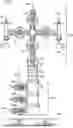
FIG. 1 is a schematic of a wellhead assembly.
FIG. 2 is an illustration of a shadowgraphy measurement system.
FIG. 3 is a block diagram of a shadowgraphy measurement system.
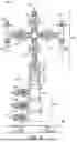
FIG. 4 is a block diagram of an illumination system and a detection system.
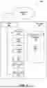
FIG. 5 is a flow chart for a method for measuring wellhead displacement.
FIG. 6 is a block diagram illustrating an example computer system used to provide computational functionalities associated with described algorithms, methods, functions, processes, flows, and procedures according to some implementations of the present disclosure.
Like reference symbols in the various drawings indicate like elements.
DETAILED DESCRIPTION
Wellheads are a critical part of oil/gas/geothermal drilling, completion, and production systems, acting as both the structural and pressure containing interface. Wellheads include equipment mounted at the opening of the well to regulate and monitor hydrocarbon extraction from a subsurface formation, and typically includes three components: a casing head, a tubing head, and a production tree (colloquially known as a Christmas tree). The casing head can be fitted with valves and plugs to access the well casing. The tubing head can position the tubing correctly in the well and provides reliable well access. The tubing head can be sealed to enable removal of the production tree with pressure in the casing. The production tree can include multiple types of valves and gauges such as a master gate valve, a pressure gauge, a wing valve, a swab valve, and a choke and a number of check valves. The production tree provides production operation control and monitoring. The wellhead provides casing and tubing suspension, and a means to attach a blowout preventer during drilling to avoid high pressure formation induced blowouts.
During the well service life, the wellhead can undergo movement and displacement, often visually observed as a height change (e.g., growth) of the wellhead compared with a previous position. This can be caused by a host of factors including static, thermal, and pressure induced complex wellhead loadings. Wellhead growth caused by temperature and pressure effects during production could be severe and critical, causing well integrity failure and surface equipment damage, sometimes with catastrophic consequences at huge safety risks and economic losses. Being able to detection, quantify and mitigate displacement can have significant economic and safety impact to production fields.
This disclosure provides an approach for measuring wellhead displacement using shadowgraphy. The wellhead, or a portion of the wellhead, can be illuminated by an infrared light source. An illumination system including the infrared light source can be positioned on one side of the wellhead and a detection system can be positioned on the opposite side of the wellhead to receive the light from the illumination system. The wellhead, or the portion of the wellhead, can create a shadow by blocking light from reaching the detection system. Light propagating past an edge of the wellhead can diffract causing interference patterns to appear in shadowgraphs captured by the detection system. Features in the shadowgraph representing edges of the wellhead can be detected. Shadowgraphs from two or more instances of time can be used to measure a displacement of the wellhead. The wellhead displacement can be used to trigger corrective actions, for example, when the displacement exceeds a threshold displacement.
FIG. 1 illustrates a wellhead assembly 100 at a surface 116 of a wellbore 120. The wellhead assembly 100 includes a casing spool 102, a production tree 104 fluidly coupled to the wellhead 102, and a tubing bonnet assembly 106 residing between and fluidly coupled to the wellhead 102 and the production tree 104. The tubing bonnet assembly 106 is attached, on a bottom end 108, to a top flange 140 of a tubing spool 142 of the wellhead 102. The tubing bonnet assembly 106 is attached, on a top end 115, to a bottom flange 130 of a valve 132 (for example, a master valve) of the production tree 104.
The wellhead assembly 100 provides a structural and pressure-containing interface between the wellbore 120 and hydrocarbon production equipment. The production tree 104 includes valves 132 to control the pressure and flow of hydrocarbons from the wellbore 120 to the hydrocarbon production equipment. The wellhead assembly 100 can be exposed to harsh environments that may result in structural changes or damage to the wellhead assembly 100 such as anisotropic dilation, fatigue, displacement, corrosion, etc. The structural changes or damage can impair the functioning of the wellhead assembly 100. Without consistent measurement and monitoring, changes or damage to the wellhead assembly 100 could be unnoticed until a failure of the wellhead assembly 100 or its subcomponents.
The casing spool 102 includes casing annulus valves 132A, 132B, and 132C are illustrated. The casing annulus valves 132A-132C control fluid flow in the annular space of wellbore 100. A pressure gauge 134 enables pressure readings at the casing spool 102.
The wellhead assembly 100 includes a system of valves, adapters, and other devices that enable pressure control of a well. In examples, the wellhead includes a Christmas tree. For example, valves above ground level 103 are arranged in a crucifix type pattern and are colloquially referred to as a Christmas tree. In some embodiments, a Christmas tree is an assembly of valves, casing spools, and fittings used to regulate the flow of pipes in an oil well, gas well, water injection well, water disposal well, gas injection well, condensate well, and other types of well. For case of description, particular components are described with respect to the wellhead assembly 100. However, the wellhead assembly 100 can include any number of components that regulate the flow of hydrocarbons. In some examples, the wellhead assembly 100 includes a frac stack, frac tree, composite frac tree, production tree, and the like.
The wellhead assembly 100 includes multiple valves. The valves include varying valve configurations and combinations of manual and/or actuated (e.g., hydraulic or pneumatic) valves. As shown in FIG. 1, two lower valves are referred to as master valves, an upper master valve 110 and lower master valve 112. The master valves 110 and 112 are in a fully open position after completion of the well and are not opened or closed when the well is flowing (except in an emergency) to prevent erosion of the valve sealing surfaces. In some embodiments, the lower master valve 112 is manually operated and the upper master valve 110 is hydraulically actuated. In some implementations, the upper master valve 110 is controlled from a remote location and enables remote shutting in of the well in the event of emergency.
The wellhead assembly 100 includes a kill wing valve 114 and a flow wing valve 116. In some embodiments, the wing valves 114 and 116 are hydraulically actuated. The flow wing valve 116 enables hydrocarbons to flow from the well, to a flowline 118. The flowline 118 defines the path that the hydrocarbons take to production facilities (or the path water or gas will take from production to the well in the case of injection wells). An emergency shutdown device 119 can be used to remotely shut in the well in case of an emergency. In examples, kill wing valve 114 is used for injection of fluids such as corrosion inhibitors or methanol to prevent hydrate formation. In some embodiments, the kill wing valve 114 is manually operated. As shown in FIG. 1, a pressure gauge 122 at the production tree 104 can be used to monitor pressure at the wellhead.
The wellhead assembly 100 also includes a swab valve 124 that is used for well interventions like wireline and coiled tubing. For such operations, a lubricator is rigged up onto the top of the production tree 104 and the wire or coil is lowered through the lubricator, past the swab valve 124 and into the well. In some examples, the swab valve 124 is manually operated. A needle valve 126 is used to start, stop, and regulate the flow rate at the wellhead. In some embodiments, the needle valve 126 enables rigging down equipment from the top of the wellhead assembly 100 with the well flowing while ensuring two barriers separate hydrocarbons from the swab valve 124.
FIG. 2 illustrates an example shadowgraphy system 200. The shadowgraphy system can be used to track the height and radial displacement of surface equipment (e.g., wellheads, production tubing, manifolds, etc.). Without limitation, the following description uses a wellhead as the surface equipment; however, the same systems and processes can be used on other types of surface equipment.
The system 200 includes an illumination system 202 that illuminates a portion of the wellhead 204. A detection system captures an image 206 of the portion of the wellhead. The detection system is located on the opposite side of the wellhead (e.g., diametrically opposed) from the illumination system 202. The wellhead 204 blocks a portion of the light forming a shadow 208 in the image 206. As the light propagates past edges of the wellhead 204, the light diffracts creating additional beams of light that can generate interference patterns. The image 206 shows both the shadow 208 and the diffracted beam. The detection system can include two portions, an interferometry portion and a schlieren portion. The interferometry portion generates a shadowgraph including interference patterns caused by diffraction of the light. The schlieren portion includes information on density variations in the fluid between the illumination system and the detection system.
The data from the interferometry portion can be analyzed, e.g., by a computer system, to determine relative displacements using, for example, time-lapse cross-correlations between a current image of the wellhead and a prior image of the wellhead. The shadowgraph in the Schlieren arm can be processed using, for example, cross-correlations and/or machine vision techniques. Timelapse data can be recorded by the computer system and later accessed to determine relative displacement of the wellhead through time. The analysis can use computer vision and deep-neural networks for quick inference. In some implementations, the displacement speed of the wellhead can be tracked using an optical flow technique, which looks at the temporal gradient of the shadow. In some implementations, the optical flow technique can be used to predict future movements of the wellhead.
Additional information can be gathered from the image 206 such as information about fluid flows 210 around the wellhead 204. The density of gases can vary substantially based on the temperature of the gas and/or the velocity of the gas. Density variations cause changes in the index of refraction of the gas. These changes can be visualized in shadowgraphs and schlieren images as contrast changes in the image intensity. When temperature is the primary contributor to density variations, the temperature of the fluid can be inferred based on the shadowgraphs and/or schlieren images.
FIG. 3 is a block diagram of an example shadowgraphy system 300. The system 300 includes a controller 302, an illumination system 304, a detection system 306, and a data processing system 312. The illumination system 304 emits coherent light 312 (e.g., light with in-phase wavelengths of the same length) to illuminate a portion of the wellhead 310. The detection system 306 receives light 314, including diffracted light beams, that has transmitted past the wellhead structure 310.
The controller 302 includes electronics to control the illumination system 304 that emits light and the detection system 306 that detects light. For example, the controller can include timers, function generators, photodetectors, analog-to-digital converters, and hardware storage devices. The controller 302 is in electronic communication with the illumination system 304, the detection system 306, and the data processing system 312. For example, the controller 302 can be hard-wired to one or more of the illumination system 304, the detection system 306, and the data processing system 312. In some implementations, the controller 302 can communicate with one or more of the illumination system 304, the detection system 306, and the data processing system 312 over a wireless communication network (e.g., cellular, Wi-Fi, short range radio communications).
The illumination system 304 includes, for example, optical elements, optomechanical mounts, electronics, and light sources (e.g., lasers or super luminescent diodes (SLDs)). The wavelength of the light sources can be, for example, in the long wavelength infrared (LWIR) range. The wavelength of light can be chosen to minimize scattering due to the roughness of the object, to reduce absorption from atmospheric gases such as water vapor, and to be away from wavelengths associated with solar radiation. Water vapor absorption wavelengths are centered at 1.38, 1.87, 2.7, 6.3, and 71 micrometers. Solar maxima wavelengths have maximum intensity around 500 nanometers and can extend from 300 nanometers to 3 micrometers. An example range of light wavelengths for the light sources includes wavelengths in the range of 8-14 micrometers. Other wavelengths can be used depending on the requirements of a particular application. An example illumination system 304 is described in more detail in reference to FIG. 4.
The detection system 306 includes, for example, optical elements, optomechanical mounts, electronics, and sensors to capture and manipulate light from the illumination system 304. The detection system 306 can include an interferometry arm and a schlieren arm to measure multiple aspects of the wellhead from the incoming light. Each of the arms of the detection system 306 can receive a portion of the received light from a beam splitter. An example detection system 306 is described in more detail in reference to FIG. 4.
The data processing system 312 can receive image data from the detection system 306. The data processing system 312 can be similar to the computer system of FIG. 6. The data processing system 312 can use the shadowgraphs, interferograms, and schlieren images generated by the illumination system 304 and detection system 306 to infer displacements of the wellhead 310 using cross-correlations, optical flow, machine vision, and/or machine learning techniques. The collected data can be further investigated by the data processing system 312 using temporal analysis or other methods (e.g., machine learning) in a post-analysis step. The data processing system 312 stores a time-lapse of the data that can be later accessed to determine relative displacement of the structure.
In some implementations, the illumination system 304 can project a known pattern of light to facilitate periodic recalibrations of the illumination system 304 and the detection system 306. Recalibration can be performed by adjusting locations of optical elements in the illumination system 304 and the detection system 306 until the projected pattern matches a calibration pattern. The optical elements can be adjusted, for example, by operating motorized optomechanical stages coupled to the optical elements to translate and/or rotate the optical elements in the system. The recalibration procedure can be controlled by the controller 302 and the data processing system 312. The recalibration process can enable the system 300 to be deployed in remote environments, e.g., desert environments, and compensate for thermal dilations of the system 300 and/or recoil of the system 300. The recalibration procedure can be performed periodically at predefined intervals and/or on an as-needed basis.
FIG. 4 is a schematic of an illumination system 304 and a detection system 306 for measuring displacements of a wellhead 310. The illumination system 304 and the detection system 306 are positioned on opposite sides of the wellhead 310. The illumination system 304 emits coherent infrared light 312 from a coherent infrared light source 400. The light 312 illuminates a portion of the wellhead 310. As the light transmits past the wellhead 310, the edges of the wellhead 310 can cause diffraction of the light. Additionally, optically opaque portions of the wellhead 310 block light from transmitting past the wellhead 310 thereby forming shadows. The light 314 that propagates past the wellhead 310 includes the diffracted beams, which can cause light interference with the original beam and/or other diffracted beams, and voids caused by the shadows.
The coherent infrared light source 400 can be, for example, an infrared laser, or an SLD. The illumination system 304 also includes optical elements 402 such as lenses, beam condensers, beam expanders, diffusers, diffractive optical elements optomechanical hardware, etc. The optical elements 402 are used to condition the light (e.g., expand, focus, collimate) for use in measuring the wellhead displacement. Diffusers enable even illumination of the wellhead which can enable collection of sub-millimeter degradation data. The diffractive optical element can be used to generate a pattern of light that is projected onto the wellhead. In some implementations, the illumination system 304 can include multiple coherent infrared light sources to illuminate multiple portions of the wellhead 310.
The detection system 306 receives the transmitted light 314 to generate shadowgraphs, interferograms, and schlieren images. The light 314 is split by a beam splitter 404 (e.g., a 50:50 beam splitter), where a first portion is transmitted to an interferometry portion 406, and a second portion is reflected to a mirror 408 and the to a schlieren portion 410.
The interferogram portion 406 includes optical elements 412 to focus the light onto a sensor 414. The sensor 414 can be, for example, a photodetector, a complementary metal-oxide semiconductor (CMOS) sensor, or a charge-coupled device (CCD) sensor. The sensor 414 captures the light and transmits the captured light to the data processing system 312. The optical elements 412 affect the type of measurements that can be taken from an acquired image. In some implementations, the optical elements 412 include an imaging lens that focuses the light onto the sensor 414. The image created in this manner includes the shadow created by the portion of the wellhead blocking the light, and diffraction interference patterns. The resulting image can be referred to as a shadowgraph and/or an interferogram.
The schlieren portion 410 includes a lens 416 to focus the light onto a Wollaston prism 418. The Wollaston prism 418 splits the light into two beams with each beam having a perpendicular polarization form the other beam, and the beams are separated by a small displacement. The light propagates to a second lens 420 that focuses or collimates the light onto a sensor 422. The two beams overlap at the sensor causing interference patterns due to phase difference between the beams. The sensor 422 can be a photodetector (or array of photodetectors), a CMOS sensor, or a CCD sensor. The image captured by the sensor 422 is transmitted to the data processing system 312. The schlieren portion 410 can also include polarizers before and after the Wollaston prism 418 (e.g., between lens 416 and the Wollaston prism 418 and between the Wollaston prism 418 and the lens 420). The polarizers can be used to tune the image captured by the sensor 422. The image generated can be referred to as a schlieren image, or alternatively, as a differential or shearing interferogram. The optical components of the schlieren portion 410 can be adjusted to form either finite fringe interferograms, or infinite fringe interferograms that approximate a schlieren image with a cutoff. The generated image can be used to track density variations along the optical path, detect fluid flows around the wellhead, and/or infer temperatures near the wellhead. A Wollaston prism enables greater control over the condition of light as compared with using a knife-edge cutoff. For example, the polarization of the light can be controlled using polarizers and the Wollaston prism.
In some implementations, the sensors 414, 422 can include an array of angle-sensitive CMOS or CCD sensors. This setup can provide the angle of incidence of the light around the perimeter of the wellhead, which can be used to track displacements of the wellhead using triangulation considering the initial position of the object and the illumination system.
FIG. 5 is a flow chart for an example method 500 for measuring displacement of a wellhead. The method 500 can be implemented on a data processing system (e.g., data processing system 312, or the computer system of FIG. 6).
The data processing system receives a shadowgraph from an imaging sensor based on a shadow generated by a portion of a wellhead blocking light from a coherent infrared light source (step 502). The shadowgraph can include interference patterns such as interference patterns caused by diffraction of the infrared light around edges of the wellhead.
The data processing system detects a feature in the shadowgraph based on interference patterns in the shadowgraph caused by diffraction of the light (step 504). The feature represents an edge of the portion of the wellhead. The feature can be detected using image processing techniques, such as edge detection or image segmentation. Alternatively, or additionally, the data processing system can detect the feature using a machine learning model, e.g., a convolutional neural network or a deep neural network, that is trained to identify the feature. The machine learning model can be trained based on shadowgraphs obtained from a wellhead measurement system (e.g., system 300) labeled with the feature location.
The data processing system measures a displacement of the wellhead based on the location of the feature in the shadowgraph and a previously detected location of the feature (step 506). The data processing system can measure the displacement of the wellhead based on performing a cross-correlation between the shadowgraph and a previously acquired shadowgraph or using a trained machine learning model.
In some implementations, the data processing system can receive a schlieren image of the portion of the wellhead from a second imaging sensor. The schlieren image can be generated by the light from the coherent infrared light source being focused onto a Wollaston prism. The data processing system can measure the displacement of the wellhead using the schlieren image and a previously obtained schlieren image. The data processing system can measure the displacement using a cross-correlation technique and/or by using a trained machine learning model. The data processing system can compare the displacement measured with the schlieren image with the displacement measured with the shadowgraph.
In some implementations, the data processing system determines a temperature near the wellhead based on the schlieren image. For example, the data processing system determines a value associated with a density gradient in the schlieren image. The data processing system can determine the temperature based on the density gradient.
In some implementations, the data processing system iteratively measures displacements of the portion of the wellhead at multiple instances of time to generate a time-history of the displacements. The time-history of displacements can be used to assess the movement of the wellhead over time. The data processing system can determine a displacement speed of the wellhead over time based on the time-history of displacements. The time-history can be used to identify anomalies in the wellhead and/or changes in the performance or condition of the wellhead. The data processing system can predict anomalies of the wellhead using a machine learning model that takes as input the time-history of the displacements and outputs the location and/or the severity of the anomalies.
In some implementations, the data processing system can predict future movements of the wellhead based on the time-history of the displacements. For example, the data processing system can use optical flow techniques to identify a temporal gradient in the shadow of the wellhead in the shadowgraph. Based on the temporal gradient of the shadow, the data processing system can predict future movements of the wellhead. Machine learning models, such as recurrent neural networks, can be used to analyze patterns and predict the future states of the wellhead. In some implementations, the predictive model can use additional data from, for example, production of hydrocarbons through the wellhead and environmental factors such as temperature, pressure, and flow type.
In response to determining that the displacement exceeds a threshold displacement, the data processing system can perform a corrective action (step 508) to remedy the detected displacement. For example, the data processing system can generate an alert that the displacement exceeds the threshold displacement. The data processing system can generate an audio alert, a visual alert or both. The alert can indicate a preventive maintenance task to be performed by personnel. In some implementations, the data processing system can adjust valve positions to reduce the flow of hydrocarbons in the wellhead based on determining that the displacement exceeds the threshold displacement.
FIG. 6 is a block diagram of an example computer system 600 used to provide computational functionalities associated with described algorithms, methods, functions, processes, flows, and procedures described in the present disclosure, according to some implementations of the present disclosure. The illustrated computer 602 is intended to encompass any computing device such as a server, a desktop computer, a laptop/notebook computer, a wireless data port, a smart phone, a personal data assistant (PDA), a tablet computing device, or one or more processors within these devices, including physical instances, virtual instances, or both. The computer 602 can include input devices such as keypads, keyboards, and touch screens that can accept user information. Also, the computer 602 can include output devices that can convey information associated with the operation of the computer 602. The information can include digital data, visual data, audio information, or a combination of information. The information can be presented in a graphical user interface (UI) (or GUI).
The computer 602 can serve in a role as a client, a network component, a server, a database, a persistency, or components of a computer system for performing the subject matter described in the present disclosure. The illustrated computer 602 is communicably coupled with a network 630. In some implementations, one or more components of the computer 602 can be configured to operate within different environments, including cloud-computing-based environments, local environments, global environments, and combinations of environments.
At a high level, the computer 602 is an electronic computing device operable to receive, transmit, process, store, and manage data and information associated with the described subject matter. According to some implementations, the computer 602 can also include, or be communicably coupled with, an application server, an email server, a web server, a caching server, a streaming data server, or a combination of servers.
The computer 602 can receive requests over network 630 from a client application (for example, executing on another computer 602). The computer 602 can respond to the received requests by processing the received requests using software applications. Requests can also be sent to the computer 602 from internal users (for example, from a command console), external (or third) parties, automated applications, entities, individuals, systems, and computers.
Each of the components of the computer 602 can communicate using a system bus 603. In some implementations, any or all of the components of the computer 602, including hardware or software components, can interface with each other or the interface 604 (or a combination of both), over the system bus 603. Interfaces can use an application programming interface (API) 612, a service layer 613, or a combination of the API 612 and service layer 613. The API 612 can include specifications for routines, data structures, and object classes. The API 612 can be either computer-language independent or dependent. The API 612 can refer to a complete interface, a single function, or a set of APIs.
The service layer 613 can provide software services to the computer 602 and other components (whether illustrated or not) that are communicably coupled to the computer 602. The functionality of the computer 602 can be accessible for all service consumers using this service layer. Software services, such as those provided by the service layer 613, can provide reusable, defined functionalities through a defined interface. For example, the interface can be software written in JAVA, C++, or a language providing data in extensible markup language (XML) format. While illustrated as an integrated component of the computer 602, in alternative implementations, the API 612 or the service layer 613 can be stand-alone components in relation to other components of the computer 602 and other components communicably coupled to the computer 602. Moreover, any or all parts of the API 612 or the service layer 613 can be implemented as child or sub-modules of another software module, enterprise application, or hardware module without departing from the scope of the present disclosure.
The computer 602 includes an interface 604. Although illustrated as a single interface 604 in FIG. 6, two or more interfaces 604 can be used according to particular needs, desires, or particular implementations of the computer 602 and the described functionality. The interface 604 can be used by the computer 602 for communicating with other systems that are connected to the network 630 (whether illustrated or not) in a distributed environment. Generally, the interface 604 can include, or be implemented using, logic encoded in software or hardware (or a combination of software and hardware) operable to communicate with the network 630. More specifically, the interface 604 can include software supporting one or more communication protocols associated with communications. As such, the network 630 or the interface's hardware can be operable to communicate physical signals within and outside of the illustrated computer 602.
The computer 602 includes a processor 605. Although illustrated as a single processor 605 in FIG. 6, two or more processors 605 can be used according to particular needs, desires, or particular implementations of the computer 602 and the described functionality. Generally, the processor 605 can execute instructions and can manipulate data to perform the operations of the computer 602, including operations using algorithms, methods, functions, processes, flows, and procedures as described in the present disclosure.
The computer 602 also includes a database 606 that can hold data for the computer 602 and other components connected to the network 630 (whether illustrated or not). For example, database 606 can hold data 616 (e.g., resistivity data). For example, database 606 can be an in-memory, conventional, or a database storing data consistent with the present disclosure. In some implementations, database 606 can be a combination of two or more different database types (for example, hybrid in-memory and conventional databases) according to particular needs, desires, or particular implementations of the computer 602 and the described functionality. Although illustrated as a single database 606 in FIG. 6, two or more databases (of the same, different, or combination of types) can be used according to particular needs, desires, or particular implementations of the computer 602 and the described functionality. While database 606 is illustrated as an internal component of the computer 602, in alternative implementations, database 606 can be external to the computer 602.
The computer 602 also includes a memory 607 that can hold data for the computer 602 or a combination of components connected to the network 630 (whether illustrated or not). Memory 607 can store any data consistent with the present disclosure. In some implementations, memory 607 can be a combination of two or more different types of memory (for example, a combination of semiconductor and magnetic storage) according to particular needs, desires, or particular implementations of the computer 602 and the described functionality. Although illustrated as a single memory 607 in FIG. 6, two or more memories 607 (of the same, different, or combination of types) can be used according to particular needs, desires, or particular implementations of the computer 602 and the described functionality. While memory 607 is illustrated as an internal component of the computer 602, in alternative implementations, memory 607 can be external to the computer 602.
The application 608 can be an algorithmic software engine providing functionality according to particular needs, desires, or particular implementations of the computer 602 and the described functionality. For example, application 608 can serve as one or more components, modules, or applications. Further, although illustrated as a single application 608, the application 608 can be implemented as multiple applications 608 on the computer 602. In addition, although illustrated as internal to the computer 602, in alternative implementations, the application 608 can be external to the computer 602.
The computer 602 can also include a power supply 614. The power supply 614 can include a rechargeable or non-rechargeable battery that can be configured to be either user- or non-user-replaceable. In some implementations, the power supply 614 can include power-conversion and management circuits, including recharging, standby, and power management functionalities. In some implementations, the power-supply 614 can include a power plug to allow the computer 602 to be plugged into a wall socket or a power source to, for example, power the computer 602 or recharge a rechargeable battery.
There can be any number of computers 602 associated with, or external to, a computer system containing computer 602, with each computer 602 communicating over network 630. Further, the terms “client,” “user,” and other appropriate terminology can be used interchangeably, as appropriate, without departing from the scope of the present disclosure. Moreover, the present disclosure contemplates that many users can use one computer 602 and one user can use multiple computers 602.
Implementations of the subject matter and the functional operations described in this specification can be implemented in digital electronic circuitry, in tangibly embodied computer software or firmware, in computer hardware, including the structures disclosed in this specification and their structural equivalents, or in combinations of one or more of them. Software implementations of the described subject matter can be implemented as one or more computer programs. Each computer program can include one or more modules of computer program instructions encoded on a tangible, non transitory, computer-readable computer-storage medium for execution by, or to control the operation of, data processing apparatus. Alternatively, or additionally, the program instructions can be encoded in/on an artificially generated propagated signal. The example, the signal can be a machine-generated electrical, optical, or electromagnetic signal that is generated to encode information for transmission to suitable receiver apparatus for execution by a data processing apparatus. The computer-storage medium can be a machine-readable storage device, a machine-readable storage substrate, a random or serial access memory device, or a combination of computer-storage mediums.
The terms “data processing apparatus,” “computer,” and “electronic computer device” (or equivalent as understood by one of ordinary skill in the art) refer to data processing hardware. For example, a data processing apparatus can encompass all kinds of apparatus, devices, and machines for processing data, including by way of example, a programmable processor, a computer, or multiple processors or computers. The apparatus can also include special purpose logic circuitry including, for example, a central processing unit (CPU), a field programmable gate array (FPGA), or an application specific integrated circuit (ASIC). In some implementations, the data processing apparatus or special purpose logic circuitry (or a combination of the data processing apparatus or special purpose logic circuitry) can be hardware- or software-based (or a combination of both hardware- and software-based). The apparatus can optionally include code that creates an execution environment for computer programs, for example, code that constitutes processor firmware, a protocol stack, a database management system, an operating system, or a combination of execution environments. The present disclosure contemplates the use of data processing apparatuses with or without conventional operating systems, for example LINUX, UNIX, WINDOWS, MAC OS, ANDROID, or IOS.
The methods, processes, or logic flows described in this specification can be performed by one or more programmable computers executing one or more computer programs to perform functions by operating on input data and generating output. The methods, processes, or logic flows can also be performed by, and apparatus can also be implemented as, special purpose logic circuitry, for example, a CPU, an FPGA, or an ASIC.
Computer readable media (transitory or non-transitory, as appropriate) suitable for storing computer program instructions and data can include all forms of permanent/non-permanent and volatile/non-volatile memory, media, and memory devices. Computer readable media can include, for example, semiconductor memory devices such as random access memory (RAM), read only memory (ROM), phase change memory (PRAM), static random access memory (SRAM), dynamic random access memory (DRAM), erasable programmable read-only memory (EPROM), electrically erasable programmable read-only memory (EEPROM), and flash memory devices. Computer readable media can also include, for example, magnetic devices such as tape, cartridges, cassettes, and internal/removable disks.
While this specification contains many specific implementation details, these should not be construed as limitations on the scope of what may be claimed, but rather as descriptions of features that may be specific to particular implementations. Certain features that are described in this specification in the context of separate implementations can also be implemented, in combination, in a single implementation. Conversely, various features that are described in the context of a single implementation can also be implemented in multiple implementations, separately, or in any suitable sub-combination. Moreover, although previously described features may be described as acting in certain combinations and even initially claimed as such, one or more features from a claimed combination can, in some cases, be excised from the combination, and the claimed combination may be directed to a sub-combination or variation of a sub-combination.
Particular implementations of the subject matter have been described. Other implementations, alterations, and permutations of the described implementations are within the scope of the following claims as will be apparent to those skilled in the art. While operations are depicted in the drawings or claims in a particular order, this should not be understood as requiring that such operations be performed in the particular order shown or in sequential order, or that all illustrated operations be performed (some operations may be considered optional), to achieve desirable results. In certain circumstances, multitasking or parallel processing (or a combination of multitasking and parallel processing) may be advantageous and performed as deemed appropriate.
Moreover, the separation or integration of various system modules and components in the previously described implementations should not be understood as requiring such separation or integration in all implementations, and it should be understood that the described program components and systems can generally be integrated together in a single software product or packaged into multiple software products.
Accordingly, the previously described example implementations do not define or constrain the present disclosure. Other changes, substitutions, and alterations are also possible without departing from the spirit and scope of the present disclosure.
Furthermore, any claimed implementation is considered to be applicable to at least a computer-implemented method; a non-transitory, computer-readable medium storing computer-readable instructions to perform the computer-implemented method; and a computer system comprising a computer memory interoperably coupled with a hardware processor configured to perform the computer-implemented method or the instructions stored on the non-transitory, computer-readable medium.
A number of implementations of these systems and methods have been described. Nevertheless, it will be understood that various modifications may be made without departing from the spirit and scope of this disclosure. Accordingly, other implementations are within the scope of the following claims.
Examples
In an example implementation, a method for performing contactless wellhead displacement measurements includes receiving a shadowgraph from an imaging sensor based on a shadow generated by a portion of a wellhead blocking light from a coherent infrared light source, the infrared light having a wavelength away from water absorption wavelengths and solar maxima wavelengths; detecting a feature in the shadowgraph based on interference patterns in the shadowgraph caused by diffraction of the light, the feature representing an edge of the portion of the wellhead; and measuring a displacement of the wellhead based on the location of the feature in the shadowgraph and a previously detected location of the feature.
An aspect combinable with the example implementation includes in response to determining that the displacement exceeds a threshold displacement, performing a corrective action.
In another aspect combinable with one, some, or all of the previous aspects, performing the corrective action comprises generating an alert that the displacement exceeds the threshold displacement.
Another aspect combinable with one, some, or all of the previous aspects includes receiving a schlieren image of the portion of the wellhead from a second imaging sensor, the schlieren image generated by the light from the coherent infrared light source being focused onto a Wollaston prism; and measuring the displacement of the wellhead using the schlieren image and a previously obtained schlieren image.
In another aspect combinable with one, some, or all of the previous aspects, measuring the displacement of the wellhead using the schlieren image includes performing a cross-correlation between the schlieren image and the previously obtained schlieren image.
In another aspect combinable with one, some, or all of the previous aspects, measuring the displacement of the wellhead using the schlieren image includes processing the schlieren image and the previously obtained schlieren image using a trained machine learning model.
Another aspect combinable with one, some, or all of the previous aspects includes determining a temperature near the wellhead based on the schlieren image.
Another aspect combinable with one, some, or all of the previous aspects includes iteratively measuring displacements of the portion of the wellhead at multiple instances of time to generate a time-history of the displacements.
Another aspect combinable with one, some, or all of the previous aspects includes predicting anomalies of the wellhead using a machine learning model that takes as input the time-history of the displacements.
Another aspect combinable with one, some, or all of the previous aspects includes determining a displacement speed of the wellhead based on the time-history of the displacements.
Another aspect combinable with one, some, or all of the previous aspects includes predicting future movements of the wellhead based on a temporal gradient of the time-history of the displacements.
In another example implementation, a system for performing contactless wellhead displacement measurements includes an illumination system positioned on a first side of a portion of a wellhead, the illumination system including a coherent infrared light source to illuminate the portion of the wellhead, the infrared light source configured to produce light at wavelengths away from water absorption wavelengths and solar maxima wavelengths; a detection system positioned on a second side of the portion of the wellhead opposite the first side, the detection system including a beam splitter to divide incoming light into a first part and a second part; optical components positioned in an optical path of the first part to focus and condition the light; a first imaging sensor positioned to collect the first part of the light after propagating through the optical components; a Wollaston prism positioned in an optical path of the second part; a lens to collect the second part of the light and focus the light onto a second imaging sensor; and a computer system configured to measure a displacement of the wellhead based on a shadowgraph generated by the first part and a schlieren image generated by the second part.
In an aspect combinable with the example implementation, the coherent infrared light source includes an infrared laser or a super luminescent diode.
In another aspect combinable with one, some, or all of the previous aspects, the wavelength of the coherent infrared light source is in the range of 8 to 14 micrometers.
In another aspect combinable with one, some, or all of the previous aspects, the computer system is further configured to receive a shadowgraph from the first imaging sensor, the shadowgraph based on a shadow generated by a portion of the wellhead blocking light from the illumination system; detect a feature in the shadowgraph based on interference patterns in the shadowgraph caused by diffraction of the light, the feature representing an edge of the portion of the wellhead; and measure a displacement of the wellhead based on the location of the feature in the shadowgraph and a previously detected location of the feature.
In another aspect combinable with one, some, or all of the previous aspects, the computer system is further configured to receive a schlieren image of the portion of the wellhead from the second imaging sensor, the schlieren image generated by the light from the coherent infrared light source being focused onto the Wollaston prism; and measure the displacement of the wellhead using the schlieren image and a previously obtained schlieren image.
In another aspect combinable with one, some, or all of the previous aspects, measuring the displacement of the wellhead using the schlieren image includes performing a cross-correlation between the schlieren image and the previously obtained schlieren image.
In another aspect combinable with one, some, or all of the previous aspects, measuring the displacement of the wellhead using the schlieren image includes processing the schlieren image and the previously obtained schlieren image using a trained machine learning model.
In another aspect combinable with one, some, or all of the previous aspects, the computer system is further configured to determine a temperature near the wellhead based on the schlieren image.
In another aspect combinable with one, some, or all of the previous aspects, the computer system is further configured to iteratively measure displacements of the portion of the wellhead at multiple instances of time to generate a time-history of the displacements.
Claims
What is claimed is:1. A method for performing contactless wellhead displacement measurements, the method comprising:
receiving a shadowgraph from an imaging sensor based on a shadow generated by a portion of a wellhead blocking light from a coherent infrared light source, the infrared light having a wavelength away from water absorption wavelengths and solar maxima wavelengths;
detecting a feature in the shadowgraph based on interference patterns in the shadowgraph caused by diffraction of the light, the feature representing an edge of the portion of the wellhead; and
measuring a displacement of the wellhead based on the location of the feature in the shadowgraph and a previously detected location of the feature.
2. The method of claim 1, further comprising in response to determining that the displacement exceeds a threshold displacement, performing a corrective action.
3. The method of claim 2, wherein performing the corrective action comprises generating an alert that the displacement exceeds the threshold displacement.
4. The method of claim 1, further comprising:
receiving a schlieren image of the portion of the wellhead from a second imaging sensor, the schlieren image generated by the light from the coherent infrared light source being focused onto a Wollaston prism; and
measuring the displacement of the wellhead using the schlieren image and a previously obtained schlieren image.
5. The method of claim 4, wherein measuring the displacement of the wellhead using the schlieren image comprises performing a cross-correlation between the schlieren image and the previously obtained schlieren image.
6. The method of claim 4, wherein measuring the displacement of the wellhead using the schlieren image comprises processing the schlieren image and the previously obtained schlieren image using a trained machine learning model.
7. The method of claim 4, further comprising determining a temperature near the wellhead based on the schlieren image.
8. The method of claim 1, further comprising iteratively measuring displacements of the portion of the wellhead at multiple instances of time to generate a time-history of the displacements.
9. The method of claim 8, further comprising predicting anomalies of the wellhead using a machine learning model that takes as input the time-history of the displacements.
10. The method of claim 8, further comprising determining a displacement speed of the wellhead based on the time-history of the displacements.
11. The method of claim 8, further comprising predicting future movements of the wellhead based on a temporal gradient of the time-history of the displacements.
12. A system for performing contactless wellhead displacement measurements, the system comprising:
an illumination system positioned on a first side of a portion of a wellhead, the illumination system comprising:
a coherent infrared light source to illuminate the portion of the wellhead, the infrared light source configured to produce light at wavelengths away from water absorption wavelengths and solar maxima wavelengths;
a detection system positioned on a second side of the portion of the wellhead opposite the first side, the detection system comprising:
a beam splitter to divide incoming light into a first part and a second part;
optical components positioned in an optical path of the first part to focus and condition the light;
a first imaging sensor positioned to collect the first part of the light after propagating through the optical components;
a Wollaston prism positioned in an optical path of the second part;
a lens to collect the second part of the light and focus the light onto a second imaging sensor; and
a computer system configured to measure a displacement of the wellhead based on a shadowgraph generated by the first part and a schlieren image generated by the second part.
13. The system of claim 12, wherein the coherent infrared light source comprises an infrared laser or a super luminescent diode.
14. The system of claim 13, wherein the wavelength of the coherent infrared light source is in the range of 8 to 14 micrometers.
15. The system of claim 12, wherein the computer system is further configured to:
receive a shadowgraph from the first imaging sensor, the shadowgraph based on a shadow generated by a portion of the wellhead blocking light from the illumination system;
detect a feature in the shadowgraph based on interference patterns in the shadowgraph caused by diffraction of the light, the feature representing an edge of the portion of the wellhead; and
measure a displacement of the wellhead based on the location of the feature in the shadowgraph and a previously detected location of the feature.
16. The system of claim 15, wherein the computer system is further configured to:
receive a schlieren image of the portion of the wellhead from the second imaging sensor, the schlieren image generated by the light from the coherent infrared light source being focused onto the Wollaston prism; and
measure the displacement of the wellhead using the schlieren image and a previously obtained schlieren image.
17. The system of claim 16, wherein measuring the displacement of the wellhead using the schlieren image comprises performing a cross-correlation between the schlieren image and the previously obtained schlieren image.
18. The system of claim 16, wherein measuring the displacement of the wellhead using the schlieren image comprises processing the schlieren image and the previously obtained schlieren image using a trained machine learning model.
19. The system of claim 16, wherein the computers system is further configured to determine a temperature near the wellhead based on the schlieren image.
20. The system of claim 15, wherein the computer system is further configured to iteratively measure displacements of the portion of the wellhead at multiple instances of time to generate a time-history of the displacements.
Images & Drawings included:


Sources:
- United States Patent and Trademark Office - verify current appl. status at the USPTO↗
Recent applications in this class:
- » 20250369307 2025-12-04
CHOKE SYSTEM TO CONTROL FLUID PRESSURE - » 20250354457 2025-11-20
LOW MAINTENANCE FLUID VALVE SYSTEMS AND METHODS - » 20250314149 2025-10-09
CHOKE MECHANISM FOR A LUBRICATOR - » 20250314148 2025-10-09
CHOKE SYSTEM WITH CAPACITY FOR PASSAGE OF LARGE DEBRIS - » 20250230727 2025-07-17
APPARATUS, SYSTEM AND PROCESS FOR REGULATING A CONTROL MECHANISM OF A WELL - » 20250223886 2025-07-10
APPARATUS, SYSTEM AND PROCESS FOR REGULATING A CONTROL MECHANISM OF A WELL - » 20250223885 2025-07-10
APPARATUS, SYSTEM AND PROCESS FOR REGULATING A CONTROL MECHANISM OF A WELL - » 20250109652 2025-04-03
Evaluating choke valve performance during subterranean field operations - » 20240418054 2024-12-19
FLOW RESTRICTOR METHOD AND APPARATUS - » 20240410250 2024-12-12
PRESSURE MANAGEMENT DEVICE FOR DRILLING SYSTEM