COMPRESSOR SYSTEM
US20260028992A1
2026-01-29
18/997,907
2023-06-30
Smart Summary: A compressor system has a rotor and a stator that work together to compress a fluid. The rotor is covered by the stator, creating a path for the fluid to flow through. Inside the system, there is a special part called a sacrificial member that is placed in a space connected to this flow path. This sacrificial member has a section that can be measured and is affected by the pressure of the fluid. Its purpose is to help monitor the pressure changes within the system. 🚀 TL;DR
Abstract:
A compressor system includes: a compressor provided with a rotor and a stator forming, by covering the rotor, a flow path of a fluid to be compressed; and a sacrificial member disposed in an accommodation space in communication with the flow path. The sacrificial member includes a portion to be measured disposed in the accommodation space and strained by a pressure of the fluid.
Assignee:
- MITSUBISHI HEAVY INDUSTRIES COMPRESSOR CORPORATION 8 🇯🇵 Hiroshima, Japan
Applicant:
Interested in similar patents?
Get notified when new applications in this technology area are published.
Classification:
F04D27/001 » CPC main
Control, e.g. regulation, of pumps, pumping installations or systems Testing thereof; Determination or simulation of flow characteristics; Stall or surge detection, e.g. condition monitoring
F04D17/122 » CPC further
Radial-flow pumps, e.g. centrifugal pumps; Helico-centrifugal pumps; Centrifugal pumps for compressing or evacuating; Multi-stage pumps the individual rotor discs being, one for each stage, on a common shaft and axially spaced, e.g. conventional centrifugal multi- stage compressors
F04D29/286 » CPC further
Details, component parts, or accessories; Rotors specially for elastic fluids for centrifugal or helico-centrifugal pumps for radial-flow or helico-centrifugal pumps for compressors multi-stage rotors
F04D27/00 IPC
Control, e.g. regulation, of pumps, pumping installations or systems
F04D17/12 IPC
Radial-flow pumps, e.g. centrifugal pumps; Helico-centrifugal pumps; Centrifugal pumps for compressing or evacuating Multi-stage pumps
F04D29/28 IPC
Details, component parts, or accessories; Rotors specially for elastic fluids for centrifugal or helico-centrifugal pumps for radial-flow or helico-centrifugal pumps
Description
TECHNICAL FIELD
The present disclosure relates to a compressor system. This application claims priority based on JP 2022-156117 filed on Sep. 29, 2022, contents of which are incorporated herein by reference.
BACKGROUND ART
In the field of turbomachines such as centrifugal compressors, a material forming a rotor, stator, or the like may deteriorate by exposure to a working fluid. Examples of deterioration of the material include embrittlement and corrosion caused by components of the working fluid.
For example, Patent Document 1 discloses a method in which a coupled multielectrode array sensor (CMAS) probe capable of detecting an increase in electrical resistance with passage of time is disposed inside a compressor in such a manner as to be exposed to a working fluid, thereby measuring and monitoring the state of erosion and corrosion of materials.
CITATION LIST
Patent Literature
-
- Patent Document 1: JP 2019-82165 A
SUMMARY OF INVENTION
Technical Problem
Stress caused by centrifugal force acts on a rotor of a compressor rotating at high speed, and the stress acting on the rotor is larger than stress acting on a stator. Thus, deterioration such as embrittlement, corrosion, or the like is more likely to occur in the rotor as compared with the stator. As a result, in the rotor, there is a case where a defect such as stress corrosion cracking occurs due to the stress and the corrosion. Therefore, there is a need for a technology capable of detecting deterioration, defects, and the like of a larger variety of modes.
The present disclosure has been made to solve the above problems, and an object of the present disclosure is to provide a compressor system capable of detecting deterioration, defects, and the like of a larger variety of modes.
Solution to Problem
To solve the above problems, a compressor system according to the present disclosure includes: a compressor provided with a rotor and a stator forming, by covering the rotor, a flow path of a fluid to be compressed; and a sacrificial member disposed in an accommodation space in communication with the flow path. The sacrificial member includes a portion to be measured disposed in the accommodation space and strained by a pressure of the fluid.
Advantageous Effects of Invention
The present disclosure can provide a compressor system capable of detecting deterioration, defects, and the like of a larger variety of modes.
BRIEF DESCRIPTION OF DRAWINGS
FIG. 1 is a diagram illustrating a schematic configuration of a compressor system according to a first embodiment, a second embodiment, and a third embodiment of the present disclosure.
FIG. 2 is an enlarged diagram of a main portion in FIG. 1 for explaining a configuration of a sacrificial member according to the first embodiment of the present disclosure.
FIG. 3 is an enlarged diagram of a main portion in FIG. 1 for explaining a configuration of a sacrificial member according to the second embodiment of the present disclosure.
FIG. 4 is an enlarged diagram of a main portion in FIG. 1 for explaining a configuration of a sacrificial member according to the third embodiment of the present disclosure.
FIG. 5 is a diagram illustrating a schematic configuration of a compressor system according to a fourth embodiment of the present disclosure.
FIG. 6 is a diagram illustrating a schematic configuration of a compressor system according to a fifth embodiment of the present disclosure.
FIG. 7 is an enlarged diagram of a main portion in FIG. 6 for explaining a configuration of a sacrificial member and an inspection cover according to the fifth embodiment of the present disclosure.
FIG. 8 is a diagram for explaining a configuration of a sacrificial member and an inspection cover according to a sixth embodiment of the present disclosure and is a diagram corresponding to the portion illustrated in FIG. 7.
FIG. 9 is a diagram for explaining a configuration of a sacrificial member and an inspection cover according to a seventh embodiment of the present disclosure.
FIG. 10 is a diagram illustrating a schematic configuration of a compressor system according to another embodiment of the present disclosure.
FIG. 11 is a diagram illustrating a schematic configuration of a compressor system according to another embodiment of the present disclosure.
DESCRIPTION OF EMBODIMENTS
Hereinafter, embodiments for implementing compressor systems according to the present disclosure will be described with reference to the accompanying drawings.
FIRST EMBODIMENT
Compressor System
A compressor system detects deterioration, defects, and the like of a compressor operating in a plant. A compressor system according to the present embodiment detects deterioration, defects, and the like of a rotor of a compressor.
As illustrated in FIG. 1, a compressor system 1 includes a compressor 10, a sacrificial member 20, a strain gauge 30, and an inspection cover 40.
Compressor
The compressor 10 is disposed inside a building or the like in a chemical plant, for example. The compressor 10 is disposed in an atmospheric environment inside the building. The compressor 10 compresses, for example, a process gas generated in a chemical plant as a working fluid and supplies the compressed process gas to a reaction device (not illustrated) or the like disposed in the chemical plant.
The compressor 10 of the present embodiment is a single-shaft multistage centrifugal compressor (multistage centrifugal compressor) that compresses a hydrogen gas (H2) as a process gas. Hereinafter, for convenience of description, a process gas to be compressed by the compressor 10 is simply referred to as a “gas G”.
The compressor 10 includes a rotor 11, a stator 12, a bearing portion 13, and a sealing portion 14.
Rotor
The rotor 11 is a part of the compressor 10 configured to rotate when the compressor 10 is driven.
The rotor 11 includes a rotor shaft 110 and an impeller 111.
The rotor shaft 110 is formed in a cylindrical shape centered on a virtual axis Ar extending in one direction along a horizontal direction. In the present embodiment, for convenience of description, a direction in which the axis Ar extends is referred to as an “axial direction Da”. Of both sides in the axial direction Da, one side (left side in FIG. 1) is simply referred to as “one side Dal”, and the opposite side (right side in FIG. 1) is referred to as “the other side Dar”.
A circumferential direction of the rotor shaft 110 extending centered on the axis Ar is simply referred to as a “circumferential direction Dc”. A direction perpendicular to the axis Ar is referred to as a “radial direction”. The rotor shaft 110 in the present embodiment is formed of, for example, a metal material.
The impeller 111 is attached to an outside surface 110s of the rotor shaft 110 integrally with the rotor shaft 110, and a plurality of stages of the impellers 111 are disposed at intervals in the axial direction Da. In the present embodiment, a case where the impellers 111 of five stages are disposed at intervals in the axial direction Da is described as an example.
Hereinafter, for convenience of description, the impeller 111 disposed most leftward on the one side Dal among the plurality of impellers 111 is referred to as a “foremost-stage impeller 111f”, and the impeller 111 disposed most rightward on the other side Dar among the plurality of impellers 111 is referred to as a “rearmost-stage impeller 111e”.
The impeller 111 of each stage compresses the gas G flowing into the inside of the impeller 111 from the one side Dal and feeds the gas G outward in the radial direction by using a centrifugal force generated by the rotation thereof about the axis Ar together with the rotor shaft 110. Accordingly, the impeller 111 of each stage is exposed to the gas G.
Each impeller 111 includes a disk 111a, a blade 111b, and a cover 111c. The impeller 111 of the present embodiment is a so-called closed impeller. The impeller 111 is formed of, for example, a metal material.
The disk 111a is formed in a tubular shape gradually expanded toward the other side Dar centered on the axis Ar when attached to the rotor shaft 110. Accordingly, a side surface (reference sign omitted) that comes to face the one side Dal while extending toward the other side Dar is formed on the disk 111a. The disk 111a is integrally fixed to the rotor shaft 110 by an inside surface (reference sign omitted) of the disk 111a being fitted to the outside surface 110s of the rotor shaft 110.
The blade 111b is integrally formed with the side surface of the disk 111a. A plurality of the blades 111b are disposed to be aligned at equal intervals in the circumferential direction Dc. For example, the blade 111b stretches to be twisted in a rotational direction Dr of the rotor shaft 110 while extending toward the other side Dar.
The rotational direction Dr of the rotor shaft 110 in the present embodiment is a direction in which the rotor shaft 110 rotates clockwise when the rotor shaft 110 is viewed from the one side Dal.
The cover 111c faces the disk 111a from the one side Dal in a state of interposing the blade 111b together with the disk 111a in the axial direction Da. The cover 111c is formed in a tubular shape gradually expanded toward the other side Dar.
The cover 111c is formed integrally with the blade 111b. Since the cover 111c is formed integrally with the blade 111b, a compression flow path 111p in which the gas G is compressed by the blade 111b is defined between the cover 111c and the disk 111a.
Stator
The stator 12 is a part of the compressor 10 configured to remain stationary when the compressor 10 is driven. The stator 12 covers the rotor 11 from the outer side in the radial direction.
The stator 12 includes a casing 120, a diaphragm 121, an inlet nozzle 122, and an outlet nozzle 123.
The casing 120 is an outer shell of the compressor 10 and accommodates various devices constituting the compressor 10. The casing 120 in the present embodiment is formed in, for example, a tube shape with both ends closed in a state of extending in the axial direction Da. An outer surface 120s of the casing 120 facing the outside of the compressor 10 is exposed to the atmosphere. The casing 120 is formed of, for example, a metal material.
In the casing 120, a casing inlet flow path 120a, through which the gas G flows in toward the inner side from the outer side of the casing 120, and a casing outlet flow path 120b, through which the gas G flows out from the inner side toward the outer side of the casing 120, are formed.
The casing inlet flow path 120a and the casing outlet flow path 120b are formed extending through an outer wall of the casing 120. The casing inlet flow path 120a and the casing outlet flow path 120b are disposed to be separated from each other in the axial direction Da. To be specific, the casing inlet flow path 120a is disposed on the one side Dal relative to the casing outlet flow path 120b.
The diaphragm 121 is disposed in such a manner as to cover the impeller 111 of the rotor 11 from the outer side in the radial direction and to cover the rotor shaft 110 from the outer periphery side with a gap from the outside surface 110s of the rotor shaft 110. The diaphragm 121 is formed in a tubular shape centered on the axis Ar and extending outward.
The diaphragm 121 is accommodated in the casing 120, and is fixed to an inner surface 120i of the casing 120 integrally with the casing 120. The diaphragm 121 is fixed to the inner surface 120i of the casing 120 by, for example, a fastening member (not illustrated) such as a bolt. The diaphragm 121 is formed of, for example, a metal material.
The diaphragm 121 has an opposing surface 121s at the inner side, as an inside surface facing the outside surface 110s of the rotor shaft 110. The diaphragm 121 is formed with an accommodating recessed portion 121r, which is recessed outward in the radial direction from the opposing surface 121s to accommodate the impeller 111 therein. The same number of accommodating recessed portions 121r as the number of impellers 111 are disposed side by side in the axial direction Da.
A plurality of flow paths through which the gas G flows are formed in the diaphragm 121. To be specific, in the diaphragm 121, there are formed a first flow path 121a for causing the gas G to flow into (be sucked into) the compression flow path 111p of the foremost-stage impeller 111f, a second flow path 121b for causing the gas G to flow out of (be discharged from) the compression flow path 111p of the rearmost-stage impeller 111e, and a plurality of intermediate flow paths 121c for connecting the compression flow paths 111p of the impellers 111 adjacent to each other between the first flow path 121a and the second flow path 121b.
The first flow path 121a is a flow path disposed most leftward on the one side Dal among the plurality of flow paths formed in the diaphragm 121. The first flow path 121a is formed as, for example, an annular space centered on the axis Ar.
The first flow path 121a is connected to the casing inlet flow path 120a from the inner side (inner side in the radial direction) of the casing 120. The first flow path 121a is connected to the compression flow path 111p of the foremost-stage impeller 111f from the one side Dal.
The second flow path 121b is a flow path disposed most rightward on the other side Dar among the plurality of flow paths formed in the diaphragm 121. The second flow path 121b is formed as, for example, an annular space centered on the axis Ar.
The second flow path 121b is connected to the compression flow path 111p of the rearmost-stage impeller 111e from the other side Dar. The second flow path 121b is connected to the casing outlet flow path 120b from the inner side (inner side in the radial direction) of the casing 120.
The plurality of intermediate flow paths 121c are disposed side by side in the axial direction Da in a state of being separated from each other between the first flow path 121a and the second flow path 121b. Each intermediate flow path 121c is a flow path that guides the gas G compressed in the compression flow path 111p of the impeller 111 disposed on the one side Dal to the compression flow path 111p of the subsequent stage impeller 111 disposed on the other side Dar relative to the above-mentioned impeller 111.
The intermediate flow path 121c in the present embodiment is constituted of a diffuser flow path 121d and a return flow path 121e.
The diffuser flow path 121d is a flow path that guides the gas G compressed in the compression flow paths 111p of the impeller 111 other than the rearmost-stage impeller 111e among the plurality of impellers 111 to the outer side in the radial direction. One end of the diffuser flow path 121d is open to the inner surface of the accommodating recessed portion 121r. The one end of the diffuser flow path 121d is disposed such that the opening portion faces the outlet of the compression flow path 111p of the impeller 111 in the radial direction.
The return flow path 121e is a flow path that is connected to the other end opposite to the one end of the diffuser flow path 121d, guides the gas G having flowed through the diffuser flow path 121d to the inner side in the radial direction, and guides the gas G to the compression flow path 111p of the impeller 111 of the subsequent stage.
Thus, in the flow path of the gas G between the first flow path 121a and the second flow path 121b, the compression flow path 111p of the impeller 111 and the intermediate flow path 121c constituted of the diffuser flow path 121d and the return flow path 121e are alternately placed.
Hereinafter, for convenience of description, the flow path of the gas G constituted of the compression flow path 111p of the impeller 111 and the intermediate flow path 121c is referred to as a “compressing section”.
Part of the gas G compressed with the rotation of the impeller 111 flows into the gap between the inner surface of the accommodating recessed portion 121r and the disk 111a of the impeller 111 and the gap between the inner surface of the accommodating recessed portion 121r and the cover 111c of the impeller 111. Accordingly, these gaps communicate with the compression flow path 111p of the impeller 111.
The inlet nozzle 122 introduces the gas G supplied from the outside into the casing 120. Accordingly, the inlet nozzle 122 is an inlet portion of the gas G in the compressor 10. The inlet nozzle 122 is integrally formed with casing 120. The inlet nozzle 122 is formed of, for example, a metal material.
A suction flow path 122a is formed inside the inlet nozzle 122. For example, the gas G flowing through a suction pipe 100 connected to the inlet nozzle 122 and connecting the inlet nozzle 122 and a device (not illustrated) such as a gas supply source outside the compressor 10 flows into the suction flow path 122a.
The suction flow path 122a is connected to the casing inlet flow path 120a formed in the casing 120 from the outer side (outer side in the radial direction) of the casing 120. Thus, the gas G flowing through the suction pipe 100 flows into the first flow path 121a through the suction flow path 122a and the casing inlet flow path 120a.
In the present embodiment, the first flow path 121a of the diaphragm 121, the casing inlet flow path 120a of the casing 120, and the suction flow path 122a of the inlet nozzle 122 which are described above constitute an inlet flow path P1 through which the gas G before being compressed flows. The inlet flow path P1 is a flow path through which the lowest-pressure gas G before being compressed by the compressing section flows among the flow paths of the gas G in the compressor 10.
The outlet nozzle 123 causes the gas G having been compressed inside the casing 120 to flow out of the casing 120. Therefore, the outlet nozzle 123 is an outlet portion for the gas G in the compressor 10. The outlet nozzle 123 is integrally formed with the casing 120. The outlet nozzle 123 is disposed on the other side Dar relative to the inlet nozzle 122. The outlet nozzle 123 is formed of, for example, a metal material.
A discharge flow path 123a is formed inside the outlet nozzle 123. The discharge flow path 123a is connected to the casing outlet flow path 120b formed in the casing 120 from the outer side (outer side in the radial direction) of the casing 120. Thus, the compressed gas G flows into the discharge flow path 123a through the second flow path 121b formed in the diaphragm 121 and through the casing outlet flow path 120b.
A discharge pipe 200 connecting the outlet nozzle 123 and a device outside the compressor 10 is connected to the discharge flow path 123a. Accordingly, the gas G flowing through the discharge flow path 123a flows away (is discharged) toward the device outside the compressor 10 through the discharge pipe 200.
In the present embodiment, the second flow path 121b of the diaphragm 121, the casing outlet flow path 120b of the casing 120, and the discharge flow path 123a of the outlet nozzle 123 which are described above constitute an outlet flow path P2 through which the gas G after being compressed flows. The outlet flow path P2 is, in the flow path for the gas G in the compressor 10, a flow path through which the gas G compressed by the compressing section and having the highest pressure flows.
Bearing Portions
The bearing portion 13 is accommodated in the casing 120.
The bearing portion 13 in the present embodiment includes a radial bearing 130, a thrust bearing 131, and a thrust collar 132.
The radial bearing 130 rotatably supports the rotor shaft 110 of the rotor 11. For example, a pair of radial bearings 130 is disposed being separated from each other in the axial direction Da. The pair of radial bearings 130 is disposed in such a manner as to pinch the diaphragm 121 therebetween in the axial direction Da.
The thrust bearing 131 suppresses a situation in which the rotor shaft 110 of the rotor 11 is displaced in the axial direction Da accompanying the compression of the gas G by the impeller 111. The thrust bearing 131 suppresses a situation in which the rotor shaft 110 is displaced in the axial direction Da, by pressing the flange-shaped thrust collar 132 integrally attached to the rotor shaft 110 in a state of supporting the thrust collar 132 in the axial direction Da.
Specifically, for example, a pair of thrust bearings 131 and a pair of thrust collars 132 are respectively disposed to be separated from each other in the axial direction Da. Each of the pair of thrust bearings 131 and the pair of thrust collars is disposed between the diaphragm 121 and the radial bearing 130.
Of the pair of thrust bearings 131, the thrust bearing 131 disposed on the one side Dal supports the thrust collar 132 disposed on the one side Dal of the pair of thrust collars 132 while pressing the thrust collar 132 from the one side Dal.
On the other hand, of the pair of thrust bearings 131, the thrust bearing 131 disposed on the other side Dar supports the thrust collar 132 disposed on the other side Dar of the pair of thrust collars 132 while pressing the thrust collar 132 from the other side Dar.
Sealing Portion
The sealing portion 14 suppresses a situation in which air flows into the compressing section through the gap between the rotor shaft 110 of the rotor 11 and the diaphragm 121 of the stator 12. The sealing portion 14 is disposed between the rotor shaft 110 and the diaphragm 121. For example, a pair of sealing portions 14 is disposed to pinch therebetween the plurality of impellers 111 aligned in the axial direction Da.
Of the pair of sealing portions 14, the sealing portion 14 disposed on the one side Dal suppresses a situation in which air flows into the compression flow path 111p of the foremost-stage impeller 111f from the one side Dal through the gap between the rotor shaft 110 and the diaphragm 121.
On the other hand, of the pair of sealing portions 14, the sealing portion 14 disposed on the other side Dar suppresses a situation in which air flows into the compression flow path 111p of the rearmost-stage impeller 111e from the other side Dar through the gap between the rotor shaft 110 and the diaphragm 121.
Hereinafter, for convenience of description, of the pair of sealing portions 14, the sealing portion 14 disposed on the one side Dal is referred to as a “first sealing portion 14a”, and the sealing portion 14 disposed on the other side Dar of the pair of sealing portions 14 is referred to as a “second sealing portion 14b”.
Although not illustrated in detail, the sealing portions 14 (the first sealing portion 14a and the second sealing portion 14b) in the present embodiment are each, for example, a labyrinth seal that is constituted as follows: a plurality of rotor-side fins formed to stretch outward in a flange shape in the radial direction from the outside surface 110s of the rotor shaft 110 and a plurality of stator-side fins formed to stretch inward in a flange shape in the radial direction from the opposing surface 121s of the diaphragm 121 are alternately arranged in the axial direction Da. For example, part of the compressed gas G flowing through the discharge pipe 200 is supplied as a sealing gas to the sealing portion 14.
Although not illustrated in detail, part of the compressed gas G flowing through the discharge pipe 200 is supplied toward the second sealing portion 14b from a position on the other side Dar relative to the second sealing portion 14b, for example.
Thus, the compressed gas G flows through the gaps between the outside surface 110s of the rotor shaft 110 and the opposing surface 121s of the diaphragm 121 at a position on the one side Dal relative to the first sealing portion 14a and a position on the other side Dar relative to the second sealing portion 14b. Therefore, the space of the gap between the diaphragm 121 and the rotor shaft 110 is maintained to be in a high-pressure state.
Hereinafter, an example of a flow of compression of the gas G by the compressor 10 will be described.
The rotor shaft 110 is rotated at high speed in the rotational direction Dr at a predetermined rotational speed by a drive source (not illustrated) such as an electric motor in a state of being supported by the bearing portion 13. With the rotation of the rotor shaft 110, the impeller 111 integrated with the rotor shaft 110 rotates at high speed together with the rotor shaft 110.
The gas G supplied from the gas supply source disposed outside the compressor 10 toward the compressor 10 through the suction pipe 100 is sucked into the casing 120 through the inlet nozzle 122 by the drive rotation of the rotor 11. The gas G flowing into the first flow path 121a of the diaphragm 121 through the suction flow path 122a of the inlet nozzle 122 and the casing inlet flow path 120a of the casing 120 is compressed by the blade 111b rotating in the compression flow path 111p of the subsequent foremost-stage impeller 111f. That is, the gas G before compression flowing through the suction pipe 100 toward the compressor 10 is guided to the compression flow path 111p of the foremost-stage impeller 111f through the inlet flow path P1 (the suction flow path 122a, the casing inlet flow path 120a, and the first flow path 121a) of the compressors 10.
The gas G compressed in the compression flow path 111p of the foremost-stage impeller 111f is guided to the compression flow path 111p of the next stage impeller 111 through the subsequent diffuser flow path 121d and the return flow path 121e, and is further compressed in the compression flow path 111p of the next stage impeller 111. The gas G compressed in the compression flow path 111p of the impeller 111 flows through the subsequent intermediate flow path 121c (the diffuser flow path 121d and return flow path 121e) and repeats a step of being further compressed in the next stage impeller 111, whereby the gas G reaches the compression flow path 111p of the rearmost-stage impeller 111e.
The gas G compressed in the compression flow path 111p of the rearmost-stage impeller 111e is discharged to the second flow path 121b of the subsequent diaphragm 121, and flows into the discharge pipe 200 through the casing outlet flow path 120b of the casing 120 and the discharge flow path 123a of the outlet nozzle 123. That is, the compressed gas G having passed through the compression flow path 111p of the rearmost-stage impeller 111e is guided into the discharge pipe 200 through the outlet flow path P2 (the second flow path 121b, casing outlet flow path 120b, and discharge flow path 123a) of the compressor 10. The gas G flowing into the discharge pipe 200 is introduced into, for example, a reaction device (not illustrated) disposed outside the compressor 10 and is used as a fluid for reaction.
In summary, the gas G before compression having been sucked into the compressor 10 through the suction pipe 100 is guided to the compression flow path 111p of the foremost-stage impeller 111f in the compressing section through the inlet flow path P1 (the suction flow path 122a, casing inlet flow path 120a, and first flow path 121a).
The gas G guided to the compression flow path 111p of the foremost-stage impeller 111f is subjected to compression over a plurality of stages of the compressing sections constituted of the compression flow paths 111p of the impellers 111 of the plurality of stages and the intermediate flow paths 121c connecting the compression flow paths 111p to each other until the gas G reaches a predetermined high-pressure state.
The gas G compressed by the compressing sections is discharged into the discharge pipe 200 from the compression flow path 111p of the rearmost-stage impeller 111e in the compressing section thereof through the outlet flow path P2 (the second flow path 121b, casing outlet flow path 120b, and discharge flow path 123a).
Sacrificial Member
The sacrificial member 20 can simulate a state of change with passage of time/aged deterioration of the rotor 11 due to the stress acting on the rotor 11 of the compressor 10 being driven and due to the rotor 11 being exposed to the gas G as a working fluid.
The sacrificial member 20 in the present embodiment is used, for example, to judge whether or not inspection and repair of the compressor 10 are necessary, and to determine the timing, the period, and the like of the inspection and the repair.
As illustrated in FIG. 1, an accommodation space R for accommodating the sacrificial member 20 is formed in the casing 120 of the stator 12 of the compressor 10 described above. The accommodation space R in the present embodiment is a space that is defined by an inner surface of a recess 120d formed to be recessed from the outer surface 120s of the casing 120. In other words, the accommodation space R is open to the outer surface 120s of the casing 120. The accommodation space R in the present embodiment is disposed on the other side Dar relative to the outlet flow path P2, for example.
The accommodation space R is connected to the outlet flow path P2 by a connection flow path 12p formed in the casing 120. In other words, the accommodation space R is connected to (communicates with) the outlet flow path P2, through which the highest-pressure gas G after compression flows, via the connection flow path 12p.
One end of the connection flow path 12p is open to the accommodation space R. The other end of the connection flow path 12p is open to the casing outlet flow path 120b of the outlet flow path P2. Accordingly, part of the gas G flowing through the outlet flow path P2 after being compressed by the compressing section is drawn to the accommodation space R through the connection flow path 12p.
The sacrificial member 20 is disposed in the accommodation space R. That is, when the compressor 10 is in operation, the sacrificial member 20 is exposed to the gas G after being compressed by the compressing section. In FIG. 1, for convenience of illustration, the sacrificial member 20 has a quadrangular shape indicated by a dotted line. The configuration, shape, and the like of the sacrificial member 20 will be described in detail with reference to FIG. 2.
As illustrated in FIG. 2, the sacrificial member 20 in the present embodiment includes a C-ring portion 210 and a pressing and retaining portion 21.
C-Ring Portion
The C-ring portion 210 is formed of a metal material having the same composition as that of the metal material forming the rotor 11 of the compressor 10. The C-ring portion 210 in the present embodiment is formed of a metal material having the same composition as that of the metal material forming the impeller 111 of the rotor 11.
In this case, “the same composition” means, for example, that the material is the same as the material used for manufacturing the rotor 11.
The C-ring portion 210 is formed with a portion to be measured 21x that is strained by being pressurized by the gas G drawn from the outlet flow path P2.
The C-ring portion 210 is a plate-like member and is convexly curved and disposed in a C shape. In the present embodiment, the convex portion of the C-ring portion 210 is the portion to be measured 21x. The C-ring portion 210 is formed with one end 210a and the other end 210b that are made close to each other by being arranged in the C shape as described above. Hereinafter, the one end 210a and the other end 210b of the C-ring portion 210 may be collectively referred to as “both ends”.
Pressing and Retaining Portion
The pressing and retaining portion 21 retains both the ends (the one end 210a and the other end 210b) of the C-ring portion 210 in a pressing state to make them close to each other. The pressing and retaining portion 21 includes a bolt portion 22 and a pair of nut portions 23.
The bolt portion 22 is formed in a columnar shape, and the nut portion 23 can be screwed thereto. The bolt portion 22 passes through a portion of the C-ring portion 210 near the one end 210a and a portion of the C-ring portion 210 near the other end 210b. As the bolt portion 22, for example, a stud bolt or the like having no head portion is adopted.
The pair of nut portions 23 are screwed to the bolt portion 22 in such a manner as to pinch the C-ring portion 210 therebetween. The pair of nut portions 23 are screwed to the bolt portion 22, thereby being retained in a state of pressing the C-ring portion 210 in a direction of pinching the C-ring portion 210 therebetween.
To be specific, each pair of the nut portions 23 is disposed outside the C-ring portion 210 in a direction in which the bolt portion 22 extends in a state of being screwed to the bolt portion 22, and applies to the C-ring portion 210 such a pressure that brings the one end 210a and the other end 210b of the C-ring portion 210 close to each other.
At this time, the pair of nut portions 23 applies a stress higher than the maximum stress acting on the rotor 11 during the rated operation of the compressor 10 to the C-ring portion 210 in the direction of pinching the C-ring portion 210 therebetween. The pair of nut portions 23 of the present embodiment applies a stress higher than the maximum stress acting on the impeller 111 during the rated operation of the compressor 10 to the C-ring portion 210. In other words, the tightening torque of the pair of nut portions 23 is set such that a stress higher than the maximum stress acting on the impeller 111 of the rotor 11 during the rated operation of the compressor 10 is applied to the portion to be measured 21x of the C-ring portion 210.
The term “maximum stress” used herein means, for example, the maximum magnitude among the magnitudes of stresses acting on the rearmost-stage impeller 111e during the rated operation of the compressors 10.
The magnitude and direction of the stress acting on the impeller 111 of the rotor 11, the distribution thereof, and the like are grasped in advance by performing, for example, the finite element method analysis (FEM analysis) or the like.
When the pair of the nut portions 23 applies a pressure to the C-ring portion 210, a peripheral portion of the portion to be measured 21x including the portion to be measured 21x is pulled toward the one end 210a and the other end 210b while taking the portion to be measured 21x as a base point. That is, a tensile stress is generated in the portion to be measured 21x.
Strain Gauge
The strain gauge 30 is a sensor configured to detect a strain amount of the portion to be measured 21x. The strain gauge 30 is attached (stuck) to the portion to be measured 21x of the C-ring portion 210. The strain gauge 30 is electrically connected to, for example, a monitoring device (not illustrated) disposed outside the compressor 10.
The strain gauge 30 detects the strain amount of the portion to be measured 21x and transmits a signal indicating the strain amount to the monitoring device mentioned above. Accordingly, the monitoring device can monitor, for example, the amount of strain of the portion to be measured 21x of the C-ring portion 210 with the passage of time.
Inspection Cover
The inspection cover 40 is a cover member that closes the opening of the recess 120d formed in the casing 120 to make the accommodation space R a closed space. The inspection cover 40 is attachable to and detachable from the outer surface 120s of the casing 120. To be specific, the inspection cover 40 is attachable to and detachable from the outer surface 120s of the casing 120 by a fastening member B such as a bolt.
That is, the inspection cover 40 closes the opening of the accommodation space R by being fixed to the outer surface 120s of the casing 120 with the fastening member B, and opens the accommodation space R by being removed when the fastening member B is loosened. The inspection cover 40 is formed of, for example, a metal material.
The inspection cover 40 is attached to the outer surface 120s of the casing 120 during the operation of the compressor 10. The inspection cover 40 is attached to the outer surface 120s of the casing 120 to airtightly isolate the accommodation space R from the atmosphere. The inspection cover 40 is removed from the outer surface 120s of the casing 120 when the sacrificial member 20 is taken out from the accommodation space R by an operator, a maintenance person, or the like of the compressor 10. Thus, the operator, the maintenance person, or the like of the compressor 10 can take out or observe the sacrificial member 20 from the outside of the compressor 10.
Operational Effects
In the above-described configuration, part of the gas G (H2) compressed during the operation (rated operation) of the compressor 10 is drawn to the accommodation space R, and the sacrificial member 20 disposed in the accommodation space R is exposed to the drawn gas G. Since the sacrificial member 20 is exposed to the gas G, the C-ring portion 210 included in the sacrificial member 20 is strained by receiving the pressure of the gas G.
With this, for example, by taking out the sacrificial member 20 from the accommodation space R when the operation of the compressor 10 is stopped, the strain amount of the portion to be measured 21x in the C-ring portion 210 can be checked. In other words, it is possible to detect the amount of strain, which is an indicator of the degree of deterioration of the C-ring portion 210, from the portion to be measured 21x. The members constituting the compressor 10 are largely influenced by not only deterioration such as corrosion simply caused by properties of the gas G but also deterioration caused by the applied pressure due to being exposed to the high-pressure gas G while being rotated like the rotor 11. To deal with this, since the sacrificial member 20 is strained by the pressure of the gas G, it is possible to detect not only the influence of deterioration by the properties of the gas G but also the influence of deterioration by the pressure of the gas G.
This makes it possible to check how much stress has acted on the C-ring portion 210 as the pressure from the gas G acts on the C-ring portion 210. As a result, the degree of deterioration of the rotor 11 (impeller 111) of the compressor 10 may be estimated.
In the above-discussed configuration, the metal material forming the C-ring portion 210 is the same as the metal material forming the impeller 111 of the rotor 11.
With this, for example, when the operation of the compressor 10 is stopped, by taking out the sacrificial member 20 from the accommodation space R and observing the surface of the C-ring portion 210, it is possible to check the degree of progress of embrittlement (hydrogen embrittlement) generated on the surface of the C-ring portion 210 by the gas G, the presence or absence of a defect, and the like. In other words, it is possible to detect the degree of progress of embrittlement, which is an indicator of the degree of deterioration of the C-ring portion 210, from the surface of the C-ring portion 210.
As a result, the degree of deterioration of the rotor 11 (impeller 111) of the compressor 10 may be estimated.
In summary, by disposing the sacrificial member 20 in the accommodation space R connected to the flow path of the fluid compressed by the compressor 10, it is possible to detect more deterioration, defects, and the like that may occur in the rotor 11 (impeller 111) of the compressor 10 than in a case of using, for example, a sacrificial member including no portion to be measured or a sacrificial member including a portion to be measured not formed of a metal material having the same composition as that of the metal material forming the rotor 11.
In addition, in the above-described configuration, the accommodation space R in which the sacrificial member 20 is accommodated is connected to the outlet flow path P2, through which the highest-pressure gas G after being compressed by the compressing section flows.
Accordingly, a larger pressure is applied from the gas G to the C-ring portion 210 as compared with a case where the gas G before compression or the gas G in the middle of compression is drawn to the accommodation space R. That is, it is possible to check the state of the C-ring portion 210 having been deteriorated under severer embrittlement conditions. In particular, when a hydrogen gas is used as a process gas, members exposed to the hydrogen gas are significantly influenced by hydrogen embrittlement. Hydrogen embrittlement is more likely to occur when higher pressure is applied. Accordingly, by disposing the sacrificial member 20 in the accommodation space R connected to the outlet flow path P2, through which the highest-pressure gas G flows, it is possible to simulate a member of the compressor 10 most influenced by the hydrogen embrittlement with high accuracy by the sacrificial member 20.
Therefore, the degree of deterioration of the rotor 11 (impeller 111) of the compressor 10 may be more appropriately estimated.
In the above-described configuration, a convex portion of the C-ring portion 210 serves as the portion to be measured 21x to be strained by the pressure of the gas G. The bolt portion 22 passes through the portion near the one end 210a and the portion near the other end 210b in the C-ring portion 210, and the pair of nut portions 23 screwed to the bolt portion 22 applies a stress higher than the maximum stress generated in the rotor 11 (impeller 111) to the C-ring portion 210 in the direction of pinching the C-ring portion 210 therebetween.
Thus, during the operation of the compressor 10 (during the rated operation), a stress always higher than the maximum stress acting on the rotor 11 continues to act on the C-ring portion 210. This makes it possible to check the state of the C-ring portion 210 having been deteriorated under severer embrittlement conditions as compared to the environment of the compression flow path 111p in which the rotor 11 rotates while being exposed to the gas G.
Therefore, the degree of deterioration of the rotor 11 (impeller 111) of the compressor 10 may be more appropriately estimated.
In the above-described configuration, the accommodation space R in which the sacrificial member 20 is accommodated is formed in the stator 12 (casing 120) of the compressor 10.
This makes it unnecessary to additionally provide a member or the like for defining the accommodation space R in the compressor 10, for example. Thus, an increase in the number of components of the compressor 10 may be suppressed.
In the above-described configuration, the strain gauge 30 is attached to the portion to be measured 21x. This makes it possible to transmit a signal indicating the amount of strain detected by the strain gauge 30 to the outside of the compressor 10, for example, so that a change in the strain amount with passage of time of the portion to be measured 21x in the C-ring portion 210 during the operation of the compressor 10 can be monitored from the outside of the compressor 10.
Thus, it is possible to inspect and repair the rotor 11 of the compressor 10 at an appropriate timing based on the strain amount in the portion to be measured 21x of the C-ring portion 210 detected by the strain gauge 30.
In the above-described configuration, the opening of the accommodation space R on the outer surface 120s of the casing 120 is closed by the attachable/detachable inspection cover 40.
With this, the sacrificial member 20 can be taken out from the accommodation space R by removing the inspection cover 40. By closing the inspection cover 40, the accommodation space R can be airtightly isolated from the atmosphere. Accordingly, when the sacrificial member 20 is taken out from the accommodation space R, for example, it is unnecessary to disassemble the compressor 10.
Therefore, the state of the deteriorated C-ring portion 210 may be easily checked.
SECOND EMBODIMENT
Subsequently, a second embodiment of a sacrificial member according to the present disclosure will be described below using FIG. 3. In the following description of the second embodiment, common constituent elements with the first embodiment are given the same reference signs in the drawings and explanations thereof are omitted. In the second embodiment, the configuration of a sacrificial member is different from the configuration of the sacrificial member described in the first embodiment.
An accommodation space R in the present embodiment is formed as a cylindrical space. That is, a recess 120d is formed to be recessed from an outer surface 120s of a casing 120 in a circular cross-sectional shape. An inspection cover 40 in the present embodiment is formed with an atmosphere opening hole 40h extending through the inspection cover 40 to allow the atmosphere outside a compressor 10 to communicate with the interior of the accommodation space R.
Sacrificial Member
A sacrificial member 20 in the present embodiment includes a diaphragm plate 211.
Diaphragm Plate
The diaphragm plate 211 is formed in a disk shape having a predetermined thickness. The diaphragm plate 211 has one surface 211a and the other surface 211b facing a direction away from the one surface 211a. The diaphragm plate 211 partitions the accommodation space R into two spaces.
That is, the diaphragm plate 211 divides the accommodation space R into the following two spaces: a space disposed on the one surface 211a side and a space disposed on the other surface 211b side with the diaphragm plate 211 as a boundary. The diaphragm plate 211 is disposed in the accommodation space R in a state where these two spaces are airtightly isolated from each other.
Specifically, the diaphragm plate 211 is fixed to the inner surface of the recess 120d. One of the two spaces defined by the diaphragm plate 211 (the space disposed on the one surface 211a side) communicates with an outlet flow path P2 through a connection flow path 12p. The other of the two spaces defined by the diaphragm plate 211 (the space disposed on the other surface 211b side) is open to the atmosphere through the atmosphere opening hole 40h formed in the inspection cover 40.
Hereinafter, for convenience of description, of the two spaces defined by the diaphragm plate 211, the space in communication with the outlet flow path P2 is referred to as a “first space R1”. Of the two spaces defined by the diaphragm plate 211, the space open to the atmosphere is referred to as a “second space R2”.
In the present embodiment, for example, the other surface 211b of the diaphragm plate 211 facing the second space R2 serves as a portion to be measured 21x. Since a compressed gas G is drawn from the outlet flow path P2 to the first space R1 through the connection flow path 12p, the first space R1 is in a higher-pressure state than the second space R2 open to the atmosphere. That is, a differential pressure is generated between the first space R1 and the second space R2.
The one surface 211a of the diaphragm plate 211 is strained convexly toward the second space R2 in the first space R1 by the differential pressure. At the same time, the other surface 211b as the portion to be measured 21x is pushed in a direction in which the one surface 211a is convex (toward the second space R2 side) by the differential pressure and is strained convexly toward the second space R2. That is, a compressive stress is generated in the portion to be measured 21x of the diaphragm plate 211 during the operation of the compressor 10.
Strain Gauge
A strain gauge 30 in the present embodiment is attached (stuck) to a central portion of the other surface 211b as the portion to be measured 21x of the diaphragm plate 211.
Operational Effects
In the above-described configuration, part of the gas G (H2) compressed during the operation of the compressor 10 is drawn to the first space R1 of the accommodation space R, and the diaphragm plate 211 of the sacrificial member 20 disposed in the accommodation space R is exposed to the drawn gas G. The diaphragm plate 211 is strained by receiving the pressure of the gas G.
With this, for example, by taking out the sacrificial member 20 from the accommodation space R when the operation of the compressor 10 is stopped, a strain amount of the portion to be measured 21x in the diaphragm plate 211 can be checked. In other words, it is possible to detect the amount of strain, which is an indicator of the degree of deterioration of the diaphragm plate 211, from the portion to be measured 21x.
Therefore, as the pressure from the gas G acts on the diaphragm plate 211, it is possible to check how much the stress has acted on the diaphragm plate 211. As a result, the degree of deterioration of the rotor 11 (impeller 111) of the compressor 10 may be estimated.
In the above-discussed configuration, the composition of a metal material forming the diaphragm plate 211 is the same as the composition of a metal material forming the impeller 111 of the rotor 11.
With this, for example, when the operation of the compressor 10 is stopped, by taking out the sacrificial member 20 from the accommodation space R and observing the one surface 211a of the diaphragm plate 211, it is possible to check the degree of progress of embrittlement (hydrogen embrittlement) generated on the one surface 211a of the diaphragm plate 211 by the gas G, the presence or absence of a defect, and the like. In other words, it is possible to detect the degree of progress of the embrittlement, which is an indicator of the degree of deterioration of the diaphragm plate 211, from the one surface 211a of the diaphragm plate 211.
As a result, the degree of deterioration of the rotor 11 (impeller 111) of the compressor 10 may be estimated.
In the above-described configuration, the diaphragm plate 211 is pushed toward the second space R2 and curved by the differential pressure generated between the first space R1 and the second space R2. As a result, the portion to be measured 21x is strained by the compressive stress.
Thus, for example, the amount of strain caused by the compressive stress that is repeatedly generated in the diaphragm plate 211 at the time of operation such as a short-periodic start and stop (DSS: daily start and stop) operation of the compressor 10 can be detected with the strain gauge 30. Accordingly, for example, as compared with the configuration of the sacrificial member 20 described in the first embodiment, it is possible to check not only the magnitude of strain constantly generated in the rotor 11 during the rated operation of the compressor 10 but also a change in the amount of strain repeatedly generated at the start and stop operations of the compressor 10.
As a result, the degree of deterioration of the rotor 11 (impeller 111) of the compressor 10 may be estimated more appropriately.
In the above-described configuration, the strain gauge 30 is disposed on the other surface 211b facing the second space R2 open to the atmosphere.
With this, since the strain gauge 30 is not exposed to the gas G, the strain gauge 30 does not break down by receiving the pressure of the gas G.
In the above-described configuration, the second space R2 is open to the atmosphere by the atmosphere opening hole 40h formed in the inspection cover 40. With this, for example, when the diaphragm plate 211 is damaged and consequently the first space R1 and the second space R2 communicate with each other, it is possible to suppress a situation in which the gas G excessively leaks from the accommodation space R to the outside of the compressor 10 at a time, as compared with a case where the compressor system 1 does not include the inspection cover 40. As a result, it is possible to suppress a pressure reduction of the gas G flowing through the outlet flow path P2.
THIRD EMBODIMENT
Subsequently, a third embodiment of a sacrificial member according to the present disclosure will be described below using FIG. 4. In the following description of the third embodiment, common constituent elements with the first and second embodiments are given the same reference signs in the drawings and explanations thereof are omitted. The configuration of a sacrificial member described in the third embodiment is different from the configurations of the sacrificial members described in the first and second embodiments.
Sacrificial Member
A sacrificial member 20 in the present embodiment includes a piston ring portion 24, a fixed plate portion 25, and a rod portion 212.
Piston Ring Portion
The piston ring portion 24 is formed in a disk shape having a predetermined thickness. The piston ring portion 24 has a first surface 24a and a second surface 24b facing a direction away from the first surface 24a. The piston ring portion 24 partitions an accommodation space R into two spaces.
That is, the piston ring portion 24 divides the accommodation space R into the following two spaces: a space disposed on the first surface 24a side and a space disposed on the second surface 24b side with the piston ring portion 24 as a boundary. The piston ring portion 24 is disposed in the accommodation space R in a state where these two spaces are airtightly isolated from each other.
To be specific, the piston ring portion 24 is disposed to be movable in a direction in which the accommodation space R extends in a state of being in contact with the inner surface of a recess 120d in a sliding manner. One of the two spaces defined by the piston ring portion 24 (the space disposed on the first surface 24a side) communicates with an outlet flow path P2 through a connection flow path 12p. The other of the two spaces defined by the piston ring portion 24 (the space disposed on the second surface 24b side) is open to the atmosphere through an atmosphere opening hole 40h formed in an inspection cover 40.
Hereinafter, for convenience of description, of the two spaces defined by the piston ring portion 24, the space in communication with the outlet flow path P2 is referred to as a “first space R1”. Of the two spaces defined by the piston ring portion 24, the space open to the atmosphere is referred to as a “second space R2”.
Since a gas G is drawn from the outlet flow path P2 to the first space R1 through the connection flow path 12p, the first space R1 is in a higher-pressure state than the second space R2 open to the atmosphere. That is, a differential pressure is generated between the first space R1 and the second space R2.
Fixed Plate Portion
The fixed plate portion 25 is formed in a disk shape having a predetermined thickness. The fixed plate portion 25 is disposed in the first space R1. The fixed plate portion 25 is immovably fixed to the inner surface of the recess 120d.
The fixed plate portion 25 has a main surface 25a, and a back surface 25b opposing the first surface 24a of the piston ring portion 24 in a state of facing a direction away from the main surface 25a.
A plurality of communication holes 25h extending from the main surface 25a through to the back surface 25b are formed in the fixed plate portion 25. The plurality of communication holes 25h are arranged in an annular shape at equal intervals in a direction in which the main surface 25a and the back surface 25b extend.
In the present embodiment, a case where four communication holes 25h are formed in the fixed plate portion 25 is described as an example. The communication holes 25h allow a space on the first surface 24a side and a space on the second surface 24b side in the first space R1 to communicate with each other when taking the fixed plate portion 25 as a boundary.
Rod Portion
The rod portion 212 is formed in a cylindrical shape. One end of the rod portion 212 is fixed to a central portion of the back surface 25b of the fixed plate portion 25. To be specific, the one end of the rod portion 212 is fixed to a portion of the back surface 25b at the inner side relative to the openings of the plurality of communication holes 25h. The other end of the rod portion 212 is fixed to a central portion of the first surface 24a of the piston ring portion 24.
That is, the rod portion 212 extends between the fixed plate portion 25 and the piston ring portion 24 in a state connecting the fixed plate portion 25 and the piston ring portion 24. In the present embodiment, a side surface 212s of the rod portion 212 serves as a portion to be measured 21x.
The piston ring portion 24 moves in such a manner as to reduce a volume of the second space R2 by a differential pressure generated between the first space R1 and the second space R2. At the same time, the side surface 212s of the rod portion 212 as the portion to be measured 21x is strained to stretch in the direction in which the rod portion 212 extends in response to the movement of the piston ring portion 24. That is, a tensile stress is generated in the portion to be measured 21x during the operation of the compressor 10.
Strain Gauge
A strain gauge 30 in the present embodiment is attached (stuck) to a central portion of the side surface 212s as the portion to be measured 21x of the rod portion 212.
Operational Effects
In the above-described configuration, part of the gas G (H2) compressed during the operation of the compressor 10 is drawn to the first space R1 of the accommodation space R, and the sacrificial member 20 disposed in the accommodation space R is exposed to the drawn gas G. As the piston ring portion 24 of the sacrificial member 20 is pushed toward the second space R2 side by the gas G, the rod portion 212 of the sacrificial member 20 is strained (pulled) in the direction in which the rod portion 212 extends.
With this, for example, by taking out the rod portion 212 from the accommodation space R when the operation of the compressor 10 is stopped, the strain amount of the portion to be measured 21x in the rod portion 212 can be checked. In other words, it is possible to detect the amount of strain, which is an indicator of the degree of deterioration of the rod portion 212, from the portion to be measured 21x.
This makes it possible to check how much the stress has acted on the rod portion 212 as the pressure from the gas G acts on the rod portion 212. As a result, the degree of deterioration of the rotor 11 (impeller 111) of the compressor 10 may be estimated.
In the above-discussed configuration, the composition of a metal material forming the rod portion 212 is the same as the composition of the metal material forming the impeller 111 of the rotor 11.
With this, for example, when the operation of the compressor 10 is stopped, by taking out the rod portion 212 from the accommodation space R and observing the side surface 212s of the rod portion 212, it is possible to check the degree of progress of embrittlement (hydrogen embrittlement) generated on the side surface 212s of the rod portion 212 by the gas G, the presence or absence of a defect, and the like. In other words, it is possible to detect the degree of progress of embrittlement, which is an indicator of the degree of deterioration of the rod portion 212, from the side surface 212s of the rod portion 212.
As a result, the degree of deterioration of the rotor 11 (impeller 111) of the compressor 10 may be estimated.
In the above-described configuration, as compared with the configuration described in the first embodiment, the portion to be measured 21x of the rod portion 212 is strained due to the differential pressure generated between the first space R1 and the second space R2. At this time, the rod portion 212 expands and contracts due to a change in pressure of the gas G flowing into the first space R1. As a result, the portion to be measured 21x is strained by tensile stress.
With this, for example, the amount of strain due to the tensile stress that is repeatedly generated in the rod portion 212 at the time of operation such as a short-periodic start and stop (DSS: daily start and stop) operation of the compressor 10 can be detected with the strain gauge 30.
In this case, tensile stress is generated in the rotor 11 during the operation of the compressor 10 accompanying the action of centrifugal force. Because of this, according to the configuration described above, it is possible to check a change in the amount of strain by the same stress mode (tensile stress).
As a result, the degree of deterioration of the rotor 11 (impeller 111) of the compressor 10 may be estimated more appropriately.
FOURTH EMBODIMENT
Subsequently, a fourth embodiment of a compressor system 1 according to the present disclosure will be described below using FIG. 5. In the following description of the fourth embodiment, common constituent elements with the first, second, and third embodiments are given the same reference signs in the drawings and explanations thereof are omitted.
A gas G to be compressed by a compressor 10 in the present embodiment is not a hydrogen gas (H2) but a corrosive gas. The gas G to be compressed by the compressor 10 in the present embodiment is, for example, a hydrogen sulfide gas (H2S).
An accommodation space R in the present embodiment is a space that is defined by an inner surface of a recess 120d formed to be recessed from an outer surface 120s of a casing 120. In other words, the accommodation space R is open to the outer surface 120s of the casing 120. The accommodation space R is disposed on one side Dal relative to an inlet flow path P1, for example.
The accommodation space R is connected to the inlet flow path Pl by a connection flow path 12p formed in the casing 120. In other words, the accommodation space R is connected to (communicates with) the inlet flow path P1, through which the gas G before compression flows, via the connection flow path 12p.
One end of the connection flow path 12p of the present embodiment is open to the accommodation space R. The other end of the connection flow path 12p is open to a casing inlet flow path 120a of the inlet flow path P1. Accordingly, part of the gas G flowing through the inlet flow path P1 before being compressed by a compressing section is drawn to the accommodation space R through the connection flow path 12p.
A sacrificial member 20 is disposed in the accommodation space R. That is, when the compressor 10 is in operation, the sacrificial member 20 is exposed to the gas G before being compressed by the compressing section. In FIG. 5, for convenience of illustration, the sacrificial member 20 has a quadrangular shape indicated by a dotted line.
Any of the sacrificial members 20 described in the first to third embodiments may be adopted as the sacrificial member 20 of the present embodiment. At this time, a strain gauge 30 is attached (stuck) to a portion to be measured 21x included in the sacrificial member 20.
Operational Effects
In the above-described configuration, part of the gas G (H2S) before being compressed during the operation (rated operation) of the compressor 10 is drawn to the accommodation space R, and the sacrificial member 20 disposed in the accommodation space R is exposed to the drawn gas G. Since the sacrificial member 20 is exposed to the gas G, the portion to be measured 21x of the sacrificial member 20 is strained by receiving the pressure of the gas G. At the same time, since the composition of a metal material forming the portion to be measured 21x is the same as the composition of a metal material forming a rotor 11 of the compressor 10, the portion to be measured 21x is subjected to corrosive action by the gas G in the same manner as the rotor 11 of the compressor 10. At this time, the portion to be measured 21x is exposed to the gas G before compression having a high concentration of corrosive components, and thus the portion to be measured 21x receives a larger corrosive action from the gas G in comparison with a case where the portion to be measured 21x is exposed to the gas G in the middle of compression or to the gas G after compression, for example. That is, it is possible to check the state of the portion to be measured 21x having been deteriorated under severe stress corrosion cracking conditions as compared to the environment of a compression flow path 111p in which the rotor 11 rotates while being exposed to the gas G.
Thus, the degree of deterioration of the rotor 11 of the compressor 10 may be more appropriately estimated.
FIFTH EMBODIMENT
Subsequently, a fifth embodiment of a compressor system 1 according to the present disclosure will be described below using FIGS. 6 and 7. In the following description of the fifth embodiment, common constituent elements with the first, second, and third embodiments are given the same reference signs in the drawings and explanations thereof are omitted. The configuration of a sacrificial member in the fifth embodiment is different from the configurations of the sacrificial members described in the first, second, and third embodiments.
The compressor system 1 in the fifth embodiment does not include a strain gauge 30. A gas G to be compressed by a compressor 10 in the present embodiment is, for example, a hydrogen gas (H2).
An accommodation space R in the present embodiment is a space defined by an inner surface of a recess 120d that is formed to be recessed toward the other side Dar from an inner surface of an accommodating recessed portion 121r that accommodates a rearmost-stage impeller 111e of a diaphragm 121.
In other words, the accommodation space R is open to the inner surface of the accommodating recessed portion 121r configured to accommodate the rearmost-stage impeller 111e, and is connected to a compression flow path 111p of the rearmost-stage impeller 111e. The recess 120d is formed in an annular shape surrounding a rotor shaft 110 of a rotor 11. That is, the accommodation space R is formed as an annular space surrounding the rotor shaft 110 of the rotor 11.
Sacrificial Member
As illustrated in FIG. 7, a sacrificial member 20 of the present embodiment includes a columnar portion 213.
Columnar Portion
The columnar portion 213 is formed in a columnar shape, and is integrally attached to a disk 111a of the rearmost-stage impeller 111e of the rotor 11. The columnar portion 213 extends from the disk 111a toward the other side Dar. That is, the columnar portion 213 revolves about an axis Ar in the accommodation space R accompanying the rotation of the rearmost-stage impeller 111e during the operation of the compressor 10.
The columnar portion 213 has a recessed portion 213a recessed while being constricted from its outer surface. The recessed portion 213a is disposed at a central portion in a direction in which the columnar portion 213 extends (axial direction Da). At the recessed portion 213a, a cross-sectional area of the columnar portion 213 in a direction orthogonal to the direction in which the columnar portion 213 extends is smaller than a cross-sectional area at the portion other than the recessed portion 213a.
To be specific, at the recessed portion 213a, a cross-sectional area is gradually reduced from a start portion located most leftward on the one side Dal toward the other side Dar and a cross-sectional area is gradually reduced from a start portion located most rightward on the other side Dar toward the one side Dal, and then the cross-sectional areas are merged.
In this case, a scope hole 12h that extends from the accommodation space R to an outer surface 120s of a casing 120 and is open to the outer surface 120s of the casing 120 is formed in a stator 12. Specifically, one end of the scope hole 12h is open to the inner surface of the recess 120d, and the other end of the scope hole 12h is open to the outer surface 120s of the casing 120. The scope hole 12h is formed as one continuous hole through the diaphragm 121 and the casing 120.
Inspection Cover
An inspection cover 40 is a cover member that airtightly isolates the accommodation space R from the atmosphere by closing an opening 12h′ of the scope hole 12h in the outer surface 120s of the casing 120. The inspection cover 40 is attachable to and detachable from the outer surface 120s of the casing 120.
To be specific, the inspection cover 40 is attachable to and detachable from the outer surface 120s of the casing 120 by a fastening member B such as a bolt. That is, the inspection cover 40 closes the opening 12h′ of the scope hole 12h in the outer surface 120s of the casing 120 by being fixed to the outer surface 120s of the casing 120 with the fastening member B, and exposes the opening 12h′ of the scope hole 12h by being removed when the fastening member B is loosened.
The inspection cover 40 is attached to the outer surface 120s of the casing 120 during the operation of the compressor 10. The inspection cover 40 is removed from the outer surface 120s of the casing 120 when the state of the columnar portion 213 is to be checked by an operator, a maintenance person, or the like of the compressor 10, for example. When the inspection cover 40 is removed from the outer surface 120s of the casing 120, the operator, the maintenance person, or the like of the compressor 10 checks the outer surface of the columnar portion 213, the state of the recessed portion 213a, and the like by using an industrial endoscope Bs (borescope), for example.
Operational Effects
In the above-described configuration, part of the gas G (H2) compressed during the operation (rated operation) of the compressor 10 is drawn to the accommodation space R, and the columnar portion 213 disposed in the accommodation space R is exposed to the drawn gas G. At the same time, the columnar portion 213 revolves about the axis Ar in the accommodation space R formed as an annular space surrounding the rotor shaft 110 accompanying the rotation of the rearmost-stage impeller 111e of the rotor 11. The columnar portion 213 receives the pressure of the gas G while revolving about the axis Ar, whereby the recessed portion 213a as a portion to be measured 21x of the columnar portion 213 is strained.
Accordingly, the columnar portion 213 can more accurately simulate the stress acting on the rotor 11 as compared with the configurations described in the above embodiments.
In the above configuration, the stator 12 is provided with the scope hole 12h, through which the columnar portion 213 disposed in the accommodation space R can be accessed from the outside of the compressor 10 by using, for example, the industrial endoscope Bs: further, the inspection cover 40 attachable to and detachable from the outer surface 120s of the casing 120 closes the opening 12h′ of the scope hole 12h in the outer surface 120s of the casing 120.
This makes it unnecessary to disassemble the compressor 10, for example, when checking the state of the columnar portion 213.
Therefore, the state of the deteriorated columnar portion 213 may be easily checked.
SIXTH EMBODIMENT
Subsequently, a sixth embodiment of a compressor system 1 according to the present disclosure will be described below using FIG. 8. In the following description of the sixth embodiment, common constituent elements with the fifth embodiment are given the same reference signs in the drawings and explanations thereof are omitted.
An accommodation space R in the present embodiment is a space that is defined by an inner surface of a recess 120d formed to be recessed from an opposing surface 121s of a diaphragm 121 toward an outer side in the radial direction.
That is, the accommodation space R is open to a space of a gap between the diaphragm 121 and a rotor shaft 110 of a rotor 11. The accommodation space R is disposed on the other side Dar relative to a second sealing portion 14b. The recess 120d is formed in an annular shape surrounding the rotor shaft 110 of the rotor 11. That is, the accommodation space R is formed as an annular space surrounding the rotor shaft 110 of the rotor 11.
Sacrificial Member
A sacrificial member 20 of the present embodiment includes a columnar portion 213.
Columnar Portion
The columnar portion 213 is formed in a columnar shape and is integrally attached to the rotor shaft 110 of the rotor 11. The columnar portion 213 extends outward in the radial direction from an outside surface 110s of the rotor shaft 110. That is, the columnar portion 213 during the operation of the compressor 10 revolves about an axis Ar accompanying the rotation of the rotor shaft 110.
The columnar portion 213 has a recessed portion 213a recessed while being constricted from its outer surface. The recessed portion 213a is disposed at a central portion in a direction in which the columnar portion 213 extends (radial direction). At the recessed portion 213a, a cross-sectional area of the columnar portion 213 in a direction orthogonal to the direction in which the columnar portion 213 extends is smaller than a cross-sectional area at the portion other than the recessed portion 213a.
To be specific, at the recessed portion 213a, a cross-sectional area is gradually reduced from a start portion at the most inner side toward the outer side in the radial direction and a cross-sectional area is gradually reduced from a start portion at the most outer side toward the inner side in the radial direction, and then the cross-sectional areas are merged.
Operational Effects
The same operational effects as those of the configuration described in the fifth embodiment may be achieved.
In the above-described configuration, the columnar portion 213 is attached to the rotor shaft 110 in a state of extending in the radial direction.
With this, the acting direction of the centrifugal force brought by the rotation of the rotor 11 coincides with the direction of the tensile stress acting on the columnar portion 213.
Therefore, in comparison with the configuration described in the fifth embodiment, the columnar portion 213 may more accurately simulate the stress acting on the rotor 11.
SEVENTH EMBODIMENT
Subsequently, a seventh embodiment of a compressor system 1 according to the present disclosure will be described below using FIG. 9. In the following description of the seventh embodiment, common constituent elements with the fifth embodiment are given the same reference signs in the drawings and explanations thereof are omitted.
A gas G to be compressed by a compressor 10 in the present embodiment is not a hydrogen gas (H2) but a corrosive gas. The gas G to be compressed by the compressor 10 in the present embodiment is, for example, a hydrogen sulfide gas (H2S).
An accommodation space R in the present embodiment is a space defined by an inner surface of a recess 120d that is formed to be recessed toward one side Dal from an inner surface of an accommodating recessed portion 121r that accommodates a foremost-stage impeller 111f of a diaphragm 121.
In other words, the accommodation space R is open to the inner surface of the accommodating recessed portion 121r configured to accommodate the foremost-stage impeller 111f, and is connected to a compression flow path 111p of the foremost-stage impeller 111f. The recess 120d is formed in an annular shape surrounding a rotor shaft 110 of a rotor 11. That is, the accommodation space R is formed as an annular space surrounding the rotor shaft 110 of the rotor 11.
Sacrificial Member
A sacrificial member 20 of the present embodiment includes a columnar portion 213.
Columnar Portion
The columnar portion 213 is formed in a columnar shape and is integrally attached to a cover 111c of the foremost-stage impeller 111f of the rotor 11. The columnar portion 213 extends from the cover 111c toward the one side Dal. That is, the columnar portion 213 revolves about an axis Ar in the accommodation space R accompanying the rotation of the foremost-stage impeller 111f during the operation of the compressor 10.
The columnar portion 213 has a recessed portion 213a recessed while being constricted from its outer surface. The recessed portion 213a is disposed at a central portion in a direction in which the columnar portion 213 extends (axial direction Da). At the recessed portion 213a, a cross-sectional area of the columnar portion 213 in a direction orthogonal to the direction in which the columnar portion 213 extends is smaller than a cross-sectional area at the portion other than the recessed portion 213a.
To be specific, at the recessed portion 213a, a cross-sectional area is gradually reduced from a start portion located most leftward on the one side Dal toward the other side Dar and a cross-sectional area is gradually reduced from a start portion located most rightward on the other side Dar toward the one side Dal, and then the cross-sectional areas are merged.
Operational Effects
In the above-described configuration, part of the gas G (H2S) compressed by the foremost-stage impeller 111f during the operation (rated operation) of the compressor 10 is drawn to the accommodation space R, and the columnar portion 213 disposed in the accommodation space R is exposed to the drawn gas G. Similarly to the rotor 11 of the compressor 10, the columnar portion 213 is subjected to corrosive action by the gas G. At this time, since the columnar portion 213 is exposed to the gas G compressed in the compression flow path 111p of the foremost-stage impeller 111f, the columnar portion 213 receives a larger corrosive action from the gas G as compared to a case of being exposed to the gas G compressed by the impeller 111 at a stage subsequent to the foremost-stage impeller 111f, for example. At the same time, the columnar portion 213 revolves about the axis Ar in the accommodation space R formed as an annular space surrounding the rotor shaft 110 accompanying the rotation of the foremost-stage impeller 111f of the rotor 11. The columnar portion 213 receives the pressure of the gas G while revolving about the axis Ar, whereby the recessed portion 213a as a portion to be measured 21x is strained.
Accordingly, in comparison with the configuration described in the fourth embodiment, stress corrosion cracking conditions of the rotor 11 may be more accurately simulated.
Other Embodiments
The embodiments of the present disclosure have been described above in detail with reference to the drawings. However, specific configurations are not limited to the configurations of the above embodiments. Any configuration can be added, omitted, substituted, or otherwise modified within a range not departing from the spirit of the present disclosure.
The accommodation space R for accommodating the sacrificial member 20 described in the above embodiments is not required to be formed in the stator 12. For example, as illustrated in FIG. 10, the compressor system 1 may further include an inspection chamber 50 in which an accommodation space R is defined.
The inspection chamber 50 is attached to, for example, an outer surface 120s of a casing 120. The inspection chamber 50 is formed in, for example, a tube shape with one end thereof opened. The inspection cover 40 described above is attached to the inspection chamber 50 in such a manner as to close the opening of the inspection chamber 50. In this case, the inspection cover 40 is attachable to and detachable from the inspection chamber 50. In this case, the accommodation space R inside the inspection chamber 50 communicates with an outlet flow path P2 through a connection flow path 12p formed in the stator 12. The accommodation space R inside the inspection chamber 50 may communicate with an inlet flow path P1 through the connection flow path 12p.
This makes it unnecessary to form the accommodation space R in the stator 12. Therefore, it is possible to suppress a decrease in the degree of freedom in designing the stator 12 when arranging the accommodation space R.
In addition, for example, as illustrated in FIG. 11, the compressor system 1 may further include an introduction pipe 60 configured to connect an accommodation space R inside an inspection chamber 50 and the interior of a discharge pipe 200 and guide part of a gas G flowing in the discharge pipe 200 into the inspection chamber 50. At this time, it is desirable that a flow path length L between an introduction port as a connection portion between the introduction pipe 60 and the discharge pipe 200 and a connection portion between a second flow path 121b and a compression flow path 111p of a rearmost-stage impeller 111e (a start portion of the second flow path 121b) is, for example, equal to or less than 10 m in terms of pressure loss of the gas G. The introduction port of the introduction pipe 60 is not limited to being connected to the discharge pipe 200, and may be connected to an outlet nozzle 123. That is, the introduction pipe 60 may introduce the compressed gas G flowing through a discharge flow path 123a of the outlet nozzle 123 into the inspection chamber 50.
Each of the pair of nut portions 23 described in the first embodiment may be disposed inside the C-ring portion 210 in the direction in which the bolt portion 22 extends in a state of being screwed to the bolt portion 22, and may apply to the C-ring portion 210 such a pressure that brings the one end 210a and the other end 210b of the C-ring portion 210 separate from each other.
The gas G to be compressed by the compressors 10 described in the first, second, third, fifth, and sixth embodiments is not limited to a hydrogen gas (H2). The corrosive gas G to be compressed by the compressors 10 described in the fourth and seventh embodiments is not limited to a hydrogen sulfide gas (H2S).
The other end of the connection flow path 12p described in the first embodiment to the third embodiment is not limited to the case of being connected to the casing outlet flow path 120b, and may be connected to, for example, the discharge flow path 123a or the second flow path 121b. The other end of the connection flow path 12p described in the fourth embodiment is not limited to the case of being connected to the casing inlet flow path 120a, and may be connected to, for example, the suction flow path 122a or the first flow path 121a. The other end of the connection flow path 12p is not limited to the case of being connected to the inlet flow path P1 and the outlet flow path P2, and may be connected to the intermediate flow path 121c, for example. In this case, the intermediate flow path 121c may be used as an outlet flow path, and the gas G may be drawn to the accommodation space R through the connection flow path 12p. In addition, in a case where a flow path to which the gas G is directly supplied is formed in the intermediate flow path 121c, for example, this flow path may be used as an inlet flow path, and the gas G may be drawn to the accommodation space R through the connection flow path 12p.
The compressor systems 1 described in the first to fourth embodiments do not necessarily include the strain gauge 30.
For example, a plurality of strain gauges 30 described in the first to fourth embodiments may be attached to the portion to be measured 21x. With this, for example, even when one of the strain gauges 30 breaks down, the strain amount of the portion to be measured 21x can be measured by the other strain gauges 30.
The strain gauges 30 described in the second embodiment and the third embodiment are not necessarily attached to the central portion of the portion to be measured 21x.
The accommodation spaces R described in the second embodiment and the third embodiment are not limited to the case of being formed in a cylindrical shape, and may be formed in, for example, a quadrangular prism shape. In this case, the diaphragm plate 211 described in the second embodiment and the piston ring portion 24 and the fixed plate portion 25 described in the third embodiment may be formed in a flat plate shape (rectangular plate shape).
A plurality of the columnar portions 213 described in the first embodiment and the fifth to seventh embodiments may be disposed in the accommodation space R. In a case where a plurality of the sacrificial members 20 described in the fifth embodiment to the seventh embodiment are disposed in the accommodation space R, the plurality of the sacrificial members 20 are attached to the rotor 11 in such a manner as to be arranged at equal intervals in the circumferential direction De of the rotor shaft 110, for example.
Thus, for example, the state of each portion to be measured 21x can be checked by taking out the sacrificial members 20 one by one or taking out the multiple sacrificial members 20 each time a predetermined period of time elapses. Accordingly, it is possible to grasp the change with passage of time and the aged deterioration of the portion to be measured 21x and consequently grasp the change with passage of time and the aged deterioration of the rotor 11 in accordance with the length of the period of time.
The accommodation spaces described in the first to third embodiments are not required to be open to the outer surface 120s of the casing 120. In this case, the scope hole 12h that extends from the accommodation space R to the outer surface 120s of the casing 120 and is open to the outer surface 120s of the casing 120 is formed in the stator 12, and the inspection cover 40 attachable to and detachable from the outer surface 120s of the casing 120 closes the scope hole 12h to airtightly isolate the accommodation space R from the atmosphere. In this case, the accommodation space R is not limited to the case of being formed in the casing 120, and may be formed in the diaphragm 121, for example.
This makes it unnecessary to disassemble the compressor 10, for example, when checking the state of the portion to be measured 21x in the sacrificial member 20.
In the second embodiment discussed above, the other surface 211b of the diaphragm plate 211 serves as the portion to be measured 21x, but the disclosure is not limited thereto. For example, the one surface 211a of the diaphragm plate 211 may serve as the portion to be measured 21x. Accordingly, at least part of the diaphragm plate 211 serves as the portion to be measured 21x.
The compressor systems 1 described in the second and third embodiments do not necessarily include the inspection cover 40, for example.
The second space R2 described in the second embodiment and the third embodiment are not necessarily open to the atmosphere. For example, in a state of being airtightly isolated from the outside, the second space R2 may be sealed with a gas that is maintained in a lower-pressure state than in the first space R1.
The columnar portion 213 described in the fifth embodiment and the seventh embodiment may be attached to the impeller 111 in a state of being slightly inclined with respect to the horizontal plane, for example. The columnar portion 213 described in the sixth embodiment may be attached to the rotor shaft 110 in a state of being slightly inclined with respect to a virtual plane perpendicular to the axis Ar.
The recessed portion 213a of the columnar portion 213 described in the fifth embodiment and the seventh embodiment are not required to be disposed at the central portion in the direction in which the columnar portion 213 extends.
The compressor systems 1 described in the fifth embodiment to the seventh embodiment may further include, for example, a contact prevention mechanism that prevents a broken piece from coming into contact with the rotor 11 when the columnar portion 213 is broken at a position of the recessed portion 213a accompanying the rotation of the rotor 11. The contact prevention mechanism is disposed in the accommodation space R in such a manner as not to interfere with the columnar portion 213, for example.
Further, a plurality of the accommodation spaces R described in the first to seventh embodiments may be formed in the stator 12. In this case, each accommodation space R may accommodate the sacrificial member 20.
The portion to be measured 21x described in the first to seventh embodiments are not necessarily formed of a metal material having the same composition as that of the metal material forming the rotor 11, and the portion to be measured 21x may be formed of another metal material different from the metal material of the rotor 11. In this case, examples of the another metal material include a metal material newly applied to the rotor 11 and a metal material of a member other than the rotor 11 (for example, the stator 12).
Each of the compressors 10 according to the first to seventh embodiments is not limited to a single-shaft multistage centrifugal compressor (multistage centrifugal compressor), and may be, for example, a single-shaft single-stage centrifugal compressor (single-stage centrifugal compressor).
Each of the configurations of the compressor systems 1 described in the first embodiment to the seventh embodiment is not limited to an independent configuration. The compressor system 1 may be configured by appropriately combining the constituent elements described in each embodiment.
SUPPLEMENTARY NOTES
The compressor system described in each embodiment can be understood as follows, for example.
-
- (1) A compressor system 1 according to a first aspect includes: a compressor 10 provided with a rotor 11 and a stator 12 forming, by covering the rotor 11, a flow path of a fluid (gas G) to be compressed; and a sacrificial member 20 disposed in an accommodation space R in communication with the flow path, wherein the sacrificial member 20 includes a portion to be measured 21x disposed in the accommodation space R and strained by a pressure of the fluid.
With this, for example, by taking out the sacrificial member 20 from the accommodation space R when the operation of the compressor 10 is stopped, the strain amount of the portion to be measured 21x can be checked.
In addition, for example, by observing the portion to be measured 21x, it is possible to check the degree of deterioration of the portion to be measured 21x caused by the fluid, the presence or absence of a defect, and the like.
-
- (2) A compressor system 1 according to a second aspect may be the compressor system 1 according to the first embodiment, wherein the portion to be measured 21x may be formed of a metal material having a composition identical to a composition of a metal material forming the rotor 11.
- (3) A compressor system 1 according to a third aspect may be the compressor system 1 according to the first or second aspect, wherein the fluid may be a hydrogen gas, and the accommodation space R may be connected to an outlet flow path.
- (4) A compressor system 1 according to a fourth aspect may be the compressor system 1 according to the third aspect, wherein the outlet flow path P2 may be, in the flow path, a flow path through which the fluid compressed an having the highest pressure flows.
With this, as compared with a case where a hydrogen gas before compression or a hydrogen gas in the middle of compression is drawn into the accommodation space R, the portion to be measured 21x of the sacrificial member 20 receives a higher pressure from the hydrogen gas, for example.
That is, it is possible to check the state of the portion to be measured 21x having been deteriorated under severer embrittlement conditions.
-
- (5) A compressor system 1 according to a fifth aspect may be the compressor system 1 according to the first or second aspect, wherein the fluid may be a corrosive gas, and the accommodation space R may be connected to an inlet flow path.
- (6) A compressor system 1 according to a sixth aspect may be the compressor system 1 according to the fifth aspect, wherein the inlet flow path may be, in the flow path, a flow path through which the fluid having the lowest pressure before compression flows.
With this, for example, as compared with a case where the portion to be measured 21x of the sacrificial member 20 is exposed to the corrosive gas during compression or the corrosive gas after compression, the portion to be measured 21x receives a larger corrosive action from the fluid.
That is, it is possible to check the state of the portion to be measured 21x having been deteriorated under severer stress corrosion cracking conditions.
-
- (7) A compressor system 1 according to a seventh aspect may be the compressor system 1 according to any one of the first to sixth aspects, wherein the accommodation space R may be open at an outer surface 120s of the stator 12 facing outside, and the compressor system 1 may further include an inspection cover 40 that is attachable to and detachable from the stator 12 and closes an opening of the accommodation space R.
With this, the sacrificial member 20 can be taken out from the accommodation space R by removing the inspection cover 40. By closing the inspection cover 40, the accommodation space R can be airtightly isolated from the outside.
Accordingly, when the sacrificial member 20 is taken out from the accommodation space R, for example, it is unnecessary to disassemble the compressor 10.
-
- (8) A compressor system 1 according to an eighth aspect may be the compressor system 1 according to any one of the first to seventh aspects, wherein the compressor system 1 may further include a strain gauge 30 attached to the portion to be measured 21x and capable of detecting a strain amount of the portion to be measured 21x.
With this, for example, a signal indicating the amount of strain detected by the strain gauge 30 can be transmitted to the outside of the compressor 10.
Therefore, for example, it is possible to monitor a change in the strain amount with passage of time of the portion to be measured 21x during the operation of the compressor 10 from the outside of the compressor 10.
-
- (9) A compressor system 1 according to a ninth aspect may be the compressor system 1 according to any one of the first to eighth aspects, wherein the sacrificial member 20 may include a C-ring portion 210 that is convexly curved, disposed in a C shape, and has a plate shape and a pressing and retaining portion 21 retaining the C-ring portion 210 with both ends (one end 210a and the other end 210b) being pressed to be made close to each other: the convex portion of the C-ring portion 210 may be the portion to be measured 21x, and the pressing and retaining portion 21 may press the C-ring portion 210 to apply a higher stress to the portion to be measured 21x than a maximum stress acting on the rotor 11 during the rated operation of the compressor 10 with the portion to be measured 21x being disposed therebetween.
This can achieve the above action with higher accuracy. In addition, it is possible to check the state of the C-ring portion 210 having been deteriorated under severer conditions than the environment of the flow path in which the rotor 11 rotates while being exposed to the fluid.
Thus, the degree of deterioration of the rotor 11 of the compressor 10 may be more appropriately estimated.
-
- (10) A compressor system 1 according to a tenth aspect may be the compressor system 1 according to any one of the first to eighth aspects, wherein the sacrificial member 20 may include a diaphragm plate 211 configured to partition the accommodation space R into a first space R1 in communication with the flow path and a second space R2 open to the atmosphere, and at least part of the diaphragm plate 211 may be the portion to be measured 21x.
This can achieve the above action with higher accuracy.
Since the portion to be measured 21x of the diaphragm plate 211 is strained by a differential pressure generated between the first space R1 and the second space R2, for example, the amount of strain generated in the diaphragm plate 211 caused by a compressive stress at the time of operation such as a short-periodic start and stop operation of the compressor 10 can be detected.
-
- (11) A compressor system 1 according to an eleventh aspect may be the compressor system 1 according to any one of the first to eighth aspects, wherein the sacrificial member 20 may include a piston ring portion 24 configured to partition the accommodation space R into a first space R1 in communication with the flow path and a second space R2 open to the atmosphere, a fixed plate portion 25 disposed immovably in the first space R1, and a rod portion 212 formed in a columnar shape and connecting the piston ring portion 24 and the fixed plate portion 25, and at least part of the rod portion 212 may be the portion to be measured 21x.
This can achieve the above action with higher accuracy.
In addition, it is possible to check a change in the amount of strain of the portion to be measured 21x in the rod portion 212 by the same stress mode (tensile stress) as the stress generated in the rotor 11. As a result, the degree of deterioration of the rotor 11 of the compressor 10 may be estimated more appropriately.
-
- (12) A compressor system 1 according to a twelfth aspect may be the compressor system 1 according to the first or second aspect, wherein the accommodation space R may be formed in the stator 12 in an annular shape surrounding a rotor shaft 110 of the rotor 11, the sacrificial member 20 may include a columnar portion 213 fixed to the rotor 11, and the columnar portion 213 may include, as the portion to be measured 21x, a recessed portion 213a recessed while being constricted from an outer surface of the columnar portion 213.
With this, the columnar portion 213 disposed in the accommodation space R revolves about an axis Ar in the accommodation space R while being exposed to the fluid accompanying the rotation of the rotor 11. The columnar portion 213 receives the pressure of the fluid while revolving about the axis Ar, whereby the recessed portion 213a as the portion to be measured 21x of the columnar portion 213 is strained.
Therefore, in comparison with the configuration described above, the columnar portion 213 may more accurately simulate the stress acting on the rotor 11.
-
- (13) A compressor system 1 according to a thirteenth aspect may be the compressor system 1 according to the twelfth aspect, wherein the fluid may be a hydrogen gas, the rotor 11 may include a plurality of stages of impellers 111 rotatably attached to the rotor shaft 110 and configured to compress the fluid in a state of being arranged in a direction in which the rotor shaft 110 extends, and the accommodation space R may be connected to a compression flow path 111p of a rearmost-stage impeller (rearmost-stage impeller 111e) among the plurality of stages of the impellers 111.
With this, for example, the columnar portion 213 receives a higher pressure from the hydrogen gas than in a case of being connected to the compression flow path 111p of the impeller 111 at a stage prior to the rearmost-stage impeller 111.
That is, it is possible to check the state of the columnar portion 213 having been deteriorated under severer embrittlement conditions.
-
- (14) A compressor system 1 according to a fourteenth aspect may be the compressor system 1 according to the twelfth aspect, wherein the fluid may be a corrosive gas, the rotor 11 may include a plurality of stages of impellers 111 rotatably attached to the rotor shaft 110 and configured to compress the fluid in a state of being arranged in a direction in which the rotor shaft 110 extends, and the accommodation space R may be connected to a compression flow path 111p of a foremost-stage impeller (foremost-stage impeller 111f) among the plurality of stages of impellers 111.
With this, for example, the columnar portion 213 receives a larger corrosive action from the corrosive gas than in a case of being connected to the compression flow path 111p of the impeller 111 at a stage subsequent to the foremost-stage impeller 111.
That is, it is possible to check the state of the columnar portion 213 having been deteriorated under severer stress corrosion cracking conditions.
-
- (15) A compressor system 1 according to a fifteenth aspect may be the compressor system 1 according to any one of the first to fourteenth aspects, wherein a scope hole 12h that extends from the accommodation space R to the outer surface 120s of the stator 12 and is open to the outer surface 120s of the stator 12 is formed in the stator 12, and the compressor system 1 may further include an inspection cover 40 that is attachable to and detachable from the outer surface 120s of the stator 12 and closes an opening 12h′ of the scope hole 12h.
With this, by removing the inspection cover 40 from the outer surface 120s of the stator 12 and inserting, for example, an industrial endoscope into the scope hole 12h, it is possible to check the state of the portion to be measured 21x in the sacrificial member 20.
In other words, there is no need to disassemble the compressor 10 when checking the state of the portion to be measured 21x.
INDUSTRIAL APPLICABILITY
The present disclosure relates to compressor systems capable of detecting deterioration, defects, and the like of a larger variety of modes.
REFERENCE SIGNS LIST
-
- 1 Compressor system
- 10 Compressor
- 11 Rotor
- 12 Stator
- 12h Scope hole
- 12h′ Opening
- 12p Connection flow path
- 13 Bearing portion
- 14 Sealing portion
- 14a First sealing portion
- 14b Second sealing portion
- 20 Sacrificial member
- 21 Pressing and retaining portion
- 21x Portion to be measured
- 22 Bolt portion
- 23 Nut portion
- 24 Piston ring portion
- 24a First surface
- 24b Second surface
- 25 Fixed plate portion
- 25a Main surface
- 25b Back surface
- 25h Communication hole
- 30 Strain gauge
- 40 Inspection cover
- 40h Atmosphere opening hole
- 50 Inspection chamber
- 60 Introduction pipe
- 60a Introduction hole
- 100 Suction pipe
- 110 Rotor shaft
- 110s Outside surface
- 111 Impeller
- 111a Disk
- 111b Blade
- 111c Cover
- 111e Rearmost-stage impeller
- 111f Foremost-stage impeller
- 111p Compression flow path
- 120 Casing
- 120a Casing inlet flow path
- 120b Casing outlet flow path
- 120d Recess
- 120i Inner surface
- 120s Outer surface
- 121 Diaphragm
- 121a First flow path
- 121b Second flow path
- 121c Intermediate flow path
- 121d Diffuser flow path
- 121e Return flow path
- 121r Accommodating recessed portion
- 121s Opposing surface
- 122 Inlet nozzle
- 122a Suction flow path
- 123 Outlet nozzle
- 123a Discharge flow path
- 130 Radial bearing
- 131 Thrust bearing
- 132 Thrust collar
- 200 Discharge pipe
- 210 C-ring portion
- 210a One end
- 210b The other end
- 211 Diaphragm plate
- 211a One surface
- 211b The other surface
- 212 Rod portion
- 212s Side surface
- 213 Columnar portion
- 213a Recessed portion
- Ar Axis
- B Fastening member
- Bs Industrial endoscope
- Da Axial direction
- Dal One side
- Dar The other side
- Dc Circumferential direction
- Dr Rotational direction
- G Gas
- L Flow path length
- P1 Inlet flow path
- P2 Outlet flow path
- R Accommodation space
- R1 First space
- R2 Second space
Claims
1. A compressor system, comprising:
a compressor provided with a rotor and a stator forming, by covering the rotor, a flow path of a fluid to be compressed; and
a sacrificial member disposed in an accommodation space in communication with the flow path, wherein
the sacrificial member includes a portion to be measured disposed in the accommodation space and strained by a pressure of the fluid.
2. The compressor system according to claim 1, wherein the portion to be measured is formed of a metal material having a composition identical to a composition of a metal material forming the rotor.
3. The compressor system according to claim 1, wherein
the fluid is a hydrogen gas, and
the accommodation space is connected to an outlet flow path.
4. The compressor system according to claim 3, wherein the outlet flow path is, in the flow path, a flow path through which the fluid compressed and having the highest pressure flows.
5. The compressor system according to claim 1, wherein
the fluid is a corrosive gas, and
the accommodation space is connected to an inlet flow path.
6. The compressor system according to claim 5, wherein the inlet flow path is, in the flow path, a flow path through which the fluid having the lowest pressure before compression flows.
7. The compressor system according to claim 1, wherein
the accommodation space is open at an outer surface of the stator facing outside, and
the compressor system further includes an inspection cover that is attachable to and detachable from the stator and closes an opening of the accommodation space.
8. The compressor system according to claim 1, further comprising a strain gauge attached to the portion to be measured and configured to detect a strain amount of the portion to be measured.
9. The compressor system according to claim 1, wherein
the sacrificial member includes
a plate-like C-ring portion that is convexly curved, disposed in a C shape, and has a plate shape and
a pressing and retaining portion that retains the C-ring portion with both ends of the C-ring portion being pressed to be made close to each other,
a convex portion of the C-ring portion is the portion to be measured, and
the pressing and retaining portion presses the C-ring portion to apply a higher stress to the portion to be measured than a maximum stress acting on the rotor during a rated operation of the compressor with the portion to be measured being disposed therebetween.
10. The compressor system according to claim 1, wherein
the sacrificial member includes a diaphragm plate configured to partition the accommodation space into a first space in communication with the flow path and a second space open to the atmosphere, and
at least part of the diaphragm plate is the portion to be measured.
11. The compressor system according to claim 1, wherein
the sacrificial member includes
a piston ring portion configured to partition the accommodation space into a first space in communication with the flow path and a second space open to the atmosphere,
a fixed plate portion disposed immovably in the first space, and
a rod portion formed in a columnar shape and connecting the piston ring portion and the fixed plate portion, and
at least part of the rod portion is the portion to be measured.
12. The compressor system according to claim 1, wherein
the accommodation space is formed in the stator in an annular shape surrounding a rotor shaft of the rotor,
the sacrificial member includes a columnar portion fixed to the rotor, and
the columnar portion includes, as the portion to be measured, a recessed portion recessed while being constricted from an outer surface of the columnar portion.
13. The compressor system according to claim 12, wherein
the fluid is a hydrogen gas,
the rotor includes a plurality of stages of impellers rotatably attached to the rotor shaft and configured to compress the fluid while being arranged in a direction in which the rotor shaft extends, and
the accommodation space is connected to a compression flow path of a rearmost-stage impeller among the plurality of stages of the impellers.
14. The compressor system according to claim 12, wherein
the fluid is a corrosive gas,
the rotor includes a plurality of stages of impellers rotatably attached to the rotor shaft and configured to compress the fluid in a state of being arranged in a direction in which the rotor shaft extends, and
the accommodation space is connected to a compression flow path of a foremost-stage impeller among the plurality of stages of impellers.
15. The compressor system according to claim 12, wherein
a scope hole that extends from the accommodation space to an outer surface of the stator and is open to the outer surface of the stator is formed in the stator, and
the compressor system further includes an inspection cover that is attachable to and detachable from the outer surface of the stator and closes an opening of the scope hole.
Images & Drawings included:

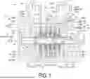


Sources:
- United States Patent and Trademark Office - verify current appl. status at the USPTO↗
Similar patent applications:
- » 20240262056
COMPRESSOR SYSTEM FOR A PUNCTURE REPAIR KIT, PUNCTURE REPAIR KIT HAVING SUCH A COMPRESSOR SYSTEM, AND METHOD FOR SEALING A VEHICLE TYRE WITH SUCH A COMPRESSOR SYSTEM - » 20220146168
Refrigeration systems with a first compressor system and a second compressor system - » 20240310099
Refrigeration Systems with a First Compressor System and a Second Compressor System - » 20220205696
Refrigeration systems with a first compressor system and a second compressor system - » 20200064037
Refrigeration systems with a first compressor system and a second compressor system - » 20250290513
LIQUID SEPARATION DEVICE FOR A COMPRESSOR SYSTEM AND COMPRESSOR SYSTEM HAVING SUCH A LIQUID SEPARATION DEVICE - » 20200362862
Intake pipe used for compressor system and compressor system - » 20200378395
METHOD AND SYSTEM FOR IDENTIFYING A FAILURE IN A COOLING SYSTEM COMPRESSOR AND COOLING SYSTEM COMPRESSOR - » 20210046409
Coalescence separator, in particular for use in a compressed air compressor system, compressed air compressor system, and use of a coalescence separator - » 20210054836
Method for actuating a compressor system and a compressor system
Recent applications in this class:
- » 20260022705 2026-01-22
ROTATION DEVICE AND METHOD FOR DETERMINATION OF A CONDITION OF A BEARING ARRANGEMENT - » 20260002544 2026-01-01
METHOD FOR SELECTING BOOSTER PUMP FOR CIRCUITING COOLING WATER OF BYPASS PIPING SYSTEM - » 20250347285 2025-11-13
FAN MONITORING METHOD, SYSTEM, AND APPARATUS, SERVER, AND READABLE STORAGE MEDIUM - » 20250283475 2025-09-11
CONNECTED VACUUM SYSTEM WITH SENSOR SUITE - » 20250264109 2025-08-21
SYSTEM AND METHOD FOR DETECTING A PERFORMANCE DEGRADATION OF A BLEED-OFF VALVE - » 20250257735 2025-08-14
FAN FAULT DETECTION METHOD AND APPARATUS, COMPUTER DEVICE, AND STORAGE MEDIUM - » 20250237227 2025-07-24
SYSTEM AND METHOD FOR MONITORING PUMP VIBRATIONS - » 20250215884 2025-07-03
METHOD FOR OPERATING A POWER GENERATION DEVICE HAVING A CHARGE AIR COMPRESSOR, CONTROL DEVICE FOR CARRYING OUT SUCH A METHOD, AND POWER GENERATION DEVICE HAVING SUCH A CONTROL DEVICE - » 20250198418 2025-06-19
ELECTRONIC DEVICE FOR PREDICTING OCCURRENCE OF AIR LEAKAGE OF AIR COMPRESSOR AND METHOD OF OPERATING THE SAME - » 20250163924 2025-05-22
TURBOMOLECULAR VACUUM PUMP AND ASSOCIATED METHOD
Recent applications for this Assignee:
- » 20250271341 2025-08-28
LOCAL PRESSURE TESTING JIG AND LOCAL PRESSURE TESTING METHOD - » 20250270936 2025-08-28
INLET GUIDE VANE AND ROTARY MACHINE - » 20250269478 2025-08-28
SEAL REMOVAL JIG, SEAL REMOVAL METHOD, AND SEAL PORTION - » 20250243874 2025-07-31
CENTRIFUGAL COMPRESSOR - » 20250137390 2025-05-01
COMPRESSOR TRAIN FOR CHEMICAL PLANT - » 20170254785 2017-09-07
Ultrasonic flaw-detection method and apparatus for blade groove in turbine rotor disc - » 20170254344 2017-09-07
Centrifugal compressor