TORQUE AMPLIFIER FOR DAMPER
US20260036331A1
2026-02-05
19/286,889
2025-07-31
Smart Summary: A new system helps improve how dampers work. It includes an actuator, which is a device that creates movement, and a torque amplifier that boosts the strength of that movement. The actuator has a protective case and a part called an output shaft. The torque amplifier sits outside the actuator and connects to both the output shaft and the damper's driving shaft. Its main job is to increase the power from the actuator and send that stronger power to the damper. 🚀 TL;DR
Abstract:
A damper driving arrangement is disclosed. The arrangement includes an actuator and a torque amplifier. The actuator has a housing for enclosing components of the actuator and an output shaft. The torque amplifier is positioned outside the housing and coupled to the output shaft of the actuator and a driving shaft of a damper. The torque amplifier is configured to amplify torque received from the actuator and transfer amplified torque to the damper.
Inventors:
- Ujjain Kumar Bidila 6 🇮🇳 Hyderabad, India
- Jeffrey Scott Beneke 11 🇺🇸 Peculiar, MO, United States
- Digambar Satappa Killedar 3 🇮🇳 Pune, India
Applicant:
Interested in similar patents?
Get notified when new applications in this technology area are published.
Classification:
F24F13/1426 » CPC main
Details common to, or for air-conditioning, air-humidification, ventilation or use of air currents for screening; Air-flow control members, e.g. louvres, grilles, flaps or guide plates movable, e.g. dampers built up of tilting members, e.g. louvre characterised by actuating means
F24F2013/1446 » CPC further
Details common to, or for air-conditioning, air-humidification, ventilation or use of air currents for screening; Air-flow control members, e.g. louvres, grilles, flaps or guide plates movable, e.g. dampers built up of tilting members, e.g. louvre characterised by actuating means with gearings
F24F13/14 IPC
Details common to, or for air-conditioning, air-humidification, ventilation or use of air currents for screening; Air-flow control members, e.g. louvres, grilles, flaps or guide plates movable, e.g. dampers built up of tilting members, e.g. louvre
Description
CROSS-REFERENCE TO RELATED APPLICATIONS
The present application claims priority to Indian Provisional Patent Application No. 202411058131, filed Jul. 31, 2025, the entire contents of which is incorporated by reference herein.
BACKGROUND
The present disclosure relates generally to dampers for HVAC systems.
Generally, dampers are positioned within and/or form a portion of the ductwork and are used to regulate fluid flow along the ductwork. For example, the dampers may control conditioned air flow supplied to various rooms, zones, or other spaces within the building during operation of the HVAC system. The dampers can transition to a closed configuration to block fluid flow along the ductwork in response to a temperature within or near the ductwork exceeding a threshold value.
SUMMARY
The present disclosure provides, in one aspect, a damper driving arrangement including an actuator having an output shaft, and a torque amplifier coupled to the output shaft of the actuator and a driving shaft of a damper. The torque amplifier is configured to amplify torque received from the actuator, and transfer amplified torque to the damper.
In some embodiments, the torque amplifier includes one or more gear trains to amplify the torque received from the actuator.
In some embodiments, the driving shaft is a jackshaft or an extended shaft of the damper.
In some embodiments, the torque amplifier is coupled to the output shaft of the actuator via a coupler shaft arrangement.
The present disclosure provides, in another aspect, a damper driving mechanism including an actuator having a housing and an output shaft, and a torque amplifier positioned between the actuator and the damper, where the torque amplifier is coupled to the output shaft of the actuator and a driving shaft of a damper, and where the torque amplifier includes a gear train configured to amplify torque received from the actuator and transfer amplified torque to the damper.
The present disclosure provides, in yet another aspect, a damper assembly for an HVAC system including a damper plate having a driving shaft configured to adjust the position of the damper plate, an actuator having a housing and an output shaft, and a torque amplifier coupled to the output shaft of the actuator and the driving shaft of a damper, the torque amplifier configured to amplify torque received from the actuator and transfer amplified torque to the damper.
According to another aspect, the arrangement includes an actuator and a torque amplifier. The actuator has a housing and an output shaft. The torque amplifier is positioned outside the housing, and coupled to the output shaft of the actuator and a driving shaft of a damper. The torque amplifier is configured to amplify torque received from the actuator, and transfer amplified torque to the damper.
BRIEF DESCRIPTION OF THE DRAWINGS
Various objects, aspects, features, and advantages of the disclosure will become more apparent and better understood by referring to the detailed description taken in conjunction with the accompanying drawings, in which like reference characters identify corresponding elements throughout. In the drawings, like reference numbers generally indicate identical, functionally similar, and/or structurally similar elements.
FIG. 1 is a perspective view of an embodiment of a building that may utilize a heating, ventilation, and/or air conditioning (HVAC) system, in accordance with an aspect of the present disclosure.
FIG. 2 is a schematic view depicting a damper driving arrangement, according to some embodiment of the present disclosure.
FIG. 3 is another schematic view depicting the arrangement.
FIG. 4B is a schematic view depicting an interior of a torque amplifier of the arrangement from a side view, according to some embodiments.
FIG. 4B is a schematic view depicting an interior of a torque amplifier of the arrangement from a top view, according to some embodiments.
FIG. 5 is a schematic view of the torque amplifier of the arrangement, according to some embodiments.
DETAILED DESCRIPTION
One or more specific embodiments of the present disclosure will be described below. These described embodiments are only examples of the presently disclosed techniques. Additionally, in an effort to provide a concise description of these embodiments, all features of an actual implementation may not be described in the specification. It should be appreciated that in the development of any such actual implementation, as in any engineering or design project, numerous implementation-specific decisions must be made to achieve the developers' specific goals, such as compliance with system-related and business-related constraints, which may vary from one implementation to another. Moreover, it should be appreciated that such a development effort might be complex and time consuming, but may nevertheless be a routine undertaking of design, fabrication, and manufacture for those of ordinary skill having the benefit of this disclosure.
When introducing elements of various embodiments of the present disclosure, the articles “a,” “an,” and “the” are intended to mean that there are one or more of the elements. The terms “comprising,” “including,” and “having” are intended to be inclusive and mean that there may be additional elements other than the listed elements. Additionally, it should be understood that references to “one embodiment” or “an embodiment” of the present disclosure are not intended to be interpreted as excluding the existence of additional embodiments that also incorporate the recited features.
Building HVAC System
As briefly discussed above, a heating, ventilation, and/or air conditioning (HVAC) system may be used to thermally regulate a space within a building, home, or other suitable structure. The HVAC system may include an HVAC unit configured to condition an air flow via an evaporator, a furnace, a heating coil, a chiller system, other components, or a combination thereof, and to provide the conditioned air flow (e.g., a heated air flow, a cooled air flow, a dehumidified air flow) to the space. For example, the HVAC unit may be fluidly coupled to the space via an air distribution system, such as a system of ductwork, which extends between the HVAC unit and the space. As such, one or more fans or blowers of the HVAC system may be operable to direct a supply of conditioned air from the HVAC unit, through the ductwork, and into the spaces within the building.
Typically, the HVAC system includes one or more dampers that are disposed within the ductwork and are configured to regulate fluid flow along the ductwork. For example, the dampers may include adjustable dampers that are set to particular positions (e.g., manually, via an actuator of the dampers) to achieve a desired flow rate of conditioned air to the room, zone, or other space serviced by the dampers. In some embodiments, the dampers can include fire dampers that are configured to transition to a closed configuration to block fluid flow (e.g., air, smoke) along the ductwork in response to a temperature within or near the ductwork exceeding or approaching a threshold value.
Turning now to the drawings, FIG. 1 illustrates an embodiment of a heating, ventilation, and/or air conditioning (HVAC) system for environmental management that may employ one or more HVAC units. As used herein, an HVAC system includes any number of components configured to enable regulation of parameters related to climate characteristics, such as temperature, humidity, air flow, pressure, air quality, and so forth. For example, an “HVAC system” as used herein is defined as conventionally understood and as further described herein. Components or parts of an “HVAC system” may include, but are not limited to, all, some of, or individual parts such as a heat exchanger, a heater, an air flow control device, such as a fan, a sensor configured to detect a climate characteristic or operating parameter, a filter, a control device configured to regulate operation of an HVAC system component, a component configured to enable regulation of climate characteristics, or a combination thereof. An “HVAC system” is a system configured to provide such functions as heating, cooling, ventilation, dehumidification, pressurization, refrigeration, filtration, or any combination thereof. The embodiments described herein may be utilized in a variety of applications to control climate characteristics, such as residential, commercial, industrial, transportation, or other applications where climate control is desired.
In the illustrated embodiment, a building 10 is air conditioned by an HVAC system 11 having an HVAC unit 12. The building 10 may be a commercial structure or a residential structure. As shown, the HVAC unit 12 is disposed on the roof of the building 10; however, the HVAC unit 12 may be located in other equipment rooms or areas adjacent the building 10. The HVAC unit 12 may be a single package unit containing other equipment, such as a blower, integrated air handler, and/or auxiliary heating unit. In other embodiments, the HVAC unit 12 may be part of a split HVAC system, which includes an outdoor HVAC unit and an indoor HVAC unit.
The HVAC unit 12 is an air-cooled device that implements a refrigeration cycle to provide conditioned air to the building 10. Specifically, the HVAC unit 12 may include one or more heat exchangers across which an air flow is passed to condition the air flow before the air flow is supplied to the building 10. In the illustrated embodiment, the HVAC unit 12 is a rooftop unit (RTU) that conditions a supply air stream, such as environmental air and/or a return air flow from the building 10. The HVAC unit 12 may provide a variety of heating and/or cooling functions, such as cooling only, heating only, cooling with electric heat, cooling with dehumidification, cooling with gas heat, or cooling with a heat pump. For example, in certain embodiments, the HVAC unit 12 may be a heat pump that provides both heating and cooling to the building with one refrigeration circuit configured to operate in different modes. In other embodiments, the HVAC unit 12 may include one or more refrigeration circuits for cooling an air stream and a furnace for heating the air stream.
In any case, after the HVAC unit 12 conditions the air, the air may be supplied to the building 10 via ductwork 14 extending from the HVAC unit 12 and throughout the building 10. For example, the ductwork 14 may extend to various individual floors, rooms zones, or other sections or spaces of the building 10. In some embodiments, a plurality of diffuser assemblies 16 are coupled to the ductwork 14. The diffuser assemblies 16 may direct the conditioned air received from the ductwork 14 into the various spaces of the building 10 in a manner that improves air distribution and/or air dispersion across the spaces.
In some embodiments, a control device 18, one type of which may be a thermostat, may be used to designate the temperature of the conditioned air supplied by the HVAC unit 12. The control device 18 also may be used to control the flow of air through the ductwork 14. For example, the control device 18 may be used to regulate operation of one or more components of the HVAC unit 12 or other components, such as dampers and fans, within the building 10 that may control flow of air through and/or from the ductwork 14. In some embodiments, other devices may be included in the system, such as pressure and/or temperature transducers or switches that sense the temperatures and pressures of supply air, return air, and so forth. Moreover, the control device 18 may include computer systems that are integrated with or separate from other building control or monitoring systems, and even systems that are remote from the building 10.
In the illustrated embodiment, the HVAC system 11 includes a plurality of damper assemblies 20 (e.g., dampers) that are coupled to the ductwork 14 and/or form a portion of the ductwork 14 and are configured to regulate fluid flow through the ductwork 14. For example, the damper assemblies 20 may include one or more dampers configured to regulate distribution of a flow of conditioned air generated by the HVAC unit 12 to one or more rooms, zones, or other spaces within the building 10.
Torque Amplifier for Damper
An actuator is provided with a damper for controlling operation of the damper. For example, the actuator is coupled to a jackshaft of the damper to rotate it resulting in rotation of blades of the damper. The actuator rotates the jackshaft to either open the damper or close the damper. The actuator may position the damper in partially open state. Cost of the actuator increases with increase in output torque capacity of the actuator. When the torque requirement of the damper is on higher side, a costly actuator is required to operate the damper. In some scenarios, more than one actuator is implemented to fulfill torque requirement of a damper.
The present disclosure discloses a driving arrangement having a torque amplifier to amplify torque of the actuator. The torque amplifier is coupled to the output shaft of the actuator and a driving shaft of a damper. The torque amplifier is configured to amplify torque received from the actuator, and transfer amplified torque to the damper.
The torque amplifier may include one or more gear trains receiving torque from the actuator, amplifying the torque to deliver to the damper.
The driving arrangement (hereinafter also referred as arrangement) of the present disclosure is now described in detail with reference to accompanying FIGS. 2 to 5.
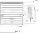
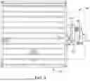
FIG. 2 is a schematic view depicting a damper driving arrangement 100 according to some embodiment of the present disclosure. FIG. 3 is another schematic view depicting the arrangement 100. Referring to FIG. 2 and FIG. 3, the arrangement 100 includes an actuator 110 and a torque amplifier 120. The actuator 110 has a housing 140 for enclosing components of the actuator 110. The components may include electrical and mechanical components of the actuator 110. The actuator 110 has an output shaft 150 for delivering the torque. In some embodiments, the output shaft 150 may protrude out of the housing 140.
The torque amplifier 120 is coupled to the output shaft 150 of the actuator 110 and a driving shaft of a damper 160. The torque amplifier 120 is positioned outside the housing 140. More specifically, the torque amplifier 120 is a separate device attachable to the actuator 110. In the illustrated embodiment, the torque amplifier 120 is positioned between the actuator 110 and the damper 160 in order to be able to receive an initial force from the actuator 110, amplify the force, and then transfer the amplified force to the damper 160.
The torque amplifier 120 can be coupled to the output shaft 150 of the actuator 110 via any suitable connecting means. In some embodiments, the torque amplifier 120 is coupled to the output shaft 150 via a coupler shaft arrangement. Further, the torque amplifier 120 may be coupled to a jackshaft or an extended shaft of the damper 160.
The arrangement 100 may further include a connector assembly 170 for supporting the actuator 110 and the torque amplifier 120. The connector assembly 170 may be suitably connected to a frame of the damper 160. In some other embodiments, the connector assembly 170 may be attached to any other suitable support.
The torque amplifier 120 is configured to amplify torque received from the actuator 110 and transfer amplified torque to the damper 160. The torque amplifier 120 may be configured based on torque requirement of the damper 160 and torque output capacity of the actuator 110. The torque amplifier 120 may include suitable components to amplify the torque. In one example, the torque amplifier 120 may include one or more gear trains to amplify torque received from the actuator 110.
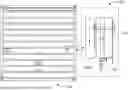
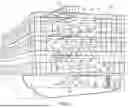
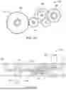
FIGS. 4A and 4B is a schematic view depicting an interior of the torque amplifier 120, according to some embodiments. Referring to FIG. 4A, the torque amplifier 120 includes a first plate 180 and a second plate 185 arranged spaced apart from the first plate 180. The torque amplifier 120 includes an input spindle 190 supported by the first plate 180 and a second plate 185. Suitable bushings (for example, flange bushing) may be provided between the input spindle 190 and the plates 180, 185 to facilitate rotation of the input spindle 190. The input spindle 190 is configured to be attachable to the output shaft 150 of the actuator 110. The torque amplifier 120 further includes an output spindle 200 arranged spaced apart from the input spindle 190, and supported by the plates 180, 185 via bushings, like flange bushing. The output spindle 200 is configured to be attached to the driving shaft of the damper 160. For example, the output spindle 200 is configured to be attached to the jackshaft or the extended shaft of the damper 160.
The torque amplifier 120 includes a gear train 210 coupled to the input spindle 190 and the output spindle 200. The gear train 210 includes a plurality of gears 220 supported via gear supports 230. Appropriate bushes may be provided on the gear supports 230. Configuration of the gears 220 (for example, number of teeth, type, and size of the gears) may be determined based on torque amplification requirement. In an operative configuration, the input spindle 190 receives torque from the actuator 110. The gear train 210 amplifies the torque and amplified torque is delivered to the damper 160 via the output spindle 200.
In some embodiments, the input spindle 190 and the output spindle 200 may be provided with retainer locks for gears mounted on the input spindle 190 and the output spindle 200.
Configuration of the gear train 210 is determined based on the desired torque requirement. The gear train 210 is so configured that it amplifies the torque received from the actuator 110 to match output torque of the torque amplifier 120 with torque requirement of the damper 160. This eliminates need of more than one actuator or costly actuator. In some embodiments, the torque amplifier 120 is able to amplify the torque provided by the actuator 110 by 50% or more. In some embodiments, the torque amplifier 120 is able to double the amount of torque provided by the actuator prior to being transferred to the damper 160.
Alternatively, or additionally, the torque amplifier 120 may include other suitable means (for example, belt and pulley arrangement) to amplify torque output of the actuator 110.
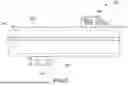
FIG. 5 is a schematic view of the torque amplifier 120 of the arrangement, according to some embodiments. The torque amplifier 120 may include an enclosure 240 for enclosing components (for example, the input spindle 190, the output spindle 200, the gear train 210, etc.) of the torque amplifier 120. The enclosure 240 may formed by joining a first part 250 and a second part 260 together. The torque amplifier 120 may include a shaft coupler 270 for coupling the input spindle 190 to the output shaft 150 of the actuator 110. In some embodiments, the input spindle 190 and the output spindle 200 are arranged on opposite surfaces of the enclosure 240 and are non-coaxial.
CONFIGURATION OF EXEMPLARY EMBODIMENTS
The construction and arrangement of the systems and methods as shown in the various exemplary embodiments are illustrative only. Although only a few embodiments have been described in detail in this disclosure, many modifications are possible (e.g., variations in sizes, dimensions, structures, shapes and proportions of the various elements, values of parameters, mounting arrangements, use of materials, colors, orientations, etc.). For example, the position of elements can be reversed or otherwise varied and the nature or number of discrete elements or positions can be altered or varied. Accordingly, all such modifications are intended to be included within the scope of the present disclosure. The order or sequence of any process or method steps can be varied or re-sequenced according to alternative embodiments. Other substitutions, modifications, changes, and omissions can be made in the design, operating conditions and arrangement of the exemplary embodiments without departing from the scope of the present disclosure.
Although the figures show a specific order of method steps, the order of the steps may differ from what is depicted. Also, two or more steps can be performed concurrently or with partial concurrence. Such variation will depend on the software and hardware systems chosen and on designer choice. All such variations are within the scope of the disclosure. Likewise, software implementations could be accomplished with standard programming techniques with rule-based logic and other logic to accomplish the various connection steps, processing steps, comparison steps and decision steps.
Claims
What is claimed is:1. A damper driving mechanism, comprising:
an actuator having an output shaft; and
a torque amplifier coupled to the output shaft of the actuator and a driving shaft of a damper, the torque amplifier configured to amplify torque received from the actuator and transfer amplified torque to the damper.
2. The damper driving arrangement of claim 1, wherein the torque amplifier includes one or more gear trains to amplify the torque received from the actuator.
3. The damper driving arrangement of claim 1, wherein the driving shaft is a jackshaft or an extended shaft of the damper.
4. The damper driving arrangement of claim 1, wherein the torque amplifier is a separate device that is attachable to the actuator.
5. The damper driving arrangement of claim 4, further comprising a connector assembly extending between the actuator and the torque amplifier to couple the torque amplifier to the actuator.
6. The damper driving arrangement of claim 1, wherein the torque amplifier includes an input spindle coupled to the actuator and an output spindle coupled to the drive shaft of the damper.
7. The damper driving arrangement of claim 6, wherein the input spindle and the output spindle are spaced apart and are non-coaxial.
8. The damper driving arrangement of claim 7, wherein a gear train extends between the input spindle and the output spindle.
9. The damper driving arrangement of claim 1, wherein the amplifier increases the torque provided by the actuator by at least 50%.
10. The damper driving arrangement of claim 1, wherein the amplifier doubles the torque provided by the actuator.
11. A damper driving mechanism, comprising:
an actuator having a housing and an output shaft; and
a torque amplifier positioned between the actuator and the damper; the torque amplifier coupled to the output shaft of the actuator and a driving shaft of a damper, the torque amplifier including a gear train configured to amplify torque received from the actuator and transfer amplified torque to the damper.
12. The damper driving arrangement of claim 11, wherein the torque amplifier includes an input spindle coupled to the actuator and an output spindle coupled to the drive shaft of the damper.
13. The damper driving arrangement of claim 12, wherein the input spindle and the output spindle are spaced apart and are non-coaxial.
14. The damper driving arrangement of claim 11, wherein the amplifier increases the torque provided by the actuator by at least 50%.
15. The damper driving arrangement of claim 11, wherein the torque amplifier is positioned between the actuator and the damper, and wherein a connector assembly supports the torque amplifier and the actuator adjacent to the damper.
16. A damper assembly for an HVAC system, comprising:
a damper plate having a driving shaft configured to adjust the position of the damper plate;
an actuator having a housing and an output shaft; and
a torque amplifier coupled to the output shaft of the actuator and the driving shaft of a damper, the torque amplifier configured to amplify torque received from the actuator and transfer amplified torque to the damper.
17. The damper driving arrangement of claim 16, wherein the torque amplifier includes an input spindle coupled to the actuator and an output spindle coupled to the drive shaft of the damper.
18. The damper driving arrangement of claim 17, wherein the input spindle and the output spindle are spaced apart and are non-coaxial.
19. The damper driving arrangement of claim 16, wherein the amplifier increases the torque provided by the actuator by at least 50%.
20. The damper driving arrangement of claim 16, wherein the torque amplifier is positioned between the actuator and the damper, and wherein a connector assembly supports the torque amplifier and the actuator adjacent to the damper.
Images & Drawings included:
Sources:
- United States Patent and Trademark Office - verify current appl. status at the USPTO↗
Recent applications in this class:
- » 20260036330 2026-02-05
DAMPER ASSEMBLY-CONTAINING CONNECTOR AND METHOD OF USE - » 20260009557 2026-01-08
STANDOFF FOR DUCTWORK DAMPER ASSEMBLY, DUCTWORK DAMPER ASSEMBLY INCORPORATING SAME AND METHOD OF ASSEMBLING DUCTWORK DAMPER ASSEMBLY - » 20250347440 2025-11-13
BACKDRAFT DAMPER WITH ELECTROMAGNET FOR TERMINAL UNIT - » 20250251169 2025-08-07
SHUTTER DEVICE AND VENTILATION DEVICE - » 20250060126 2025-02-20
ACTUATOR WITH MODULAR FAIL-SAFE ASSEMBLY - » 20240418399 2024-12-19
AIR HANDLING DEVICE - » 20240328666 2024-10-03
Apparatus for stabilizing blade for relief damper - » 20240328665 2024-10-03
DAMPER DOOR FOR AN AIR CONDITIONING APPLIANCE - » 20240280289 2024-08-22
DAMPER FOR HVAC SYSTEM - » 20240183571 2024-06-06
CONDENSER FAN ROTATION RESTRICTION SYSTEM