ROTOR
US20260036375A1
2026-02-05
19/099,828
2023-09-14
Smart Summary: A rotary heat pump uses a rotating axis to move a gas, which helps increase its pressure. This gas travels through special ducts that guide it away from and towards the center, allowing it to expand and contract. Heat is transferred between the gas and a liquid through separate ducts, helping to manage temperature. The design includes multiple rotor plates that contain these ducts and are connected together. Overall, this system efficiently moves and heats a working medium to provide heating or cooling. 🚀 TL;DR
Abstract:
Rotor, in particular a rotary heat pump, including a rotational axis, a number of compression ducts in which a working medium, in particular a gas, preferably a noble gas, is guided away from the rotational axis to increase the pressure due to the centrifugal acceleration, a number of expansion ducts in which the working medium is guided towards the rotational axis to reduce the pressure due to the centrifugal acceleration, a number of first heat transfer ducts for the working medium and a number of second heat transfer ducts for a heat transfer medium, in particular a liquid, so that heat is transferred between the working medium flowing in the first heat transfer ducts and the heat transfer medium flowing in the second heat transfer ducts, a number of first (10) and second rotor plates including the compression ducts, the expansion ducts, the first heat transfer ducts for the working medium and the second heat transfer ducts for the heat transfer medium, wherein the first and second rotor plates are connected to each other along their main planes of extension.
Inventors:
- Bernhard Adler 5 🇦🇹 Gramatneusiedl, Austria
- Johannes Erhard 3 🇦🇹 Graz, Austria
- Andreas LÄNGAUER 2 🇦🇹 Wien, Austria
- Christian RAKUSCH 2 🇦🇹 Pressbaum, Austria
Applicant:
Interested in similar patents?
Get notified when new applications in this technology area are published.
Classification:
F28D2021/0019 » CPC further
Heat-exchange apparatus not covered by any of the groups - Other heat exchangers for particular applications; Heat exchange systems not otherwise provided for
F28F2255/00 » CPC further
Heat exchanger elements made of materials having special features or resulting from particular manufacturing processes
F28D11/02 » CPC main
Heat-exchange apparatus employing moving conduits the movement being rotary, e.g. performed by a drum or roller
F28D21/00 IPC
Heat-exchange apparatus not covered by any of the groups -
Description
The invention relates to a rotor, in particular a rotary heat pump, comprising:
-
- a rotational axis,
- a number of compression ducts in which a working medium, in particular a gas, preferably a noble gas, is guided away from the rotational axis to increase the pressure due to the centrifugal force,
- a number of expansion ducts in which the working medium is guided towards the rotational axis to reduce the pressure due to the centrifugal force,
- a number of first heat transfer ducts for the working medium and
- a number of second heat transfer ducts for a heat transfer medium, in particular a liquid, so that heat is transferred between the working medium flowing in the first heat transfer ducts and the heat transfer medium flowing in the second heat transfer ducts.
A rotary heat pump is known from WO 2015/103656, in which the centrifugal acceleration of the rotor is used to generate different pressure and temperature levels. Heat at a high temperature is extracted from the compressed working medium and heat at a comparatively low temperature is supplied to the expanded working medium. For this purpose, the rotary heat pump comprises internal heat exchangers and external heat exchangers, which are essentially arranged parallel to the axis of rotation of the rotor. The inner heat exchangers are set up for heat exchange at a lower temperature and the outer heat exchangers for heat exchange at a higher temperature. This type of rotary heat pump has significant advantages over stationary heat pumps. A disadvantage, however, is the high construction complexity of the known rotary heat pump. In addition, there is a need for improvement with regard to rotor dynamics, which in the state of the art is impaired by the mechanical connection of the individual components. Finally, there are always efforts to further increase the efficiency of such rotary heat pumps (COP—Coefficient of Performance).
The present invention thus sets itself the object of mitigating or eliminating at least some of the disadvantages of the prior art. The preferred aim of the invention is to create a rotor which combines low construction effort with high efficiency.
This object is solved by a rotor according to claim 1 and a method according to claim 13. Preferred embodiments are given in the dependent claims.
According to the invention, a number of first and second rotor plates are provided, wherein the first and/or the second rotor plates comprise the compression ducts, the expansion ducts, the first heat transfer ducts for the working medium and the second heat transfer ducts for the heat transfer medium, wherein the first and the second rotor plates are connected to each other along their main planes of extension.
The arrangement of the first and second rotor plates forms a compact rotor element that is particularly stable against rotational forces and combines the functions that are separated into individual components such as inner and outer heat exchangers and expansion and compression ducts in the prior art. To form the rotor element, the first and second rotor plates are stacked in contact with each other and connected to each other at their meeting main planes of extension. In the first and/or second rotor plates, the working medium flows through flow ducts, which form the first heat transfer ducts, the compression ducts and the expansion ducts. Accordingly, the heat transfer medium flows through the second heat transfer ducts of the first and/or second rotor plates to enable heat transfer with the working medium. So-called “micro channel diffusion bonded heat exchangers” were already known in the prior art, cf. e.g. EP 3 885 691 A1, in which a stack of heat exchanger plates with integrated flow passages are connected to one another by diffusion connections (diffusion bonds). However, the invention not only replaces the inner and outer heat exchangers of known rotary heat pumps with this type of heat exchanger, but also integrates the expansion and compression ducts into the first and second rotor plates of the rotor element. Thus, not only the heat transfer between the working medium and the heat transfer medium, but also the compression of the working medium when flowing away from the rotational axis and the expansion of the working medium when flowing towards the rotational axis are carried out in the flow ducts of the rotor element. This makes it possible to create a rotor, in particular a rotary heat pump or a heat engine for providing electric current from a heat flow, in which the essential process steps are integrated into the interior of the package of the first and second rotor plates. This construction achieves particularly favorable rotor dynamics. In particular, it has proven to be advantageous that the first and second rotor plates can virtually not move against each other, so that the number of balancing runs can be significantly reduced or balancing runs can be avoided altogether. Furthermore, the rotor element consisting of the first and second rotor elements can be realized in different designs, in particular also with smaller dimensions. This has the advantage that production can be simplified and a less powerful drive unit can be used. Compared to the discrete heat exchangers of the prior art, the available heat exchanger surfaces can also be increased during operation of the rotor. The integral design of the rotor element also means that the number of sealing points can be significantly reduced.
For the purposes of this disclosure, the indications of location and direction refer to the intended state of use of the rotor, where “radial”, “axial” and “in circumferential direction” refer to the rotational axis. In relation to the flow of the working or heat transfer medium, “inside” means closer to the rotational axis of the rotor and “outside” means further away from the rotational axis.
In a preferred embodiment, the main planes of extension of the first and second rotor plates, i.e. their plate planes in which the first and second rotor plates each have their greatest extension, are each arranged essentially perpendicular to the rotational axis. Preferably, the rotational axis passes through the centers of each of the first and second rotational axes. Furthermore, it is favorable if the first and second rotor plates are arranged essentially congruently when viewed in the direction of the rotational axis.
In a preferred embodiment, the first rotor plates each comprise at least one of the compression ducts, at least one of the expansion ducts and at least one of the first heat transfer ducts for the working medium and the number of second rotor plates each comprise at least one of the second heat transfer ducts for the heat transfer medium.
In a preferred embodiment, the first rotor plates each comprise at least one flow duct for the working medium, wherein the at least one flow duct comprises an inlet opening for the working medium at a first end and an outlet opening for the working medium at a second end. In a preferred embodiment, the flow duct comprises a flow duct section, preferably running essentially radially outwards, to form one of the compression ducts and/or a flow duct section, preferably running essentially radially inwards, to form one of the expansion ducts and/or a flow duct section, preferably running essentially in the circumferential direction, to form one of the first heat transfer ducts. The working medium can thus be distributed to the flow ducts within the first rotor plates via the inlet openings. The working medium then flows along the flow ducts to the outlet openings, at which the working medium is led out of the rotor element. In the flow duct section leading outwards, the working medium can be compressed by the effect of centrifugal acceleration when the rotor is rotating. In the flow duct section leading inwards, the working medium can be expanded, also due to the centrifugal force. Heat can be transferred between the working medium and the heat transfer medium in the flow channel cross-section, which essentially runs in the circumferential direction. The individual flow duct sections are connected so that the working medium can flow through the flow duct within the first rotor plate from the inlet opening to the outlet opening.
In a preferred embodiment, the inlet openings and/or the outlet openings of the first rotor plates are each arranged in alignment, i.e. in a line parallel to the rotational axis. Preferably, the inlet openings and/or the outlet openings are each congruent when viewed in a direction parallel to the rotational axis.
In order to enable the working medium to pass through the second rotor plates, the second rotor plates in this embodiment preferably comprise pass-through openings arranged in alignment with the inlet openings or in alignment with the outlet openings. In this way, the working medium can be supplied on one side of the rotor element and distributed to the first rotor plates via the inlet openings, with second rotor plates arranged in between being passed through via the pass-through openings.
In order to keep the number of connections as low as possible, in a preferred embodiment the outlet openings are arranged in central areas of the first rotor plates through which the rotational axis passes. Preferably, the rotational axis passes through the centers of the outlet openings. The working medium can be guided along the flow ducts to the outlet openings in the central areas of the first rotor plates and discharged from the first rotor plates via the outlet openings, which are preferably arranged in alignment. Advantageously, several flow ducts of the first rotor plates can share the same outlet opening in the central area.
A fan is preferably provided to maintain the flow of the working medium. The fan is preferably arranged in the axial direction outside the rotor element consisting of the first and second rotor plates. The fan can be used to create a circular flow of the working medium from the fan via the inlet openings through the flow ducts inside the rotor element, via the outlet openings back to the fan and finally back to the inlet openings in the flow ducts inside the rotor element. This allows the working medium to run through a circular process.
Depending on the arrangement of the flow ducts in the first rotor plates, different types of circular processes can be achieved, for example a Joule process with essentially isobaric heat transfer.
Depending on the embodiment, the fan can be connected to a fan drive, with which a blade wheel of the fan can be set in rotation. The fan drive can be used to rotate the blade wheel relative to the rotor element, which is preferably set in rotation by a motor that is different from the fan drive.
To achieve the circular flow of the working medium, the inlet openings of the first rotor plates can be connected to an outlet of the fan and/or the outlet openings of the first rotor plates can be connected to an inlet of the fan.
In order to improve the heat transfer between the working medium and the heat transfer medium, in a preferred embodiment the first rotor plates each comprise several flow ducts, each with at least one flow duct section that preferably extends essentially radially outwards and/or with at least one flow duct section that preferably extends essentially radially inwards and/or with at least one flow duct section that preferably extends essentially in the circumferential direction. Thus, several flow ducts can be formed on the first rotor plates, through which the working medium can flow in parallel. The flow ducts can be distributed over the surface of the first rotor plates. Preferably, more than three, in particular more than six, for example twelve, flow ducts are provided at different angular positions per first rotor plate.
In a preferred embodiment, the flow ducts of the first rotor plates each comprise several flow duct sections, preferably running essentially in the circumferential direction, at different radial distances from the rotational axis to form several first heat transfer ducts. The flow duct sections running in the circumferential direction are preferably arranged in loops. Preferably, several inner, for example S-shaped, loops for heat exchange with the heat transfer medium in inner loops of one of the second heat transfer ducts of one of the second rotor plates are provided and/or several outer, for example S-shaped, loops for heat exchange with the heat transfer medium are provided in outer loops of one of the second heat transfer ducts of one of the second rotor plates are provided. In this embodiment, intermediate compression or expansion can be achieved during the heat exchange with the heat transfer medium. This allows the temperature to be raised again after a heat transfer in order to either transfer the heat at an essentially constant temperature or to increase efficiency if an application with a small temperature difference between the inlet and outlet of the heat transfer medium is intended.
In order to reduce the necessary connections for the working medium, in a preferred embodiment two adjacent flow ducts of the first rotor plates are arranged mirrored with respect to a plane of symmetry spanned in the axial and radial direction, with the two adjacent flow ducts sharing a common inlet opening and a common outlet opening for the working medium. If, for example, 12 flow ducts are provided at different angular positions per first rotor plate, only six connections are required for the inlet of the working medium in this embodiment.
In a preferred embodiment, the second rotor plates each comprise at least one inner flow duct and at least one outer flow duct for forming one of the second heat transfer ducts, with the outer flow duct being arranged further outwards in the radial direction than the inner flow duct. When used as a rotary heat pump, the outer flow duct can be designed as an outer heat exchanger in which the heat transfer medium, in this case the sink medium, absorbs heat from the working medium. The inner flow duct can be designed as an inner heat exchanger in which the heat transfer medium, in this case the source medium, transfers heat to the working medium. Alternatively, the rotor can be designed as a heat engine.
In a further embodiment, the first rotor plates comprise the second heat transfer ducts for the heat transfer medium. In this embodiment, the second rotor plates can be formed as separating plates for the first rotor plates, whereby the second separating plates are preferably free of flow ducts for both the working medium and the heat transfer medium.
For the integral formation of the individual flow ducts, it is favorable if the compression ducts, the expansion ducts and the first heat transfer ducts for the working medium are formed as indentations starting from preferably essentially flat first outer surfaces of the first rotor plates, whereby the second heat transfer ducts for the heat transfer medium are formed
-
- i. as indentations starting from preferably essentially flat outer surfaces of the second rotor plates or
- ii. as indentations starting from preferably essentially flat second outer surfaces of the first rotor plates. The first and second rotor plates preferably comprise essentially flat outer surfaces parallel to their main planes of extension. In the first embodiment, the working medium flows in the indentations of the first rotor plates, while the heat transfer medium flows in the indentations of the second rotor plates. By connecting the first and second rotor plates along their main extension surfaces, the indentations of the first rotor plate form cross-sectionally closed flow ducts with the adjacent outer surfaces of the second rotor plates. In the second embodiment, the working medium and the heat transfer medium each flow in separate indentations in the first rotor plates, which are formed on the opposing first and second outer surfaces of the first rotor plates. Together with the adjacent outer surfaces of the second rotor plates, these indentations form cross-sectionally closed flow ducts for the working medium and the heat transfer medium.
In a preferred embodiment, the first rotor plates and the second rotor plates are connected to each other via diffusion connections, i.e. by diffusion bonding.
Depending on the embodiment, preferably at least 50, in particular at least 200, for example from 300 to 800, first rotor plates and/or at least 50, in particular at least 200, for example from 300 to 800, second rotor plates are provided. The first and/or the second rotor plates may comprise a wall thickness, i.e. an extension perpendicular to the main extension or plate plane from one outer surface to the other, of 0.2 mm to 5 mm, in particular from 0.5 mm to 4 mm, for example from 2 mm to 3 mm. The flow ducts can comprise a width, i.e. an extension on the outer surface of the respective first or second rotor plate transverse to the direction of flow, of 0.5 mm to 5 mm, in particular from 1 mm to 3 mm. The depth of the flow ducts, i.e. their extension perpendicular to the main plane of extension at the deepest point, can be from 0.2 mm to 3 mm, in particular from 1 mm to 2 mm.
In a first preferred embodiment variant, the first and second rotor plates are each circular in plan view, i.e. looking in the axial direction. In this embodiment variant, the heat transfer surfaces can be optimized for a given length, i.e. axial extension, of the rotor element consisting of the first and second rotor plates.
In a second preferred embodiment, the first and second rotor plates are each non-round, i.e. non-circular, in particular essentially rectangular, when viewed in the direction of the rotational axis. This embodiment can be favorable when manufacturing the rotor element by diffusion bonding the first and second rotor plates, since rectangular vacuum presses can be used for diffusion bonding. Advantageously, the manufacturing process can be optimized in this way; in addition, larger radial extensions can be achieved
For heat transfer between the working medium and the heat transfer medium, one of the first rotor plates and one of the second rotor plates are preferably arranged alternately. When the working medium is guided in the first rotor plates and the heat transfer medium is guided in the second rotor plates, the first heat transfer ducts of the first rotor plates and the second heat transfer ducts of the second rotor plates essentially run at the same radial distances and along the same sections in the circumferential direction, i.e. side by side. When the working medium and the heat transfer medium are guided in the first rotor plates, the first heat transfer ducts and the second heat transfer ducts essentially run at the same radial distances and along the same sections in the circumferential direction opposite each other on the first rotor plates.
In a preferred embodiment, the first rotor plates and/or the second rotor plates each comprise at least one recess. For one thing, this enables weight savings to be achieved. In addition, insulation can be achieved in areas in which the undesired heat transfer is to be minimized. Thus, for example, the recess can form an insulation area between the compression and expansion channels or between the outer heat exchanger, in particular with a comparatively high temperature, and the inner heat exchanger, in particular with a comparatively low temperature.
In a preferred embodiment, the first and second rotor plates are formed from a material selected from austenite, duplex steel, copper, titanium and aluminum.
The invention further relates to a method for heat transfer between a working medium, in particular a noble gas, and a heat transfer medium, in particular a liquid, comprising the steps of:
-
- Providing a rotor in one of the embodiments described above,
- feeding the working medium into the rotor,
- feeding the heat transfer medium into the rotor, and
- Rotating the rotor around the rotational axis Rotational axis.
The method according to the invention for manufacturing a rotor, in particular a rotary heat pump, comprises at least the following steps:
-
- Providing first rotor plates,
- providing second rotor plates,
- forming compression ducts, expansion ducts, first heat transfer ducts for a working medium and second heat transfer ducts for a heat transfer medium in the first and/or in the second rotor plates,
- stacking the first and second rotor plates, connecting the first rotor plates to the second rotor plates along their main planes of extension, and
- rotary bearing of a rotor element formed from the first and second rotor plates about a rotational axis.
If the flow ducts for the working medium are to be formed in the first rotor plates and the second heat transfer ducts for the heat transfer medium are to be formed in the second rotor plates, the method for manufacturing the rotor, in particular a rotary heat pump, preferably comprises at least the following steps:
-
- Providing the first rotor plates,
- providing the second rotor plates,
- forming the compression ducts, expansion ducts and first heat transfer ducts for the working medium in the first rotor plates,
- forming the second heat transfer ducts for the heat transfer medium in the second rotor plates,
- stacking the first and second rotor plates,
- connecting the first rotor plates to the second rotor plates along their main planes of extension, and
- rotary bearing of the rotor element formed by the first and second rotor plates about the rotational axis.
If the flow ducts for the working medium and the second heat transfer ducts for the heat transfer medium are to be formed in the first rotor plates, the method for manufacturing the rotor, in particular a rotary heat pump, preferably comprises at least the following steps:
-
- Providing the first rotor plates,
- providing the second rotor plates,
- forming the compression ducts, the expansion ducts and the first heat transfer ducts for the working medium in the first rotor plates, preferably as indentations of first outer surfaces of the first rotor plates,
- forming the second heat transfer ducts for the heat transfer medium in the first rotor plates, preferably as indentations of second outer surfaces of the first rotor plates,
- stacking the first and second rotor plates,
- connecting the first rotor plates to the second rotor plates along their main planes of extension, and
- rotary bearing of the rotor element formed by the first and second rotor plates about the rotational axis.
In a preferred embodiment, the first rotor plates and the second rotor plates are joined together by diffusion bonding, in particular in a vacuum press.
The compression ducts, the expansion ducts, the first heat transfer ducts and/or the second heat transfer ducts are preferably formed by etching or milling in the first and/or second rotor plates.
The design of the rotor element comprising the first and second rotor plates enables an application with high pressures. In a preferred embodiment, the maximum pressure of the working medium in the rotating state of the rotor within the first rotor plates is at least 80 bar, in particular at least 120 bar, for example from 160 bar to 240 bar. Advantageously, these pressures result in lower pressure losses for the same mass flow and thus higher efficiency, which is determined using the coefficient of performance (COP) when the rotor is designed as a heat pump.
The invention is further explained below with reference to an embodiment shown in the drawings.
FIG. 1 shows a rotor according to the invention for use as a rotary heat pump.
FIG. 2A, FIG. 2B and FIG. 3 show views of a rotor element formed from first and second rotor plates of the rotary heat pump according to FIG. 1.
FIGS. 4 to 9 each show a further embodiment of parts of the rotor element.
FIG. 10A shows a first rectangular embodiment, FIG. 10B and FIG. 10C show a second rectangular embodiment.
FIG. 11 and FIG. 12 show a further embodiment of the rotor element, in which the working medium and the heat transfer medium are guided in micro ducts of the first and second rotor plates respectively.
FIG. 13 and FIG. 14 show a further embodiment of the rotor element, in which the working medium and the heat transfer medium are guided in ducts of the first rotor plates, with the second rotor plates arranged as separating plates between the first rotor plates.
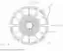
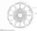
FIG. 1 shows a rotor 1, which in the illustrated version is designed as a device for converting mechanical energy into heat energy (and vice versa). The rotor 1 is used in particular as a rotary heat pump. Depending on the embodiment, the rotor 1 may be accommodated in a stationary housing in which the pressure is below atmospheric. The rotor 1 comprises a rotational axis 2, preferably horizontal in the operating state, about which the rotor 1 is rotated with the aid of a motor 37. To form the rotational axis 2, the rotor 1 comprises two rotary bearings 3. The rotor 1 comprises a rotor element 4, shown only symbolically in FIG. 1, which is connected on one side to connections 5 for a heat transfer medium, in particular water, and on the other side to connections 6 for a working medium, for example a noble gas. Furthermore, a fan 7 is provided to maintain a circular flow of the working medium. The fan 7 is connected to a fan drive 8 in order to rotate a blade wheel of the fan 7 relative to the rotor element 4 set in rotation by the motor 37. Furthermore, rotary feedthroughs 9 for the (water) connections 5 can be seen in FIG. 1.
FIG. 2A, FIG. 2B and FIG. 3 schematically show an embodiment of the rotor element 4, which is made up of a plurality of first rotor plates 10 and second rotor plates 11. For the sake of clarity, only two first rotor plates 10 and two second rotor plates 11 are shown in FIG. 2. In FIG. 3, the flow of the working medium is illustrated with solid lines and the flow of the heat transfer medium is illustrated with dashed lines. The first rotor plates 10 and the second rotor plates 11 are connected to each other on their outer surfaces parallel to their (in operation vertically aligned) main extension or plate planes. The first 10 and the second rotor plates 11 alternate when looked at in the axial direction. In this embodiment, the first rotor plates 10 each comprise several flow ducts 12 through which the working medium flows. The working medium flows into an inlet opening 13 into an initial section of the flow duct 12 and out of an end section of the flow duct 12 via an outlet opening 14. In the embodiment shown, several adjacent flow ducts 12 running parallel to each other are provided per inlet opening 13, cf. the detail B of FIG. 2B highlighted with a circle in FIG. 2A. The inlet openings 13 are connected to an outlet of the fan 7. The outlet openings 14 are connected to an inlet of the fan 7. In the example shown, the outlet openings 14 are arranged in the central regions of the first rotor plates 10 through which the rotational axis 2 passes. To form a compression duct 15, the flow duct 12 comprises a flow duct section 16 leading essentially radially outwards, in which the working medium is guided away from the rotational axis 2 to increase the pressure due to the centrifugal acceleration. The essentially radially outward running flow duct section 16 is adjoined by at least one flow duct section 17 running essentially in the circumferential direction, with which a first heat transfer duct 18 is formed for heat exchange with the heat transfer medium. The circumferential flow duct section 17 is adjoined by a flow duct section 19 running essentially radially inwards, which acts as an expansion duct 20 to reduce the pressure of the working medium due to centrifugal acceleration. The flow duct section 19 leading essentially radially inwards is adjoined by at least one further flow duct section 21 running essentially in the circumferential direction, which is designed as a further first heat transfer duct 18 for heat exchange with the heat transfer medium. The inlet openings 13 and the outlet openings 14 of the first rotor plates 10 are each arranged in alignment. The second rotor plates 11 comprise corresponding pass-through openings 32 for the working medium to pass through.
In this embodiment, the second rotor plates 11 each comprise second heat transfer ducts 22 through which the heat transfer medium flows. As second heat transfer ducts 22, the second rotor plates 11 each comprise at least one inner flow duct 23 with at least one section 24 running in the circumferential direction to form an inner heat exchanger and at least one outer flow duct 25 with a section 26 running in the circumferential direction to form an outer heat exchanger. Seen in the radial direction, the outer flow duct 25 is arranged further outwards than the inner flow duct 23. The circumferentially running section 24 of the inner flow duct of the second rotor plate 11 extends next to the circumferentially running flow duct section 21 of the first rotor plate 10. The circumferentially running section 26 of the outer flow duct of the second rotor plate 11 extends next to the circumferentially running flow duct section 17 of the first rotor plate 10. The inner flow duct 23 of the second rotor plate 11 comprises an inlet opening 27 for the entry of the heat transfer medium and an outlet opening 28 for the exit of the heat transfer medium. Correspondingly, the outer flow duct 25 comprises a further inlet opening 29 for the entry of the heat transfer medium and a further outlet opening 30 for the exit of the heat transfer medium. The inlet openings 27, the outlet openings 28, the further inlet openings 29 and the further outlet openings 30 are each arranged in alignment. The first rotor plates 10 comprise corresponding feed-through openings 31 for the passage of the heat transfer medium.
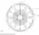
In the embodiment of FIG. 2A, FIG. 2B and FIG. 3, the first 10 and the second rotor plates 11 are circular in the direction of view of the rotational axis 2. Each of the first rotor plates 10 comprises several, for example 12, flow ducts 12, which are identically formed and distributed at different angular positions over the first rotor plates 10. As mentioned above, a plurality of flow ducts 12 can also be provided at each angular position, which extend side by side from the inlet opening 13 to the outlet opening 14. In the embodiment shown, the flow ducts 12 comprise a plurality of flow duct sections 21 running in the circumferential direction in a radially inner region of the first rotor plate 10 and a plurality of flow duct sections 17 running in the circumferential direction in a radially outer region of the first rotor plate 10, which are each arranged in loops at different radii R1, R2, R3 relative to the rotational axis 2. Accordingly, the second rotor plates 11 comprise several, for example 12, inner flow ducts 23 and several, for example 12, outer flow ducts 24. In the embodiment shown, the inner flow ducts 23 of the second rotor plates 11 each comprise a plurality of circumferentially running sections 24 as inner heat exchangers and a plurality of circumferentially running sections 26 as outer heat exchangers, which extend next to the circumferentially running flow duct sections 21 in the radially inner region of the first rotor plate 10 or next to the circumferentially running flow duct sections 17 in the radially outer region of the first rotor plate 10. In the embodiment of FIGS. 2A, 2B and FIG. 3, the working medium is compressed or expanded during heat transfer.
FIG. 4 shows a further embodiment, exemplified by one of the first rotor plates 10, in which two adjacent flow ducts 12 are arranged mirrored with respect to a plane of symmetry S extending in the axial and radial directions. The two adjacent flow ducts 12 each share a common inlet opening 13 and a common outlet opening 14 for the working medium. In this embodiment, the flow ducts of the second rotor plates 11 run congruently with the flow ducts 12 of the first rotor plates 10 in the area of the heat transfer ducts and are preferably run through in counterflow.
FIG. 5, FIG. 6 and FIG. 7 each show a further embodiment in which the working medium is compressed or expanded during the heat transfer.
According to FIG. 5, the working medium is compressed during the external heat transfer, preferably in order to achieve low temperature differences between the working medium and the heat transfer medium on the sink side at low spreads or at an essentially constant temperature of the heat transfer medium on the sink side.
Furthermore, the working medium is expanded during internal heat transfer in order to achieve a low temperature difference between the working medium and the heat transfer medium on the source side at low spreads or at an essentially constant temperature of the heat transfer medium on the source side. Low temperature differences between the working medium and the respective heat transfer medium lead to low exergy losses and a high efficiency (COP) of the entire system. The prerequisite is that the respective heat transfer medium is fed through the ducts with the working medium using the counterflow principle.
According to FIG. 6, the working medium is compressed during the external heat transfer, preferably in order to achieve low temperature differences between the working medium and the heat transfer medium on the sink side at low spreads or at an essentially constant temperature of the heat transfer medium on the sink side.
Furthermore, the working medium is also compressed during internal heat transfer in order to achieve a low temperature difference between the working medium and the heat transfer medium on the source side when the heat transfer medium on the source side has a high spread. The respective heat transfer medium and the working medium are guided through the ducts using the counterflow principle.
According to FIG. 7, the working medium is expanded during the external heat transfer in order to achieve low temperature differences between the working medium and the heat transfer medium on the sink side when the heat transfer medium on the sink side has a high spread.
Furthermore, the working medium is compressed during the internal heat transfer in order to achieve a low temperature difference between the working medium and the heat transfer medium on the source side when the heat transfer medium on the source side has a high spread. The respective heat transfer medium and the working medium are guided through the ducts using the counterflow principle.
FIG. 8 shows a further embodiment in which no intermediate compression or intermediate expansion of the working medium takes place. For this purpose, the working medium flows through only one flow duct section 21 running in circumferential direction per flow duct 12 in the radially inner region of the first rotor plate 10, i.e. not several flow sections 21 connected to one another in loops as in FIG. 2A, FIG. 2B and FIG. 3. Accordingly, the working medium in the radially outer region of the first rotor plate 10 flows through only one flow duct section 17 running in the circumferential direction per flow duct 12, i.e. not several flow duct sections 17 connected to one another in loops as in FIG. 2A, FIG. 2B and FIG. 3.
FIG. 9 shows a further embodiment in which the first rotor plates 10 and/or the second rotor plates 11 each comprise at least one recess 33. The recesses 33 can be arranged in such a way that heat transfer between the flows of the working medium in flow ducts 12 at different angular positions of the respective first rotor plates 10 is reduced, in particular essentially inhibited. Furthermore, the recesses 33 can be used to reduce, in particular essentially inhibit, the heat transfer of the heat transfer media in the flow ducts of the second rotor plates 11 at neighboring ducts. Furthermore, the recesses 33 can be arranged in such a way that the heat transfer between the working medium and the heat transfer medium can essentially only take place at those locations at which the heat transfer is desired.
FIG. 10A shows a first embodiment in which the first 10 and the second rotor plates 11 are non-circular, here essentially rectangular, when viewed in the direction of the rotational axis 2. In the embodiment shown, the two shorter sides of the first 10 or second rotor plates 11 are formed in a curved manner and the two longer sides of the first 10 or second rotor plates 11 are formed in a straight manner.
FIG. 10B and FIG. 10C show another essentially rectangular embodiment of the rotor element. In FIG. 10B, one of the first rotor plates 10 is shown, with the ducts of the adjacent second rotor plate 11 drawn in dashed lines. FIG. 10C shows the second rotor plates 11. This embodiment results in the following differences to the embodiments described above.
As can be seen from FIG. 10B, in this embodiment the first rotor plate 10 comprises a plurality of flow ducts 12 for the working medium, preferably extending between 10 and 200, preferably essentially parallel, which extend between the inlet openings 13 and at least one outlet opening 14, here a common outlet opening 14. For the sake of clarity, seven flow ducts 12 per quarter of the first rotor plates 10, i.e. a total of 28 flow ducts 12, are illustrated in FIG. 10B. The flow ducts 12 each comprise one of the compression ducts 15 leading outwards away from the rotational axis 2, an outer one of the first heat transfer ducts 18, an expansion duct 20 and an inner one of the first heat transfer ducts 18. The first heat transfer ducts 18 for forming the outer heat exchanger and the first heat transfer ducts 18 for forming the inner heat exchanger are each arranged at different distances from the rotational axis 2. The first heat transfer ducts 18 on the outside are each connected to the corresponding first heat transfer ducts 18 on the inside, so that the differences in the distances from the rotational axis 2 are essentially the same. Thus, for example, the innermost duct of the parallel first heat transfer ducts 18 of the inner heat transfer, leading essentially in the circumferential direction, is also connected to the innermost duct of the parallel first heat transfer ducts 18 of the outer heat transfer, leading essentially in the circumferential direction. The two radii of the connected inner and outer heat transfer ducts 18 are designed so that the temperature difference between the inner and outer heat transfer ducts is essentially the same in all parallel ducts. This enables essentially the same temperature curves and constant heat transfer performance in all parallel heat transfer ducts, which keeps exergy losses low and prevents preferential flow due to increased or decreased pressure difference.
Furthermore, in the embodiment of FIGS. 10B, 10C, the working medium flows transversely to the heat transfer medium in the heat transfer area, whereby low temperature differences (and thus low exergy losses) nevertheless occur. In FIG. 10A, this is shown using the external heat transfer by compressing the working medium in each of the parallel ducts during the heat exchange in such a way that a constant temperature is established in this duct. The temperature spread for the crossflowing heat transfer medium can be set via the number and radius difference in the heat transfer area of the parallel ducts. Due to the high number of parallel ducts (with the same radial extension as in the designs with loops described above) and the comparatively short duct length, the pressure loss is reduced compared to the other designs. The same effect can be achieved in the area of internal heat transfer if each of the parallel inner ducts is expanded during the heat exchange with the heat transfer medium via a radius reduction in the direction of flow in such a way that the temperature within a duct is kept constant.
In FIG. 11 and FIG. 12, a part of the rotor element 4 of the embodiment according to FIG. 2A, FIG. 2B and FIG. 3 is shown in greater detail. Accordingly, several, in the shown example six, flow duct sections 21 essentially in circumferential direction in the radially inner area, flow duct sections 17 essentially in circumferential direction in the radially outer area of the first rotor plates 10, sections 24 of the inner heat exchanger essentially in circumferential direction and sections 26 of the outer heat exchanger of the second rotor plates 11 essentially the circumferential direction extend next to each other. Furthermore, an end plate 34 without ducts can be seen in FIG. 9 and FIG. 10.
As FIG. 11 and FIG. 12 show, the flow ducts 12 of the first rotor plates 10 and the second heat transfer ducts 22 of the second rotor plates 11 are each formed as indentations 35, which are recessed relative to the flat outer or bonding surfaces 36 of the first 10 and second rotor plates 11 respectively. The closed ducts for the working and heat transfer medium respectively are formed by stacking the first 10 and second rotor plates 11. The first rotor plates 10 and the second rotor plates 11 can be connected to each other via diffusion connections. These connections are described, for example, in EP 3 885 691.
In FIG. 13 and the detailed view of FIG. 14 marked with a rectangle in FIG. 13, a further embodiment of the rotor is shown, whereby only the differences to the preceding embodiments are discussed below. In the embodiment of FIG. 13 and FIG. 14, the first rotor plates 10 comprise not only the compression ducts 15, the expansion ducts 20 and the first heat transfer ducts 18 for the working medium, but also the second heat transfer ducts 22 for the heat transfer medium. For this purpose, the first rotor plates 10 comprise on their first outer surfaces 36A the indentations 35 for forming the compression ducts 15, the expansion ducts 20 and the first heat transfer ducts 18 for the working medium and on their second outer surfaces 36B indentations 35 for forming the second heat transfer ducts 22 for the heat transfer medium. The second rotor plates 11 are arranged between the first rotor plates 10 as separating plates free of the indentations 35, in order to close off the indentations 35 of the first rotor plates 10 in order to form the flow ducts 12 and the second heat transfer ducts 22.
REFERENCE NUMBER LIST
-
- 1 Rotor
- 2 Rotational axis
- 3 Rotary bearings
- 4 Rotor element
- 5 Water connections
- 6 Gas connections
- 7 Fan
- 8 Fan drive
- 9 Rotary feedthroughs
- 10 First rotor plates
- 11 Second rotor plates
- 12 Flow ducts of the first rotor plates 10
- 13 Inlet openings of the flow ducts 12
- 14 Outlet openings of the flow ducts 12
- 15 Compression duct
- 16 Radially outward running flow duct section
- 17 Circumferentially running flow duct section
- 18 First heat transfer duct
- 19 Radially inward running flow duct section
- 20 Expansion duct
- 21 Circumferentially running flow duct sections
- 22 Second heat transfer ducts
- 23 Inner flow ducts of the second rotor plates 11
- 24 Circumferentially running sections of the inner flow ducts
- 23
- 25 Outer flow ducts of the second rotor plates 11
- 26 Circumferentially running sections of the outer flow ducts
- 25
- 27 Inlet openings
- 28 Outlet openings
- 29 Further inlet openings
- 30 Further outlet openings
- 31 Feed-through openings of the first rotor plates 10
- 32 Pass-through openings of the second rotor plates 11
- 33 Recesses
- 34 End plate
- 35 Indentations
- 36 Exterior or bonding surfaces
- 37 Motor
Claims
What is claimed is:1. Rotor (1), comprising a rotary heat pump, comprising:
a rotational axis (2),
a number of compression ducts (15) in which a working medium, comprising a gas, is guided away from the rotational axis (2) to increase the pressure due to the centrifugal acceleration,
a number of expansion ducts (20) in which the working medium is guided towards the rotational axis (2) to reduce the pressure due to centrifugal acceleration,
a number of first heat transfer ducts (18) for the working medium and
a number of second heat transfer ducts (22) for a heat transfer medium, comprising a liquid, so that heat is transferred between the working medium flowing in the first heat transfer ducts (18) and the heat transfer medium flowing in the second heat transfer ducts (22),
wherein
a number of first (10) and second rotor plates (11) comprising the compression ducts (15), the expansion ducts (20), the first heat transfer ducts (18) for the working medium and the second heat transfer ducts (22) for the heat transfer medium,
wherein the first (10) and second rotor plates (11) are connected to each other along their main planes of extension.
2. The rotor (1) according to claim 1, wherein wherein
the number of first rotor plates (10) each comprise at least one of the compression ducts (15), at least one of the expansion ducts (20) and at least one of the first heat transfer ducts (18) for the working medium and
the number of second rotor plates (11) each comprise at least one of the second heat transfer ducts (22) for the heat transfer medium.
3. The rotor (1) according to claim 2, wherein
the first rotor plates (10) each comprise at least one flow duct (12)
with an essentially radially outward running flow duct section (16) to form one of the compression ducts (15) and/or
with an essentially radially inward running flow duct section (19) to form one of the expansion ducts (20) and/or
with an essentially circumferentially running flow duct section (17, 21) to form one of the first heat transfer ducts (18),
wherein the at least one flow duct (12) comprises an inlet opening (13) for the working medium at a first end and an outlet opening (14) for the working medium at a second end.
4. The rotor (1) according to claim 1, wherein a fan (7) is provided for maintaining the flow of the working medium, the inlet openings (13) being connected to an outlet of the fan (7) and/or the outlet openings (14) being connected to an inlet of the fan (7).
5. The rotor (1) according to claim 2, wherein the first rotor plates (10) each comprise a plurality of flow ducts (12), each with at least one flow duct section (16) running essentially radially outwards and/or with at least one flow duct section (19) running essentially radially inwards and/or with at least one flow duct section (17, 21) running essentially in the circumferential direction.
6. The rotor (1) according to claim 5, wherein the flow ducts (12) of the first rotor plates (10) each comprise a plurality of flow duct sections (17, 21), running essentially in the circumferential direction, at different radial distances from the rotational axis (2) in order to form a plurality of first heat transfer ducts (10).
7. The rotor (1) according to claim 5, wherein two adjacent flow ducts (12) of the first rotor plates (10) are arranged mirrored with respect to a plane of symmetry spanned in the axial and radial directions, the two adjacent flow ducts (12) sharing a common inlet opening (13) and a common outlet opening (14) for the working medium.
8. The rotor (1) according to claim 1, wherein the second rotor plates (11) each comprise at least one inner flow duct (23) and at least one outer flow duct (25), each for forming one of the second heat transfer ducts (22), the outer flow duct (25) being arranged further outwards in the radial direction than the inner flow duct (23).
9. The rotor (1) according to claim 1, wherein the first rotor plates (10) comprise the second heat transfer ducts (22) for the heat transfer medium.
10. The rotor (1) according to claim 1, wherein the compression ducts (15), the expansion ducts (20) and the first heat transfer ducts (18) for the working medium are formed as indentations (35) starting from an essentially flat first outer surfaces (36A) of the first rotor plates (10), whereby the second heat transfer ducts (22) for the heat transfer medium are formed
i. as indentations (35) starting from an essentially flat outer surfaces (36) of the second rotor plates (11) or
ii. as indentations (35) starting from an essentially flat second outer surfaces (36B) of the first rotor plates (10).
11. The rotor (1) according to claim 1, wherein the first rotor plates (10) and the second rotor plates (11) are connected to one another via diffusion connections.
12. The rotor (1) according to claim 1, wherein the first (10) and the second rotor plates (11) are each essentially circular or non-circular, and essentially rectangular.
13. Method of manufacturing a rotor (1), comprising a rotary heat pump, comprising the steps:
Provision of first rotor plates (10),
provision of second rotor plates (11),
forming compression ducts (15), expansion ducts (20), first heat transfer ducts (18) for a working medium and second heat transfer ducts (22) for a heat transfer medium in the first rotor plates (10) and/or in the second rotor plates (11),
stacking the first (10) and second rotor plates (11), connecting the first rotor plates (10) to the second rotor plates (11) along their main planes of extension, and
rotary bearing of a rotor element (4) formed from the first (10) and the second rotor plates (11) about a rotational axis (2).
14. The method according to claim 13, wherein the first rotor plates (10) and the second rotor plates (11) are joined together by diffusion bonding.
15. The method according to claim 13, wherein the compression ducts (15), the expansion ducts (20), the first heat transfer ducts (18) and/or the second heat transfer ducts (22) are formed by etching or milling in the first and/or in the second rotor plates (11).
Images & Drawings included:


Sources:
- United States Patent and Trademark Office - verify current appl. status at the USPTO↗
Similar patent applications:
- » 20150262772
Rotor shaft module for a rotor shaft of a molded-case circuit breaker, rotor shaft for a molded-case circuit breaker, molded-case circuit breaker comprising a rotator shaft, and method for producing a rotor shaft module for a rotor shaft of a molded-case circuit breaker - » 20230235672
Rotor with a balancing flange, rotor assembly with at least one rotor, and turbomachine with at least one rotor or with a rotor assembly - » 20180187550
Last turbine rotor disk for a gas turbine, rotor for a gas turbine comprising such last turbine rotor disk and gas turbine comprising such rotor - » 20140072408
Vacuum pump having fastening element for securing rotor part to rotor shaft and deformed safety element projecting in axial direction for preventing relative rotation between the rotor part and rotor shaft - » 20080164780
Rotor for an electric motor, rotor discs for construction of the rotor, and an electric motor having such a rotor - » 20170237369
ELECTRIC POWER-GENERATING SYSTEM FOR A ROTOR BLADE, LIGHTING SYSTEM FOR A ROTOR BLADE, ROTOR BLADE AND ROTOR SYSTEM - » 20120051892
Wind turbine rotor designing method, wind turbine rotor design support device, wind turbine rotor design support program and wind turbine rotor - » 20090225624
Homogenizer device having a rotor and an advance wheel (inducer screw) that can rotate opposite to the rotor and a counter-current rotor that can rotate opposite to the rotor - » 20130187512
Rotor bar for squirrel-cage rotor, and squirrel-cage rotor provided with rotor bar - » 20150232304
Lifter and method for handling a rotor blade, rotor blade for a wind generator and method for marking a rotor blade, system comprising a lifter and a rotor blade
Recent applications in this class:
- » 20240302103 2024-09-12
FIXING DEVICE FOR REINFORCING THE JOINT OF A ROTARY HEAT EXCHANGER - » 20230349642 2023-11-02
Heat exchanger and use of heat exchanger - » 20200049414 2020-02-13
Heat transfer devices and methods for facilitating convective heat transfer with a heat source or a cold source - » 20200025456 2020-01-23
ROTATING HEAT EXCHANGER WITH TUBE COIL - » 20180187976 2018-07-05
Rotary heat exchanger - » 20160169590 2016-06-16
Chemical heat storage device - » 20160091255 2016-03-31
Rotary high density heat exchanger - » 20120132398 2012-05-31
SYSTEMS AND METHODS OF THERMAL ENERGY STORAGE AND RELEASE - » 20120037340 2012-02-16
Heat Exchange Fan Apparatus - » 20110209475 2011-09-01
High temperature solar thermal systems and methods