FACILITIES DOSING SYSTEM
US20260043552A1
2026-02-12
18/795,542
2024-08-06
Smart Summary: A facilities dosing system uses a special valve to control hot water flow from a heater to various fixtures. This system can flush drainage pipes with hot water to keep them clean. A controller manages when the valve opens, allowing for timed flushing. It can repeatedly trigger this process to ensure the drainage stays clear. The system also avoids using cold water from storage tanks during this flushing. 🚀 TL;DR
Abstract:
A facilities dosing system comprises a signal-actuated valve controlling a flow of hot water from a water heater to one or more water fixtures that drain to one or more drainage conduits, and a controller configured to trigger opening of the signal-actuated valve, allowing for flushing with the hot water of the drainage conduits from the one or more water fixtures over a controlled period of time. A facilities dosing method comprises electronically controlling, by a system comprising a controller, flow of hot water from a water heater to a plurality of water fixtures that have automatically-allowed drainage to drainage conduits, and cyclically electronically triggering, by the system, the electronic controlling, for repeated flushing of the drainage conduits with the hot water, comprising bypassing cold water cisterns feeding the water fixtures.
Inventors:
- Robert White 1 🇬🇧 Flitwick, United Kingdom
- Robbie Graham 1 🇬🇧 Bushey, United Kingdom
- Lewis Bulled 1 🇬🇧 Kings Langley, United Kingdom
Applicant:
Interested in similar patents?
Get notified when new applications in this technology area are published.
Classification:
F24D19/1051 » CPC main
Details; Arrangement or mounting of control or safety devices for water heating systems for domestic hot water
E03D13/00 » CPC further
Urinals ; Means for connecting the urinal to the flushing pipe and the wastepipe; Splashing shields for urinals
F24D2220/044 » CPC further
Components of central heating installations excluding heat sources; Sensors Flow sensors
F24D19/10 IPC
Details Arrangement or mounting of control or safety devices
Description
BACKGROUND
In a facilities maintenance environment, non-use of water fixtures can lead to difficulty maintaining continued water flow, preventing clogging, preventing calcification, and/or the like. Non-use can lead to higher maintenance, more frequent maintenance, and/or increased parts replacement. Further, use of chemicals in facilities maintenance is becoming less desirable due to recognition of environmental impact and concerns related thereto.
SUMMARY
The following presents a summary to provide a basic understanding of one or more embodiments described herein. This summary is not intended to identify key or critical elements, and/or to delineate scope of particular embodiments or scope of claims. Its sole purpose is to present concepts in a simplified form as a prelude to the more detailed description that is presented later. In one or more embodiments, systems, methods and/or apparatuses described herein can provide a facilities maintenance system that can be employed in a retrofit manner with varying facilities fixture and/or hardware setups. In one or more other embodiments, systems, methods and/or apparatuses described herein can provide a facilities maintenance system comprising at least one water fixture and/or water heater, and thus can be employed in a non-retrofit manner for facilities maintenance.
As used herein, the term “facilities” can refer to bathroom, water closet, kitchen, and/or other plumbing systems, fixtures, apparatuses, etc. It will be appreciated that such facilities can function with and/or comprise one or more electronic, chemical and/or HVAC elements.
In accordance with an embodiment, a system can comprise an electronically-actuatable valve controlling a flow of hot water from a water heater to one or more water fixtures that drain to one or more drainage conduits, and a controller configured to trigger opening of the electronically-actuatable valve, allowing for flushing with the hot water of the drainage conduits from the one or more water fixtures over a controlled period of time.
In accordance with another embodiment, a system can comprise a sparge conduit arranged to feed a water fixture from a water heater while bypassing a water cistern of the water fixture, and a flow control device coupled along a path of flow between the water heater and a water outlet of the water fixture, wherein flow to the sparge conduit from the water heater is controllable by the flow control device to control repeated flow of hot water, from the water heater, to a drainage conduit of the water fixture, over an electronically-specified time period.
In accordance with still another embodiment, a method of facilities maintenance comprises electronically controlling, by a system comprising a controller, flow of hot water from a water heater to a plurality of water fixtures that have automatically-allowed drainage to drainage conduits, and cyclically electronically triggering, by the system, the electronic controlling, for repeated flushing of the drainage conduits with the hot water, comprising bypassing cold water cisterns feeding the water fixtures.
A benefit of the systems and/or methods of facilities maintenance described herein can be an ability to provide proactive facilities cleaning as compared to reactive facilities cleaning (as is employed with existing frameworks for facilities cleaning). That is, the one or more embodiments described herein can be automatically employed, and automatically triggered, to dose one or more water fixtures with hot water for facilitating repeated and/or scheduled cleaning of drain conduits, such as drainage conduits of the one or more water fixture. This can relieve clogging, such as due to calcification, uric acid, foreign materials, etc.
Furthermore, in that the one or more embodiments can be performed automatically, this can reduce labor, parts cost, replacement cost, time and/or other investments conventionally related to facilities maintenance of water fixtures or other plumbing fixtures.
Another benefit of the systems and/or methods of facilities maintenance described herein can be an ability to employ the one or more frameworks described herein in a retrofit, new use and/or plug-and-use manner. That is, the one or more embodiments described herein can be employed with varying water fixture, plumbing systems, etc., of varying make, manufacture, brand, type, pressure rating, etc. These varying water fixtures can be already in place and/or in use, and/or such varying water fixtures can be newly fitted. In one or more embodiments a facilities dosing system described herein can comprise a water fixture for being maintained by the facilities dosing system.
Likewise, the one or more embodiments described herein can be employed with an in-use facility and/or building or with a facility and/or building that is not in use. Indeed, relative to a facility or portion thereof that is not in use, the one or more embodiments described herein can provide significant cost, time and/or labor savings. This can be as compared to a need to manually flush water fixtures associated therewith for maintaining good function of the water fixtures while the facility or portion thereof is not in use.
Still another benefit of the systems and/or methods of facilities maintenance described herein can be an ability to employ hot water for the dosing, absent use of corrosive, toxic and/or environmentally-unfriendly chemicals that are conventionally employed for drainage and/or flow issues associated with water fixtures and/or other plumbing systems.
Structurally, a facilities dosing system described herein can be arranged within an architectural structure, such as accompanying cisterns for the water fixtures being maintained by the facilities dosing system. That is, the one or more systems described herein can be employed absent being viewed and/or undesirably adjusted by non-maintenance entities.
DESCRIPTION OF THE DRAWINGS
FIG. 1 illustrates a block diagram of an example, non-limiting system for facilities dosing, in accordance with one or more embodiments described herein.
FIG. 2 illustrates a block diagram of another example, non-limiting system for facilities dosing, in accordance with one or more embodiments described herein.
FIG. 3 illustrates a block diagram of yet another example, non-limiting system for facilities dosing, in accordance with one or more embodiments described herein.
FIG. 4 provides a schematic illustration of an example, facilities dosing system, corresponding to any one or more of FIGS. 1-3, employed in a water delivery system, in accordance with one or more embodiments described herein.
FIG. 5 provides a schematic illustration of another example, facilities dosing system, corresponding to any one or more of FIGS. 1-3, employed in a water delivery system, in accordance with one or more embodiments described herein.
FIG. 6 provides a flow diagram of a set of example processes for facilities dosing system operation, corresponding to a facilities dosing system of any of FIGS. 1-3, in accordance with one or more embodiments described herein.
FIG. 7 illustrates a flow diagram of one or more example processes of a method of operation of the example, non-limiting systems of FIGS. 1-3, in accordance with one or more embodiments described herein.
FIG. 8 illustrates a continuation of the flow diagram of FIG. 7 of the one or more example processes of the method of operation of the example, non-limiting systems of FIGS. 1-3, in accordance with one or more embodiments described herein.
FIG. 9 illustrates a schematic block diagram of an example networking environment into which and/or with which the embodiments of the subject matter described herein can be incorporated.
FIG. 10 illustrates a block diagram of an example computing environment with which the subject matter described herein can interact and/or be implemented at least in part.
DETAILED DESCRIPTION
The following detailed description is merely illustrative and is not intended to limit embodiments and/or application or utilization of embodiments. Furthermore, there is no intention to be bound by any expressed or implied information presented in the preceding Summary section, or in the Detailed Description section. One or more embodiments are now described with reference to the drawings, wherein like reference numerals are utilized to refer to like elements throughout. In the following description, for purposes of explanation, numerous specific details are set forth in order to provide a more thorough understanding of the one or more embodiments. It is evident, however, in various cases, that the one or more embodiments can be practiced without these specific details.
Various operations can be described as multiple discrete actions or operations in turn, in a manner that is most helpful in understanding the subject matter disclosed herein. However, the order of description should not be construed as to imply that these operations are necessarily order dependent. In particular, these operations can be performed in an order different from the order of presentation. Operations described can be performed in a different order from the described embodiment. Various additional operations can be performed, and/or described operations can be omitted in additional embodiments.
In existing frameworks, issues with drainage of drainage conduits is typically communicated manually, such as by word of mouth, email, etc. Reactive maintenance then includes heavy use of chemical agents, manual labor, unscheduled time to address, and overall, is inefficient and costly. By responding reactively to drainage concerns, the issue itself is able to be compounded, which can include, but is not limited to corrosion, calcification and/or other breakdown of parts, components, etc., which can require repair and/or replacement.
In existing cases of non-use for a period of time of one or more facilities, these issues also can be compounded, due to stagnation and lack of flow. Likewise, response is typically wholly reactive, such as when the one or more facilities are again planned for use or first put into use again. By this time, any drainage issue can have already manifested and/or compounded itself, without an administrator entity and/or maintenance entity being made aware. As with other cases, this can lead to, but is not limited to corrosion, calcification, and/or other breakdown of parts, components, etc., which can require repair and/or replacement.
Indeed, in cases of existing frameworks, the only options that can be available to maintenance entities and/or administrator entities can be flushing with the cold water supply typically employed for normal water flushing, with or without addition of a chemical agent, and/or plumbing repair requiring manually removing conduit. The latter option can be time and labor intensive, and can require downtime of the facilities and/or architectural structure repair, such as to allow for access to one or more conduits.
Further, in existing frameworks, these limited options are typically employed during use hours of typical access to the facilities by user entities. That is, maintenance during non-use hours can be difficult, expensive, or not possible due to lack of access, supervision, etc. Accordingly, existing reactive responses to drainage issues therefor usually involve downtime and/or closing of the facilities, further exacerbating the issues already compounded by the drainage itself (e.g., failure to function, overflow, cleanup, etc.).
To account for one or more deficiencies of such existing frameworks, one or more embodiments are described herein that can provide proactive dosing with hot water of drainage pipes of facilities, such as water fixtures, such as based on a schedule. A system described herein can be employed with new facilities, retrofit into and/or with existing facilities, and/or employed with varying water fixture types, brands, makes, models, materials, etc. In one or more embodiments, hot water flushing can be triggered based on a controller, timing element and flow control device such as a signal-actuated valve. This triggering can be executed relative to one or more different drainage conduits, and thus relative to one or more water fixtures.
In one or more embodiments, components of a system described herein can be stored within an architectural structure (e.g., a wall, closet, facilities maintenance room) and thus can be out of sight from user entities of the water fixtures.
Generally, the one or more embodiments described herein can be employed to provide an environmentally-sound alternative to chemical dosing of facilities. The frameworks described herein can be employed for automatic and proactive maintenance of one or more facilities (e.g., water fixtures), thus reducing labor, time, energy, cost, part replacement, part repair, etc. that accompanies existing frameworks for facilities dosing.
Further, the one or more embodiments described herein are not limited to water fixtures such as bathroom and/or kitchen water fixtures. Rather, the one or more embodiments described herein can be applied to other facilities comprising plumbing fixtures, conduits, piping, HVAC fixtures, passive and/or active drainage conduits, etc.
As used herein, the phrase “based on” should be understood to mean “based at least in part on,” unless otherwise specified.
As used herein, the term “component” can refer to an atomic element, molecular element, phase of an atomic or molecular element, or combination thereof. As used herein, the term “data” can comprise metadata.
As used herein, the terms “entity,” “administrator entity,” “maintenance entity,” and/or “user entity” can refer to a machine, device, component, hardware, software, smart device, party, organization, individual and/or human.
As used herein, and noted above, the term “facilities” can refer to bathroom, kitchen, and/or other plumbing systems, fixtures, apparatuses, etc. It will be appreciated that such facilities can function with and/or comprise one or more electronic, chemical and/or HVAC elements.
One or more embodiments are now described with reference to the drawings, where like referenced numerals are used to refer to like drawing elements throughout. In the following description, for purposes of explanation, numerous specific details are set forth in order to provide a more thorough understanding of the one or more embodiments. It is evident in various cases, however, that the one or more embodiments can be practiced without these specific details.
Further, it should be appreciated that the embodiments depicted in one or more figures described herein are for illustration only, and as such, the architecture of embodiments is not limited to the systems, devices and/or components depicted therein, nor to any particular order, connection and/or coupling of systems, devices and/or components depicted therein.
Referring now to FIGS. 1 to 3, in one or more embodiments, the example, non-limiting systems 100, 200 and/or 300 illustrated at FIGS. 1 to 3, and/or systems thereof, can comprise one or more computer and/or computing-based elements described herein. In one or more cases, such one or more computer and/or computing-based elements can be employed with a networking environment 900 (e.g., FIG. 9) and/or computing environment 1000 (e.g., FIG. 10) to be described below. In one or more described embodiments, computer and/or computing-based elements can be used in connection with implementing one or more of the systems, devices, components and/or computer-implemented operations shown and/or described (e.g., at FIGS. 4 to 7) in connection with FIGS. 1 to 3 and/or with other figures described herein, as well as other implementations not explicitly depicted in the non-limiting example figures herein.
Turning first to FIG. 1, the figure illustrates a block diagram of an example, example, non-limiting system 100 that can comprise a facilities dosing system 102. The facilities dosing system 102 can generally facilitate dosing of one or more facilities for proactive flushing thereof.
One or more communications between one or more components of the example, non-limiting system 100 can be provided by wired and/or wireless means including, but not limited to, employing a cellular network, a wide area network (WAN) (e.g., the Internet), and/or a local area network (LAN). Suitable wired or wireless technologies for supporting the communications can include, without being limited to, wireless fidelity (Wi-Fi), global system for mobile communications (GSM), universal mobile telecommunications system (UMTS), worldwide interoperability for microwave access (WiMAX), enhanced general packet radio service (enhanced GPRS), third generation partnership project (3GPP) long term evolution (LTE), third generation partnership project 2 (3GPP2) ultra-mobile broadband (UMB), high speed packet access (HSPA), Zigbee and other 802.XX wireless technologies and/or legacy telecommunication technologies, BLUETOOTH®, Session Initiation Protocol (SIP), ZIGBEE®, RF4CE protocol, WirelessHART protocol, 6LoWPAN (Ipv6 over Low power Wireless Area Networks), Z-Wave, an advanced and/or adaptive network technology (ANT), an ultra-wideband (UWB) standard protocol and/or other proprietary and/or non-proprietary communication protocols.
The facilities dosing system 102 can be associated with, such as accessible via, a cloud computing environment, such as the networking environment 900 of FIG. 9.
The facilities dosing system 102 can comprise at least a controller 120 having a memory 120M, processor 120P, and/or timing element 122. The processor 120P can be any suitable processor, such as a field programmable gate array (FPGA), microprocessor, multi-processor and/or any other suitable programmable electronics. The memory 120M can provide any suitable storage and can be any suitable element such as a random access memory, read-only memory, erasable programmable read-only memory, static random access memory, hard drive, solid-state drive, flash drive, memory stick, memory card reader, and/or other nonvolatile memory element, tangible and/or non-transitory media and/or element. In one or more embodiments, the processor 120P and/or the memory 120M can comprise the timing element 122.
In one or more embodiments, the facilities dosing system 102 can comprise a bus for communicatively connecting the memory 120M, processor 120P and/or timing element 122.
The timing element 122 can be comprised by the controller 120 and/or can be external to the controller 120. The timing element 122 can be any suitable element for performing a clock function, such as to continually count forward in time and/or to count down to a next triggering. The timing element 122 can function separately from and/or be controlled by the controller 120.
In one or more embodiments, the facilities dosing system 102 can be coupled (e.g., communicatively, electrically, operatively, optically and/or like function) to one or more external systems (e.g., a non-illustrated electrical output production system, one or more output targets and/or an output target controller), sources and/or devices (e.g., classical computing devices, communication devices and/or like devices), such as via a network.
In addition to the processor 120P and/or memory 120M described above, the facilities dosing system 102 can comprise one or more computer and/or machine readable, writable and/or executable components and/or instructions that, when executed by processor 120P, can provide performance of one or more operations defined by such component and/or instruction.
It is appreciated that the discussion above relative to the processor 120P, memory 120M and/or bus is equally applicable to the other embodiments described herein, such as those described relative to FIGS. 2 to 5.
Referring still to FIG. 1, the facilities dosing system 102 can comprise one or more flow devices, such as one or more signal-actuated valves 110. Generally, the signal-actuated valve 110 can be actuated by the controller 120 to allow and/or disallow flow from a hot water source to one or more facilities, such as one or more water fixtures, to be dosed with the hot water.
A signal-actuated valve 110 can be a solenoid-actuated valve (e.g., solenoid valve), coaxial valve, gate valve, rotary valve, linear valve, ball valve, plug valve, globe valve, butterfly valve, needle valve, and/or other actuated valve that can be actuated by a signal, such as a communicative and/or electric signal from the controller 120. In one or more cases, the signal-actuated valve 110 can feed one or more sparge conduits and/or water fixtures, where actuation of the signal-actuated valve 110 by the controller, over a specified period of time (e.g., actuation time) can allow for flushing with the one or more sparge conduits and/or water fixtures with the aforementioned hot water flow.
In one or more embodiments, the facilities dosing system 102 can optionally comprise a water heater controller 130. In one or more other embodiments, the controller 120 can provide for control of a water heater, such as a tank-less water heater. Such water heater controller 130, and/or function of the controller 120 can provide for heating water from a temperate and/or cold water supply at any suitable frequency, such as before and/or in parallel with actuation of the signal-actuated valve 110.
In one or more embodiments, the water heater controller 130 can control a temperature of water output from a respective water heater to be within a range of about 50 degrees Celsius to about 55 degrees Celsius.
In one or more embodiments, the facilities dosing system 102 can comprise one or more secondary flow devices, such as one or more flow limiting valves 140. A flow limiting valve 140 can be provided downstream of the signal-actuated valve 110, such as at a sparge conduit extending between the signal-actuated valve 110 and a water fixture. In this way, pressure of water being received at a water fixture, based on actuation of the signal-actuated valve 110, can be controlled.
In one or more embodiments, a flow limiting valve 140 can be manually actuated and/or signal-actuated. Actuation can comprise opening and closing the valve such as at any suitable increment provided by the flow limiting valve 140. In one or more cases, the controller 120 can trigger an adjustment of a flow limiting valve 140, such as in response to a flow sensor employed at a conduit between the flow limiting valve 140 and a position downstream of the flow limiting valve 140 (e.g., a water fixture).
In one or more embodiments, the controller 120 can be configured to trigger opening of the signal-actuated valve 110 over a controlled period of time. The controller 120 can be configured to repeat triggering of the signal-actuated valve 110 over a specified number of cycles. The controller 120 can be configured to trigger a first (e.g., initial) actuation at any suitable frequency, such as plural times an hour, day, week, month, etc. In one or more embodiments, a first actuation can be triggered based on monitoring of usage by the controller 120 having communicative access to a water meter associated with the fixture being maintained.
In one or more example cases, single actuation times can be between about five minutes and about fifteen minutes, such as about ten minutes, as controlled by the controller 120.
In one or more example cases, two to ten actuations, such as five actuations can be controlled by the controller 120.
In correspondence therewith, an actuation can be triggered at a same time or different time each hour by the controller 120. For example, where there are five actuations to be controlled by the controller 120, the controller 120 can trigger an actuation at a same time each hour, for five consecutive hours.
In one or more cases, time between actuations can be controlled, by the controller 120 and/or water heater controller 130, to allow for heat recovery and/or heating element recovery at the associated water heater. For example, a next actuation can be delayed until receipt of information indicating threshold heat recovery and/or heating element recovery.
Additionally, or alternatively, in one or more cases, time between actuations can be controlled, by the controller 120, based on one or more specified times for completing bypassing and/or removal of a blockage at one or more foul drainage conduits 216 (FIG. 2). For example, a next actuation can be delayed until receipt of information indicating threshold flow, or lack thereof due to complete evacuation of the previous dose (e.g., quantity of hot water flushed based on an actuation).
Additionally, or alternatively, in one or more cases, time between actuations can be controlled, by the controller 120, based on information defining flow at one or more foul drainage conduits 216 (FIG. 2), such as based on information from one or more sensors (e.g., sensor or valve 520 at FIG. 5) at the one or more foul drainage conduits 216. For example, a next actuation can be delayed until receipt of information indicating threshold flow, or lack thereof due to complete evacuation of the previous dose.
In one or more cases, one or more signal-actuated valves 110 can be associated with one or more water fixtures 214 (FIG. 2) that have a greater quantity of use by entities. Additionally, and/or alternatively, in one or more cases, usage of one or more water fixtures 214 can vary over time. In such one or more cases, the controller 120 can vary (e.g., increase and/or decrease) any one or more of the following: number of actuations per unit of time, length of one or more actuations, frequency of actuations, etc.
It will be appreciated that any two or more of the above-noted various example cases can be employed at the same time as one another, such as at least partially in parallel with one another.
In one or more cases, a computer device 150, such as separate from the facilities dosing system 102 and/or example, non-limiting system 100, can be communicatively coupled to the controller 120, such as via the processor 120P. In this way, an administrating entity and/or maintenance entity, associated with the computer device 150, can trigger an on-demand flushing using the facilities dosing system 102, and/or can change any one or more parameters employed by the controller 120, such as e.g., actuation length, number of cycles, time period between cycles and/or initial triggering time.
In one or more embodiments, the controller 120 can issue a service reminder to the computer device 150 at any suitable frequency, such as once a month.
In one or more embodiments, the controller 120 and/or water heater controller 130 can issue a low heat notification to the computer device 150, corresponding to low temperature output water from a water heater and/or low heat at the water heater. In correspondence therewith, the notification can comprise a suggestion to re-run one or more actuations based on the low heat notification.
In one or more embodiments, the controller 120 can issue a possible leak notification to the computer device 150, corresponding to low flow at based on information from one or more sensors (e.g., sensor or valve 520 at FIG. 5) at the one or more foul drainage conduits 216. For example, low flow could be based on failure to remove a clog and/or a leak of hot water upstream of the one or more sensors. In correspondence therewith, the notification can comprise a suggestion to re-run one or more actuations based on the low flow notification.
Again, it is appreciated that any two or more of the above-noted various example cases can be employed at the same time as one another, such as at least partially in parallel with one another.
Turning next to FIG. 2, the figure illustrates a block diagram of an example, example, non-limiting system 200 that can comprise a facilities dosing system 202. The facilities dosing system 202 can generally facilitate dosing of one or more facilities for proactive flushing thereof. In one or more embodiments, different from the facilities dosing system 102 of FIG. 1, the facilities dosing system 202 can comprise one or more flow components, as will be described below.
One or more communications between one or more components of the example, non-limiting system 200 can be provided by wired and/or wireless means including, but not limited to, employing a cellular network, a wide area network (WAN) (e.g., the Internet), and/or a local area network (LAN). Suitable wired or wireless technologies for supporting the communications can include, without being limited to, wireless fidelity (Wi-Fi), global system for mobile communications (GSM), universal mobile telecommunications system (UMTS), worldwide interoperability for microwave access (WiMAX), enhanced general packet radio service (enhanced GPRS), third generation partnership project (3GPP) long term evolution (LTE), third generation partnership project 2 (3GPP2) ultra-mobile broadband (UMB), high speed packet access (HSPA), Zigbee and other 802.XX wireless technologies and/or legacy telecommunication technologies, BLUETOOTH®, Session Initiation Protocol (SIP), ZIGBEE®, RF4CE protocol, WirelessHART protocol, 6LoWPAN (Ipv6 over Low power Wireless Area Networks), Z-Wave, an advanced and/or adaptive network technology (ANT), an ultra-wideband (UWB) standard protocol and/or other proprietary and/or non-proprietary communication protocols.
The facilities dosing system 202 can be associated with, such as accessible via, a cloud computing environment, such as the networking environment 900 of FIG. 9.
First, it is noted that the facilities dosing system 202 can comprise a processor, memory and/or bus, such as relative to the description provided above relative to FIG. 1. These components are not illustrated and/or again discussed relative to FIG. 2 for sake of brevity.
In addition to the one or more flow limiting valves 140, signal-actuated valves 110 and controller 120, the facilities dosing system 202 can comprise one or more various other electronic, physical, flow-controlling and/or other elements not previously described relative to FIG. 1. It is noted that common elements between the example, non-limiting systems 100 and 200 will not be described here again for sake of brevity.
In one or more embodiments, the facilities dosing system 202 can comprise one or more electrical adapters, such as a controller adapter 224, for electrically power the controller 120, and/or a heater adapter 234, for electrically powering a water heater controller 130.
In one or more embodiments, the facilities dosing system 202 can optionally comprise the water heater 232. The water heater 232 can be any suitable water heater 232, such as a tankless water heater. In one or more cases, a heater adapter 234 can be employed with, e.g., coupled to, the water heater 232 for powering the water heater 232. Such connection can be from the heater adapter 234 and/or through the water heater controller 130.
In one or more embodiments, the water heater controller 130 can be integrated with the water heater 232.
In one or more embodiments, the facilities dosing system 202 can comprise one or more sparge conduits 212, one or more water fixtures 214 and/or the one or more drainage conduits 216, such as foul drainage conduits 216, that are being maintained by the facilities dosing system 202.
Briefly, a sparge conduit 212 can comprise any suitable conduit, such as a pipe, line, channel, etc., extending between the signal-actuated valve 110 and a respective water fixture 212. That is, water flow can be received at the signal-actuated valve 110 from the water heater 232, which can then flow, via actuation of the signal-actuated valve 110, to the one or more sparge conduits 212.
A sparge conduit 212 can be arranged to feed a single water fixture 214, or two or more water fixtures 214 in other embodiments. In one or more cases, two or more sparge conduits 212 can be arranged to receive flow from a same signal-actuated valve 110.
As noted above, a water fixture 214 can be any suitable plumbing, toilet, bathroom, HVAC and/or other water fixture receiving and/or allowing for flow of water therethrough. Some non-limiting examples can be a sink, toilet, urinal and/or wash basin.
Each water fixture 214 can have associated therewith a drainage conduit 216, such as a pipe, line, channel, etc. The drainage conduit 216 can allow for flow of water from a basin or receptacle of a respective water fixture 214 away from the respective water fixture 214, such as to a respective sewage line.
Turning next to FIG. 3, the figure illustrates a block diagram of an example, example, non-limiting system 300 that can comprise a facilities dosing system 302. The facilities dosing system 302 can generally facilitate dosing of one or more facilities for proactive flushing thereof. In one or more embodiments, the facilities dosing system 302 can comprise one or more flow components, as will be described below.
One or more communications between one or more components of the example, non-limiting system 300 can be provided by wired and/or wireless means including, but not limited to, employing a cellular network, a wide area network (WAN) (e.g., the Internet), and/or a local area network (LAN). Suitable wired or wireless technologies for supporting the communications can include, without being limited to, wireless fidelity (Wi-Fi), global system for mobile communications (GSM), universal mobile telecommunications system (UMTS), worldwide interoperability for microwave access (WiMAX), enhanced general packet radio service (enhanced GPRS), third generation partnership project (3GPP) long term evolution (LTE), third generation partnership project 2 (3GPP2) ultra-mobile broadband (UMB), high speed packet access (HSPA), Zigbee and other 802.XX wireless technologies and/or legacy telecommunication technologies, BLUETOOTH®, Session Initiation Protocol (SIP), ZIGBEE®, RF4CE protocol, WirelessHART protocol, 6LoWPAN (Ipv6 over Low power Wireless Area Networks), Z-Wave, an advanced and/or adaptive network technology (ANT), an ultra-wideband (UWB) standard protocol and/or other proprietary and/or non-proprietary communication protocols.
The facilities dosing system 302 can be associated with, such as accessible via, a cloud computing environment, such as the networking environment 900 of FIG. 9.
First, it is noted that the facilities dosing system 302 can comprise a processor, memory and/or bus, such as relative to the description provided above relative to FIG. 1. These components are not illustrated and/or again discussed relative to FIG. 3 for sake of brevity.
In addition to the one or more flow limiting valves 140, signal-actuated valves 110 and controller 120, the facilities dosing system 302 can comprise one or more various other electronic, physical, flow-controlling and/or other elements not previously described relative to FIGS. 1 and/or 2. It is noted that common elements between the example, non-limiting systems 100 and 200, or between the example, non-limiting systems 200 and 300, will not be described here again for sake of brevity.
Different from the facilities dosing system 202 illustrated at FIG. 2, the facilities dosing system 302 can comprise one or more sensor-actuated valves 310 that can be triggered by a sensor of a respective sensor-actuated valve 310 to allow for flow of the hot water from sparge conduits 212 to respective water fixtures 214. In one or more cases, such sensor-actuated valves 310 can be triggered manually and/or by signal. A signal can be provided by a motion sensor, light sensor and/or an element of the example, non-limiting system 302, such as the controller 120. For example, in one or more cases, the controller 120 can trigger both the signal-actuated valve 110 and one or more sensor-actuated valves 310 downstream from the signal-actuated valve 110, such as at least partially in parallel with one another.
Turning next to FIG. 4, illustrated is a schematic illustration 400 of a facilities dosing system 102, 202 and/or 302, employed with and/or comprising one or more facilities, such as one or more water fixtures 214.
As illustrated, a controller 120 can be communicatively coupled to at least one flow control device, such as a signal-actuated valve 110. A controller adapter 224 can provide power to the controller 120. A heater adapter 234 can provide power to a water heater 232, which is illustrated at FIG. 4 as a tankless water heater 232.
A temperate or cold water conduit 402, having flow in a direction 403, can feed the hot water heater 232. It is noted that, at a junction 404, cold water can also be directed by additional conduit 405 to one or more water basins, such as cisterns 408.
From the water heater 232, an initial flow conduit 222 can direct hot water flow to the signal-actuated valve 110. Upon actuation of the signal-actuated valve 110 by the controller, such as based on a trigger signal received from and/or generated by the timing element 122, the flow of hot water can be allowed to progress to a common conduit 220 and then to a plurality of one or more sparge conduits 212.
As described above relative to the facilities dosing systems 102, 202 and/or 302, one or more, such as all, of the sparge conduits 212 can comprise and/or have associated therewith a flow limiting valve 140. A flow limiting valve 140 can be communicatively coupled to the controller 120, and/or to the signal-actuated valve 110, for controlled actuation and/or flow adjustment by the controller 120.
At the structural configuration 400 of FIG. 4, a flow sensor 411 is provided at a cold water sparge conduit 410. The sensor 411 can be coupled to a valve to allow for flow along the cold water sparge conduit 410 from the cistern 408 to a basin of a respective water fixture 214. That is, the sensor and/or valve 411 can be provided as a typical actuation for normal use of the water fixture 212 (e.g., running water from a spigot, flushing a toilet, etc.).
Returning to the flow of hot water controlled by the one or more facilities dosing systems 102, 202 and/or 302, a sparge conduit 212 can direct flow of hot water to a water outlet 218 of a respective water fixture 214. In one or more cases, a sparge conduit 212 (e.g., hot water sparge conduit 212), can be arranged to feed into a portion of a cold water sparge conduit 410, such as at a conduit junction 412. At FIG. 4, such junction 412 is illustrated as being after the sensor and/or valve 411, thereby bypassing the sensor and/or valve 411, and allowing for automatic flow from the sparge conduit 212 to the water fixture 214. The flow of hot water can immediately and subsequently pass, such as passively and/or automatically, to the respective drainage conduit 216 for flushing the drainage conduit 216.
Turning next to FIG. 5, illustrated is another schematic illustration 500 of a facilities dosing system 102, 202 and/or 302, employed with and/or comprising one or more facilities, such as one or more water fixtures 214. One or more differences between the schematic illustrations 400 and 500 will be discussed, absent re-description of common elements of both schematic illustrations 400 and 500, for sake of brevity.
As illustrated at FIG. 5, varying different structures, elements, and/or configurations can be employed for the example, non-limiting systems 100, 200 and/or 300, and/or such varying different structures, elements and/or configurations can be comprised by the example, non-limiting systems 100, 200 and/or 300. That is, the example, non-limiting systems 100, 200 and/or 300 can comprise different elements, in addition to a controller 120, signal-actuated valve 110 and one or more optional flow limiting valves 140, as described and noted above.
For example, looking first to the rightmost water fixture 214B at the structural configuration 500 of FIG. 5, a sparge conduit 212B can be fluid-coupled to a respective cold water sparge conduit 212C upstream of a sensor and/or valve 310. In one or more embodiments, the sensor and/or valve 310 can function as described relative to the facilities dosing system 302 and, optionally, also can have the function of the sensor and/or valve 411 described relative to the structural configuration 400 of FIG. 4. That is, a sparge conduit 212 can be fluidly-coupled to a cold water sparge conduit 410 and/or to a water fixture basin at any suitable location, which still can allow for the respective facilities dosing system 102, 202, and/or 302 to function to does hot water to a respective drainage conduit 216.
Looking next to the central water fixture 214C at the structural configuration 500 of FIG. 5, a sparge conduit 212C can be fluidly-coupled adjacent the water outlet 218 of the water fixture 214C to the water fixture 214C. In this way, the sparge conduit 212C does not couple to a respective cold water sparge conduit 410.
Turning finally to the leftmost water fixture 214D at the structural configuration 500 of FIG. 5, a sparge conduit 212D can be fluidly-coupled adjacent the water outlet 218 of the water fixture 214D to the water fixture 214C. A sensor and/or valve 514 can be disposed at such junction, and can provide a junction for both the how water sparge conduit 212D and a respective cold water conduit 410. In one or more embodiments, the sensor and/or valve 514 can function as described relative to the facilities dosing system 302 and, optionally, also can have the function of the sensor and/or valve 411 described relative to the structural configuration 400 of FIG. 4.
As also illustrated at the leftmost water fixture 214D at the structural configuration 500 of FIG. 5, a drainage conduit 216D can have a sensor and/or valve 520 associated therewith. In one or more embodiments, the sensor and/or valve 520 can function as described relative to the valve 310 of the facilities dosing system 302, but for the drainage conduit 216D. It will be appreciated that where the sensor and/or valve 520 comprises a valve, such valve can be actuated in connection with, such as at least partially in parallel with, actuation of a respective signal-actuated valve 110 to allow for automatic (e.g., passive) flow from the water heater 232 to the drainage conduit 212. In an alternative and/or additional case, a sensor 520 can be a flow sensor that can provide information to the controller 120, such as for automatic triggering of the signal-actuated valve 110. In one or more such cases, this automatic triggering can be separate from a scheduled triggering to flush the drainage conduit 216.
It is appreciated that any one or more elements of any one or more of the embodiments of FIGS. 1-5 can be employed with and/or comprised by any one or more other of the embodiments of FIGS. 1-5.
Any one of the facilities dosing systems 102, 202, 302, 400, and/or 500 can be employed as a retrofit option and/or with new facilities (e.g., water fixtures and/or other flow fixtures).
Any one of the facilities dosing systems 102, 202, 302, 400, and/or 500 can be employed at least partially in parallel with one another.
It is appreciated that the varying structural configurations described at FIGS. 4 and 5 can be employed at least partially in combination with one another, with a same facilities dosing system 102 and/or within and/or with a facilities dosing system 202 and/or 302.
Turning next to FIG. 6, illustrated is a flow diagram 600 of a facilities dosing process 602 that can be performed by and/or with the one or more facilities dosing systems 102, 202 and/or 302 of FIGS. 1 to 3, as described herein, and/or relative to the frameworks 400 and/or 500 of FIGS. 4 and 5.
For example, a first step 604 can comprise setting an actuation length for a signal-actuated valve (e.g., signal-actuated valve 110). This can comprise generating and/or modifying metadata representing an actuation length per cycle of the signal-actuated valve, such as being stored at the memory 120M of the controller 120.
Step 606 can comprise setting a number of cycles for which the signal-actuated valve is to be actuated for the actuation length. This can comprise generating and/or modifying metadata representing a quantity.
Step 608 can comprise setting a time period between cycles. This can be based on starting time of a cycle and/or on an ending time of a cycle. A same time period can be employed between all cycles, or two or more different periods of time can be employed between different cycles. Accordingly, step 608 can comprise generating and/or modifying metadata representing the one or more time periods between cycles.
Step 610 can comprise setting a triggering time for initial actuation of an initial/first cycle of the one or more dosing/flushing cycles to be executed by the respective example, non-limiting system 100, 200, or 300. That is, the triggering time can correspond to when the controller 120 will first actuate the signal-actuated valve 110, where the triggering time can be represented by metadata stored at the memory 120M. In one or more embodiments, two or more triggering times can be employed. Triggering times can be specified, via metadata, as occurring during a day, week, time of day, day of a week, etc. Furthermore, additional metadata can be specified to represent repetition of the triggering time, such as plural times a day, week, plural days of a week, etc. In one or more embodiments, a first actuation can be triggered based on monitoring of usage by the controller 120 having communicative access to a water meter associated with the fixture being maintained.
At step 612, the controller 120 can receive a signal internally and/or from an external source, such as from a timing element 122 comprised by the controller 120 and/or separate from the controller 120. The timing element 122 can have a continually progressing clock, can provide a continually progressing clock, and/or any other suitable timing function known to those skilled in the art can be employed.
It will be appreciated that step 612 can be triggered based upon the triggering time set at step 610 and/or can be triggered on-demand by receipt of a signal sent via step 616. Relative to step 616, such on-demand triggering signal can be sent by any suitable computer device that can communicatively couple with the example, non-limiting system 100, 200 and/or 300.
At step 614, the controller 120 can determine if a full cycle count, e.g., as specified at step 606, has been met. In one or more embodiments, any suitable cycle count function, application and/or element can be employed, as is known by one having ordinary skill in the art, such as based on the triggering having first occurred at step 612. If not, and the full cycle count has not been met, the facilities dosing system operation 602 can proceed back to step 612 to trigger another cycle. If yes, and the full cycle count has been met, the facilities dosing system operation 602 can proceed to end, thereby putting the example, non-limiting system 100, 200 and/or 300 into a standby until a next triggering signal is received and/or counter has reached a triggering time.
It will be appreciated that any one or more steps at FIG. 6 can be performed at least partially in parallel with one or more other steps.
In one or more embodiments, any one or more parameters described above (e.g., actuation length, number of cycles, time period between cycles, initial triggering time, etc.) can be stored at the memory 120M.
In one or more embodiments, any one or more parameters described above (e.g., actuation length, number of cycles, time period between cycles, initial triggering time, etc.) can be modified during and/or separate from a time period of actuation (e.g., from initial triggering to end of the last cycle). This customization and/or modification can be performed, such as by communicatively coupling a computer device to the controller 120. In one or more embodiments, a display component of the controller 120 can generate, and/or a display component of the computer device can generate, a graphic user interface for accessing these one or more parameters.
As a summary, referring next to FIGS. 7 and 8, illustrated is a flow diagram of an example, non-limiting method 700 that can be implemented to use a non-limiting chiplet system template, in accordance with one or more embodiments described herein, such as the example, non-limiting systems 100, 200 and/or 300 of FIGS. 1 to 3. While the non-limiting method 700 is described relative to the example, non-limiting systems 100, 200 and/or 300, the non-limiting method 700 can be applicable also to other systems described herein, such as suitable variations of the example, non-limiting systems 100, 200 and/or 300, and/or the frameworks 400 and/or 500 of FIGS. 4 and 5 and/or suitable variations thereof. Repetitive description of like elements and/or processes employed in these respective embodiments is omitted for sake of brevity.
At 702, the non-limiting method 700 can comprise, determining, by a system comprising a processor (e.g., processor 120P of controller 120), if flushing of water fixtures (e.g., water fixtures 214) has been triggered (e.g., by the timing element 122, controller 120, etc.). If not, the non-limiting method 700 can proceed to remain in standby mode or simply in a mode where actuation of the signal-actuated valve (e.g., signal-actuated valve 110) is not being executed. If yes, the non-limiting method 700 can proceed to step 704.
At 704, the non-limiting method 700 can comprise electronically controlling, by a system comprising a controller (e.g., controller 120), flow of hot water from a water heater (e.g., water heater 232) to a plurality of water fixtures (e.g., water fixtures 214) that have automatically-allowed drainage to drainage conduits (e.g., drainage conduits 216).
At 706, the non-limiting method 700 can comprise, controlling, by the system, a flow control device (e.g., signal-actuated valve 110), by the controller (e.g., controller 120), wherein the controlling of the flow control device commonly allows or disallows the flow of hot water to a plurality of sparge conduits (e.g., sparge conduits 212) bypassing one or more cold water cisterns (e.g., cisterns 408).
At 708, the non-limiting method 700 can comprise, executing, by the system (e.g., by the controller 120), the electronic control, over a first specified range of time (e.g., the actuation length as discussed relative to FIG. 6).
At 710, the non-limiting method 700 can comprise cyclically electronically triggering, by the system (e.g., controller 120 in correspondence with the timing element 122), the electronic controlling, for repeated flushing of the drainage conduits with the hot water, comprising bypassing cold water cisterns feeding the water fixtures (e.g., water fixtures 214).
At 712, the non-limiting method 700 can comprise executing, by the system (e.g., controller 120), the cyclical electronic triggering for a specified number of cycles (e.g., the cycle count as discussed relative to FIG. 6), the first specified range of time (e.g., the actuation length as discussed relative to FIG. 6), over a second range of time (e.g., a full length of time comprising all cycles and/or all cycle triggerings) that is longer than the first specified range of time.
At 714, the non-limiting method 700 can comprise executing, by the system (e.g., controller 120), the cyclical electronic triggering over the second range of time corresponding to a period of non-access to the plurality of water fixtures by customer user entities (e.g., at night when a building comprising the water fixtures is closed to access by user entities).
At 716, the non-limiting method 700 can comprise electronically controlling, by the system, by the controller (e.g., controller 120) or by another controller, an extent to which flow of the hot water is limited through the sparge conduits (e.g., sparge conduits 212) by flow limiting valves (e.g., flow limiting valves 140).
Additional Summary
For simplicity of explanation, the computer-implemented and non-computer-implemented methodologies provided herein are depicted and/or described as a series of acts. It is to be understood that the subject innovation is not limited by the acts illustrated and/or by the order of acts, for example acts can occur in one or more orders and/or concurrently, and with other acts not presented and described herein. Furthermore, not all illustrated acts can be utilized to implement the computer-implemented and non-computer-implemented methodologies in accordance with the described subject matter. In addition, the computer-implemented and non-computer-implemented methodologies could alternatively be represented as a series of interrelated states via a state diagram or events. Additionally, the computer-implemented methodologies described hereinafter and throughout this specification are capable of being stored on an article of manufacture for transporting and transferring the computer-implemented methodologies to computers. The term article of manufacture, as used herein, is intended to encompass a computer program accessible from any computer-readable device or storage media.
The systems and/or devices have been (and/or will be further) described herein with respect to interaction between one or more components. Such systems and/or components can include those components or sub-components specified therein, one or more of the specified components and/or sub-components, and/or additional components. Sub-components can be implemented as components communicatively coupled to other components rather than included within parent components. One or more components and/or sub-components can be combined into a single component providing aggregate functionality. The components can interact with one or more other components not specifically described herein for the sake of brevity, but known by those of skill in the art.
In summary, a facilities dosing system 100, 200, 300 can comprise a signal-actuated valve 110 controlling a flow of hot water from a water heater 232 to one or more water fixtures 214 that drain to one or more drainage conduits 216, and a controller 120 configured to trigger opening of the signal-actuated valve 110, allowing for flushing with the hot water of the drainage conduits 216 from the one or more water fixtures 214 over a controlled period of time.
A facilities dosing method can comprise electronically controlling, by a system comprising a controller 120, flow of hot water from a water heater 232 to a plurality of water fixtures 214 that have automatically-allowed drainage to drainage conduits 216, and cyclically electronically triggering, by the system, the electronic controlling, for repeated flushing of the drainage conduits 216 with the hot water, comprising bypassing cold water cisterns 408 feeding the water fixtures 214.
Indeed, in view of the one or more embodiments described herein, a practical application of the one or more systems and/or methods described herein can be an ability to provide proactive facilities cleaning as compared to reactive facilities cleaning (as is employed with existing frameworks for facilities cleaning). That is, the one or more embodiments described herein can be automatically employed, and automatically triggered, to dose one or more water fixtures with hot water for facilitating repeated and/or scheduled cleaning of drain conduits, such as drainage conduits of the one or more water fixture.
In connection therewith, the one or more embodiments described herein can provide useful and practical application of computerized components to enhance reactivity, efficiency and/or functionality of facilities maintenance and/or facilities. That is, the one or more embodiments can be performed automatically, this can reduce labor, parts cost, replacement cost, time and/or other investments conventionally related to facilities maintenance of water fixture or other plumbing fixture. Overall, such frameworks can constitute a concrete and tangible technical improvement in the fields of facilities maintenance, plumbing maintenance and/or drainage, without being limited thereto.
Furthermore, one or more embodiments described herein can be employed in a real-world system. For example, one or more computerized components, such as the controller, timer element and/or a processor thereof, can function in combination with one or more other components of a computer device, such as to control a time range of dosing, cycling/frequency of the dosing, triggering of the dosing, and/or any other suitable and/or customizable programmable feature of the one or more embodiments described herein.
This implementation can include scaled use, such as where one or more controllers can be employed to control two or more signal-actuated valves, at least partially in parallel with one another. In such case, the two or more signal-actuated valves can be controlled to function together or differently (e.g., using different time periods, different dosing ranges, and/or different cycling frequencies). In one or more embodiments, a parent controller can function to control one or more controllers (e.g., controllers 120), such as to trigger different controllers relative to different triggering protocols, at least partially at a same time as one another. For example, a first triggering protocol can correspond to a set and specified starting time. Another triggering protocol can correspond to a sensor employed to determine a flow characteristic according to a flow characteristic threshold. Additionally, and/or alternatively, the one or more controllers 120 described herein can function to control one or more signal-actuated valves, one or more flow-limiting valves, one or more timing elements, and/or one or more flow sensors, at least partially at a same time as one another.
Yet another benefit of the systems and/or methods of facilities maintenance described herein can be an ability to employ the one or more frameworks described herein in a retrofit, new use and/or plug-and-use manner. That is, the one or more embodiments described herein can be employed with varying water fixture, plumbing systems, etc., of varying make, manufacture, brand, type, pressure rating, etc. These varying water fixtures can be already in place and/or in use, and/or such varying water fixtures can be newly fitted. In one or more embodiments a facilities dosing system described herein can comprise a water fixture for being maintained by the facilities dosing system.
Likewise, the one or more embodiments described herein can be employed with an in-use facility and/or building or with a facility and/or building that is not in use. Indeed, relative to a facility or portion thereof that is not in use, the one or more embodiments described herein can provide significant cost, time and/or labor savings. This can be as compared to a need to manually flush water fixtures associated therewith for maintaining good function of the water fixtures while the facility or portion thereof is not in use.
Still another benefit of the systems and/or methods of facilities maintenance described herein can be an ability to employ hot water for the dosing, absent use of corrosive, toxic and/or environmentally-unfriendly chemicals that are conventionally employed for drainage and/or flow issues associated with water fixtures and/or other plumbing systems.
Structurally, a facilities dosing system described herein can be arranged within an architectural structure, such as accompanying cisterns for the water fixtures being maintained by the facilities dosing system. That is, the one or more systems described herein can be employed absent being viewed and/or undesirably adjusted by non-maintenance entities.
The systems and/or devices have been (and/or will be further) described herein with respect to interaction between one or more components. Such systems and/or components can include those components or sub-components specified therein, one or more of the specified components and/or sub-components, and/or additional components. Sub-components can be implemented as components communicatively coupled to other components rather than included within parent components. One or more components and/or sub-components can be combined into a single component providing aggregate functionality. The components can interact with one or more other components not specifically described herein for the sake of brevity, but known by those of skill in the art.
In one or more embodiments, one or more of the processes described herein can be performed by one or more specialized computers (e.g., a specialized processing unit, a specialized classical computer, and/or another type of specialized computer) to execute defined tasks related to the one or more technologies describe above. One or more embodiments described herein and/or components thereof can be employed to solve new problems that arise through advancements in technologies mentioned above, employment of cloud computing systems, computer architecture and/or another technology.
One or more embodiments described herein can be fully operational towards performing one or more other functions (e.g., fully powered on, fully executed and/or another function) while also performing one or more of the one or more operations described herein.
To provide additional summary, a listing of embodiments and features thereof is next provided.
A system, comprising: a signal-actuated valve controlling a flow of hot water from a water heater to one or more water fixtures that drain to one or more drainage conduits; and a controller configured to trigger opening of the signal-actuated valve, allowing for flushing with the hot water of the drainage conduits from the one or more water fixtures over a controlled period of time.
The system of the preceding paragraph, further comprising: a plurality of flow-controllable sparge conduits coupled to the signal-actuated valve for receiving the hot water, wherein, the plurality of flow-controllable sparge conduits deliver the hot water to water outlets of the water fixtures and thus to the drainage conduits.
The system of any preceding paragraph, wherein the water outlets receive the hot water from the sparge conduits and non-heated water from primary flow conduits extending from respective cisterns.
The system of any preceding paragraph, further comprising: a plurality of flow-limiting valves that are configured to control a flow of the hot water from the signal-actuated valve to the water fixtures.
The system of any preceding paragraph, wherein the flow-limiting valves are electronically-adjustable to adjust flow through a set of sparge conduits commonly coupled to and extending from the signal-actuated valve.
The system of any preceding paragraph, wherein the controller is configured to repeatedly trigger the opening of the signal-actuated valve to cause repeated openings during a second period of time, other than the controlled period of time, of non-access to the one or more water fixtures by customer user entities.
The system of any preceding paragraph, wherein the controller, based on communicative access by an administrator user device, receives a signal directing the controller to trigger on-demand opening of the signal-actuated valve.
The system of any preceding paragraph, wherein a water fixture of the one or more water fixtures is a urinal.
The system of any preceding paragraph, wherein the controller is configured to communicatively couple to a computer device for controlling the controlled period of time.
The system of any preceding paragraph, further comprising: the water heater; and separate electrical adaptors electronically-coupled to the water heater and to the controller.
A system, comprising: a sparge conduit arranged to feed a water fixture from a water heater while bypassing a water cistern of the water fixture; and a flow control device coupled along a path of flow between the water heater and a water outlet of the water fixture, wherein flow to the sparge conduit from the water heater is controllable by the flow control device to control repeated flow of hot water, from the water heater, to a drainage conduit of the water fixture, over an electronically-specified time period.
The system of the preceding paragraph, further comprising: additional sparge conduits, other than the sparge conduit, wherein the additional sparge conduits and the sparge conduit are commonly extending from the flow control device to separate water fixtures, other than the water fixture.
The system of any preceding paragraph, wherein the sparge conduit is arranged to commonly feed the water outlet along with a primary flow conduit that feeds non-heated water to the water outlet.
The system of any preceding paragraph, further comprising: a flow limiter provided at the sparge conduit that is adjustable to allow less than full flow to the water fixture from the water heater.
A method, comprising: electronically controlling, by a system comprising a controller, flow of hot water from a water heater to a plurality of water fixtures that have automatically-allowed drainage to drainage conduits; and cyclically electronically triggering, by the system, the electronic controlling, for repeated flushing of the drainage conduits with the hot water, comprising bypassing cold water cisterns feeding the water fixtures.
The method of the preceding paragraph, wherein the electronic controlling comprises: controlling, by the system, a flow control device, by the controller, wherein the controlling of the flow control device commonly allows or disallows the flow of hot water to a plurality of sparge conduits bypassing the cold water cisterns.
The method of any preceding paragraph, further comprising: electronically controlling, by the system, by the controller or by another controller, an extent to which flow of the hot water is limited through the plurality of sparge conduits by flow limiting valves.
The method of any preceding paragraph, further comprising: triggering, by the system, on-demand flushing of the drainage conduits with the hot water, based on sensor feedback to the system.
The method of any preceding paragraph, further comprising: executing, by the system, the electronic control, over a first specified range of time; and executing, by the system, the cyclical electronic triggering for a specified number of cycles, the first specified range of time, over a second range of time that is longer than the first specified range of time.
The method of any preceding paragraph, further comprising: executing, by the system, the cyclical electronic triggering over the second range of time corresponding to a period of non-access to the plurality of water fixtures by customer user entities.
Example Networking Environment
As mentioned, advantageously, the techniques described herein can be applied to any device and/or network deployed relative to edge and/or cloud systems, or like systems. It is to be understood, therefore, that handheld, portable and other computing devices and computing objects of all kinds are contemplated for use in connection with the various non-limiting embodiments. For example, at least the controller and/or a processor thereof of the one or more embodiments described herein can be integrated with, communicatively coupled to, and/or receive and send signals with a non-limiting computing system and/or networking environment as described below relative to the networking environment 900.
Accordingly, the below-provided general purpose remote computer described below in FIG. 9 is but one example, and the disclosed subject matter can be implemented with any client having network/bus interoperability and interaction. Thus, the disclosed subject matter can be implemented in an environment of networked hosted services in which little or minimal client resources are implicated, e.g., a networked environment in which the client device serves merely as an interface to the network/bus, such as an object placed in an appliance.
Although not required, some aspects of the disclosed subject matter can partly be implemented via an operating system, for use by a developer of services for a device or object, and/or included within application software that operates in connection with the component(s) of the disclosed subject matter. Software may be described in the general context of computer executable instructions, such as program modules or components, being executed by one or more computer(s), such as projection display devices, viewing devices, or other devices. Those skilled in the art will appreciate that the disclosed subject matter may be practiced with other computer system configurations and protocols.
FIG. 9 thus illustrates an example of a suitable non-limiting computing system environment 900 in which some aspects of the disclosed subject matter can be implemented, although as made clear above, the computing system environment 900 is only one example of a suitable computing environment for a device and is not intended to suggest any limitation as to the scope of use or functionality of the disclosed subject matter. Neither should the computing environment 900 be interpreted as having any dependency or requirement relating to any one or combination of components illustrated in the exemplary operating environment 900. Indeed, the one or more embodiments described herein can be used in a wide variety of applications spanning edge to the cloud, in internet of things (IOT), data center, high performance computing (HPC) and/or artificial intelligence applications, without being limited thereto.
With reference to FIG. 9, an exemplary device for implementing the disclosed subject matter includes a general-purpose computing device in the form of a computer 910. Components of computer 910 may include, but are not limited to, a processing unit 920, a system memory 930, and a system bus 921 that couples various system components including the system memory to the processing unit 920. The system bus 921 may be any of several types of bus structures including a memory bus or memory controller, a peripheral bus, and a local bus using any of a variety of bus architectures.
Computer 910 typically includes a variety of computer readable media. Computer readable media can be any available media that can be accessed by computer 910. By way of example, and not limitation, computer readable media can comprise computer storage media and communication media. Computer storage media includes volatile and nonvolatile, removable and non-removable media implemented in any method or technology for storage of information such as computer readable instructions, data structures, program modules or other data. Computer storage media includes, but is not limited to, RAM, ROM, EEPROM, flash memory or other memory technology, CDROM, digital versatile disks (DVD) or other optical disk storage, magnetic cassettes, magnetic tape, magnetic disk storage or other magnetic storage devices, or any other medium which can be used to store the desired information, and which can be accessed by computer 910. Communication media typically embodies computer readable instructions, data structures, program modules, or other data in a modulated data signal such as a carrier wave or other transport mechanism and includes any information delivery media.
The system memory 930 may include computer storage media in the form of volatile and/or nonvolatile memory such as read only memory (ROM) and/or random-access memory (RAM). A basic input/output system (BIOS), containing the basic routines that help to transfer information between elements within computer 910, such as during start-up, may be stored in memory 930. Memory 930 typically also contains data and/or program modules that are immediately accessible to and/or presently being operated on by processing unit 920. By way of example, and not limitation, memory 930 may also include an operating system, application programs, other program modules, and program data.
The computer 910 may also include other removable/non-removable, volatile/nonvolatile computer storage media. For example, computer 910 could include a hard disk drive that reads from or writes to non-removable, nonvolatile magnetic media, a magnetic disk drive that reads from or writes to a removable, nonvolatile magnetic disk, and/or an optical disk drive that reads from or writes to a removable, nonvolatile optical disk, such as a CD-ROM or other optical media. Other removable/non-removable, volatile/nonvolatile computer storage media that can be used in the exemplary operating environment include, but are not limited to, magnetic tape cassettes, flash memory cards, digital versatile disks, digital video tape, solid state RAM, solid state ROM, and the like. A hard disk drive is typically connected to the system bus 921 through a non-removable memory interface such as an interface, and a magnetic disk drive or optical disk drive is typically connected to the system bus 921 by a removable memory interface, such as an interface.
A user can enter commands and information into the computer 910 through input devices such as a keyboard and pointing device, commonly referred to as a mouse, trackball, or touch pad. Other input devices can include a microphone, joystick, game pad, satellite dish, scanner, wireless device keypad, voice commands, or the like. These and other input devices are often connected to the processing unit 920 through user input 940 and associated interface(s) that are coupled to the system bus 921, but may be connected by other interface and bus structures, such as a parallel port, game port, or a universal serial bus (USB). A graphics subsystem can also be connected to the system bus 921. A projection unit in a projection display device, or a HUD in a viewing device or other type of display device can also be connected to the system bus 921 via an interface, such as output interface 950, which may in turn communicate with video memory. In addition to a monitor, computers can also include other peripheral output devices such as speakers which can be connected through output interface 950.
The computer 910 can operate in a networked or distributed environment using logical connections to one or more other remote computer(s), such as remote computer 970, which can in turn have media capabilities different from device 910. The remote computer 970 can be a personal computer, a server, a router, a network PC, a peer device, personal digital assistant (PDA), cell phone, handheld computing device, a projection display device, a viewing device, or other common network node, or any other remote media consumption or transmission device, and may include any or all of the elements described above relative to the computer 910. The logical connections depicted in FIG. 9 include a network 971, such local area network (LAN) or a wide area network (WAN), but can also include other networks/buses, either wired or wireless. Such networking environments are commonplace in homes, offices, enterprise-wide computer networks, intranets and the Internet.
When used in a LAN networking environment, the computer 910 can be connected to the LAN 971 through a network interface or adapter. When used in a WAN networking environment, the computer 910 can typically include a communications component, such as a modem, or other means for establishing communications over the WAN, such as the Internet. A communications component, such as wireless communications component, a modem and so on, which can be internal or external, can be connected to the system bus 921 via the user input interface of input 940, or other appropriate mechanism. In a networked environment, program modules depicted relative to the computer 910, or portions thereof, can be stored in a remote memory storage device. It will be appreciated that the network connections shown and described are exemplary and other means of establishing a communications link between the computers can be used.
Example Computing Environment
FIG. 10 provides a schematic diagram of an exemplary networked or distributed computing environment that can be employed with one or more embodiments described herein. For example, at least the controller and/or a processor thereof of the one or more embodiments described herein can be integrated with, communicatively coupled to, and/or receive and send signals with distributed computing environment 1000 as described below relative to FIG. 10.
The distributed computing environment can comprise computing objects 1010, 1012, etc. and computing objects or devices 1020, 1022, 1024, 1026, 1028, etc., which may include programs, methods, data stores, programmable logic, etc., as represented by applications 1030, 1032, 1034, 1036, 1038 and data store(s) 1040. It can be appreciated that computing objects 1010, 1012, etc. and computing objects or devices 1020, 1022, 1024, 1026, 1028, etc. may comprise different devices, including a multimedia display device or similar devices depicted within the illustrations, or other devices such as a mobile phone, personal digital assistant (PDA), audio/video device, MP3 players, personal computer, laptop, etc. It should be further appreciated that data store(s) 1040 can include one or more cache memories, one or more registers, or other similar data stores disclosed herein.
Each computing object 1010, 1012, etc. and computing objects or devices 1020, 1022, 1024, 1026, 1028, etc. can communicate with one or more other computing objects 1010, 1012, etc. and computing objects or devices 1020, 1022, 1024, 1026, 1028, etc. by way of the communications network 1042, either directly or indirectly. Even though illustrated as a single element in FIG. 10, communications network 1042 may comprise other computing objects and computing devices that provide services to the system of FIG. 10, and/or may represent multiple interconnected networks, which are not shown. Each computing object 1010, 1012, etc. or computing object or devices 1020, 1022, 1024, 1026, 1028, etc. can also contain an application, such as applications 1030, 1032, 1034, 1036, 1038, that might make use of an API, or other object, software, firmware and/or hardware, suitable for communication with or implementation of the techniques and disclosure described herein.
There are a variety of systems, components, and network configurations that support distributed computing environments. For example, computing systems can be connected together by wired or wireless systems, by local networks or widely distributed networks. Currently, many networks are coupled to the Internet, which provides an infrastructure for widely distributed computing and encompasses many different networks, though any network infrastructure can be used for exemplary communications made incident to the systems automatic diagnostic data collection as described in various embodiments herein.
Thus, a host of network topologies and network infrastructures, such as client/server, peer-to-peer, or hybrid architectures, can be utilized. The “client” is a member of a class or group that uses the services of another class or group to which it is not related. A client can be a process, i.e., roughly a set of instructions or tasks, that requests a service provided by another program or process. The client process utilizes the requested service, in some cases without having to “know” any working details about the other program or the service itself.
In a client/server architecture, particularly a networked system, a client is usually a computer that accesses shared network resources provided by another computer, e.g., a server. In the illustration of FIG. 10, as a non-limiting example, computing objects or devices 1020, 1022, 1024, 1026, 1028, etc. can be thought of as clients and computing objects 1010, 1012, etc. can be thought of as servers where computing objects 1010, 1012, etc., acting as servers provide data services, such as receiving data from client computing objects or devices 1020, 1022, 1024, 1026, 1028, etc., storing of data, processing of data, transmitting data to client computing objects or devices 1020, 1022, 1024, 1026, 1028, etc., although any computer can be considered a client, a server, or both, depending on the circumstances.
A server is typically a remote computer system accessible over a remote or local network, such as the Internet or wireless network infrastructures. The client process may be active in a first computer system, and the server process may be active in a second computer system, communicating with one another over a communications medium, thus providing distributed functionality and allowing multiple clients to take advantage of the information-gathering capabilities of the server. Any software objects utilized pursuant to the techniques described herein can be provided standalone, or distributed across multiple computing devices or objects.
In a network environment in which the communications network 1042 or bus is the Internet, for example, the computing objects 1010, 1012, etc. can be Web servers with which other computing objects or devices 1020, 1022, 1024, 1026, 1028, etc. communicate via any of a number of known protocols, such as the hypertext transfer protocol (HTTP). Computing objects 1010, 1012, etc. acting as servers may also serve as clients, e.g., computing objects or devices 1020, 1022, 1024, 1026, 1028, etc., as may be characteristic of a distributed computing environment.
Additional Information
Reference throughout this specification to “one embodiment,” “an embodiment,” “an example,” “a disclosed aspect,” or “an aspect” means that a particular feature, structure, or characteristic described in connection with the embodiment or aspect is included in at least one embodiment or aspect of the present disclosure. Thus, the appearances of the phrase “in one embodiment,” “in one example,” “in one aspect,” or “in an embodiment,” in various places throughout this specification are not necessarily all referring to the same embodiment. Furthermore, the particular features, structures, or characteristics may be combined in any suitable manner in various disclosed embodiments.
As utilized herein, terms “component,” “system,” “architecture,” “engine” and the like are intended to refer to a computer or electronic-related entity, either hardware, a combination of hardware and software, software (e.g., in execution), or firmware. For example, a component can be one or more transistors, a memory cell, an arrangement of transistors or memory cells, a gate array, a programmable gate array, an application specific integrated circuit, a controller, a processor, a process running on the processor, an object, executable, program or application accessing or interfacing with semiconductor memory, a computer, or the like, or a suitable combination thereof. The component can include erasable programming (e.g., process instructions at least in part stored in erasable memory) or hard programming (e.g., process instructions burned into non-erasable memory at manufacture).
By way of illustration, both a process executed from memory and the processor can be a component. As another example, an architecture can include an arrangement of electronic hardware (e.g., parallel or serial transistors), processing instructions and a processor, which implement the processing instructions in a manner suitable to the arrangement of electronic hardware. In addition, an architecture can include a single component (e.g., a transistor, a gate array, . . . ) or an arrangement of components (e.g., a series or parallel arrangement of transistors, a gate array connected with program circuitry, power leads, electrical ground, input signal lines and output signal lines, and so on). A system can include one or more components as well as one or more architectures. One example system can include a switching block architecture comprising crossed input/output lines and pass gate transistors, as well as one or more power sources, signal generators, communication buses, controllers, I/O interface, address registers, and so on. It is to be appreciated that some overlap in definitions is anticipated, and an architecture or a system can be a stand-alone component, or a component of another architecture, system, etc.
In addition to the foregoing, the disclosed subject matter can be implemented as a method, apparatus, or article of manufacture using typical manufacturing, programming or engineering techniques to produce hardware, firmware, software, or any suitable combination thereof to control an electronic device to implement the disclosed subject matter. The terms “apparatus” and “article of manufacture” where used herein are intended to encompass an electronic device, a semiconductor device, a computer, or a computer program accessible from any computer-readable device, carrier, or media. Computer-readable media can include hardware media, or software media. In addition, the media can include non-transitory media, or transport media. In one example, non-transitory media can include computer readable hardware media. Specific examples of computer readable hardware media can include but are not limited to magnetic storage devices (e.g., hard disk, floppy disk, magnetic strips . . . ), optical disks (e.g., compact disk (CD), digital versatile disk (DVD) . . . ), smart cards, and flash memory devices (e.g., card, stick, key drive . . . ). Computer-readable transport media can include carrier waves, or the like. Of course, those skilled in the art will recognize many modifications can be made to this configuration without departing from the scope or spirit of the disclosed subject matter.
What has been described above includes examples of the subject innovation. It is, of course, not possible to describe every conceivable combination of components or methodologies for purposes of describing the subject innovation, but one of ordinary skill in the art can recognize that many further combinations and permutations of the subject innovation are possible. Accordingly, the disclosed subject matter is intended to embrace all such alterations, modifications and variations that fall within the spirit and scope of the disclosure. Furthermore, to the extent that a term “includes,” “including,” “has” or “having” and variants thereof is used in either the detailed description or the claims, such term is intended to be inclusive in a manner similar to the term “comprising” as “comprising” is interpreted when employed as a transitional word in a claim.
Moreover, the word “exemplary” is used herein to mean serving as an example, instance, or illustration. Any aspect or design described herein as “exemplary” is not necessarily to be construed as preferred or advantageous over other aspects or designs. Rather, use of the word exemplary is intended to present concepts in a concrete fashion. As used in this application, the term “or” is intended to mean an inclusive “or” rather than an exclusive “or.” That is, unless specified otherwise, or clear from context, “X employs A or B” is intended to mean any of the natural inclusive permutations. That is, if X employs A; X employs B; or X employs both A and B, then “X employs A or B” is satisfied under any of the foregoing instances. In addition, the articles “a” and “an” as used in this application and the appended claims should generally be construed to mean “one or more” unless specified otherwise or clear from context to be directed to a singular form.
Additionally, some portions of the detailed description have been presented in terms of algorithms or process operations on data bits within electronic memory. These process descriptions or representations are mechanisms employed by those cognizant in the art to effectively convey the substance of their work to others equally skilled. A process is here, generally, conceived to be a self-consistent sequence of acts leading to a desired result. The acts are those requiring physical manipulations of physical quantities. Typically, though not necessarily, these quantities take the form of electrical and/or magnetic signals capable of being stored, transferred, combined, compared, and/or otherwise manipulated.
It has proven convenient, principally for reasons of common usage, to refer to these signals as bits, values, elements, symbols, characters, terms, numbers, or the like. It should be borne in mind, however, that all of these and similar terms are to be associated with the appropriate physical quantities and are merely convenient labels applied to these quantities. Unless specifically stated otherwise or apparent from the foregoing discussion, it is appreciated that throughout the disclosed subject matter, discussions utilizing terms such as processing, computing, calculating, determining, or displaying, and the like, refer to the action and processes of processing systems, and/or similar consumer or industrial electronic devices or machines, that manipulate or transform data represented as physical (electrical and/or electronic) quantities within the registers or memories of the electronic device(s), into other data similarly represented as physical quantities within the machine and/or computer system memories or registers or other such information storage, transmission and/or display devices.
In regard to the various functions performed by the above described components, architectures, circuits, processes and the like, the terms (including a reference to a “means”) used to describe such components are intended to correspond, unless otherwise indicated, to any component which performs the specified function of the described component (e.g., a functional equivalent), even though not structurally equivalent to the disclosed structure, which performs the function in the herein illustrated exemplary aspects of the embodiments. In addition, while a particular feature may have been disclosed with respect to only one of several implementations, such feature may be combined with one or more other features of the other implementations as may be desired and advantageous for any given or particular application. It will also be recognized that the embodiments include a system as well as a computer-readable medium having computer-executable instructions for performing the acts and/or events of the various processes.
Claims
What is claimed is:1. A system, comprising:
a signal-actuated valve controlling a flow of hot water from a water heater to one or more water fixtures that drain to one or more drainage conduits; and
a controller configured to trigger opening of the signal-actuated valve, allowing for flushing with the hot water of the drainage conduits from the one or more water fixtures over a controlled period of time.
2. The system of claim 1, further comprising:
a plurality of flow-controllable sparge conduits coupled to the signal-actuated valve for receiving the hot water, wherein, the plurality of flow-controllable sparge conduits deliver the hot water to water outlets of the water fixtures and thus to the drainage conduits.
3. The system of claim 1, wherein the water outlets receive the hot water from the sparge conduits and non-heated water from primary flow conduits extending from respective cisterns.
4. The system of claim 1, further comprising:
a plurality of flow-limiting valves that are configured to control a flow of the hot water from the signal-actuated valve to the water fixtures.
5. The system of claim 4, wherein the flow-limiting valves are electronically-adjustable to adjust flow through a set of sparge conduits commonly coupled to and extending from the signal-actuated valve.
6. The system of claim 1, wherein the controller is configured to repeatedly trigger the opening of the signal-actuated valve to cause repeated openings during a second period of time, other than the controlled period of time, of non-access to the one or more water fixtures by customer user entities.
7. The system of claim 1, wherein the controller, based on communicative access by an administrator user device, receives a signal directing the controller to trigger on-demand opening of the signal-actuated valve.
8. The system of claim 1, wherein the controller is configured to communicatively couple to a computer device for controlling the controlled period of time.
9. The system of claim 1, wherein a water fixture of the one or more water fixtures is a urinal.
10. The system of claim 1, further comprising:
the water heater; and
separate electrical adaptors electronically-coupled to the water heater and to the controller.
11. A system, comprising:
a sparge conduit arranged to feed a water fixture from a water heater while bypassing a water cistern of the water fixture; and
a flow control device coupled along a path of flow between the water heater and a water outlet of the water fixture,
wherein flow to the sparge conduit from the water heater is controllable by the flow control device to control repeated flow of hot water, from the water heater, to a drainage conduit of the water fixture, over an electronically-specified time period.
12. The system of claim 11, further comprising:
additional sparge conduits, other than the sparge conduit, wherein the additional sparge conduits and the sparge conduit are commonly extending from the flow control device to separate water fixtures, other than the water fixture.
13. The system of claim 11, wherein the sparge conduit is arranged to commonly feed the water outlet along with a primary flow conduit that feeds non-heated water to the water outlet.
14. The system of claim 11, further comprising:
a flow limiter provided at the sparge conduit that is adjustable to allow less than full flow to the water fixture from the water heater.
15. A method, comprising:
electronically controlling, by a system comprising a controller, flow of hot water from a water heater to a plurality of water fixtures that have automatically-allowed drainage to drainage conduits; and
cyclically electronically triggering, by the system, the electronic controlling, for repeated flushing of the drainage conduits with the hot water, comprising bypassing cold water cisterns feeding the water fixtures.
16. The method of claim 15, wherein the electronic controlling comprises:
controlling, by the system, a flow control device, by the controller, wherein the controlling of the flow control device commonly allows or disallows the flow of hot water to a plurality of sparge conduits bypassing the cold water cisterns.
17. The method of claim 16, further comprising:
electronically controlling, by the system, by the controller or by another controller, an extent to which flow of the hot water is limited through the sparge conduits by flow limiting valves.
18. The method of claim 15, further comprising:
triggering, by the system, on-demand flushing of the drainage conduits with the hot water, based on sensor feedback to the system.
19. The method of claim 15, further comprising:
executing, by the system, the electronic control, over a first specified range of time; and
executing, by the system, the cyclical electronic triggering for a specified number of cycles, the first specified range of time, over a second range of time that is longer than the first specified range of time.
20. The method of claim 19, further comprising:
executing, by the system, the cyclical electronic triggering over the second range of time corresponding to a period of non-access to the plurality of water fixtures by customer user entities.
Images & Drawings included:

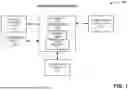


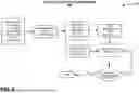


Sources:
- United States Patent and Trademark Office - verify current appl. status at the USPTO↗
Recent applications in this class:
- » 20250198634 2025-06-19
SYSTEM FOR MOBILE TERMINAL TO COMMUNICATE WITH PLURALITY OF HOT WATER SUPPLY DEVICES - » 20250137664 2025-05-01
HOT WATER SUPPLY SYSTEM - » 20240361007 2024-10-31
HOT WATER SUPPLY SYSTEM - » 20240328636 2024-10-03
ELECTRIC BOILER DEVICE BASED ON UTILIZATION OF RESIDUAL ENERGY OF ELEVATOR, AND CONTROL METHOD - » 20240159401 2024-05-16
HOT WATER SUPPLY APPARATUS AND METHOD OF CONTROLLING THE SAME - » 20240151408 2024-05-09
Load Based Hot Water Temperature Control - » 20240077212 2024-03-07
SYSTEMS AND METHODS FOR REDUCING CONDENSATION ON BUILDING WATER SUPPLY LINES - » 20230204226 2023-06-29
BOILER AND METHOD FOR STAGE CHANGE CONTROL THEREOF - » 20230184444 2023-06-15
Hot Water Recirculation System - » 20220381450 2022-12-01
Water heaters with real-time hot water supply determination