HEATING, VENTILATION, AND AIR CONDITIONING SYSTEM WITH FLEXIBLE ARRANGEMENTS
US20260043553A1
2026-02-12
18/799,951
2024-08-09
Smart Summary: A new HVAC system is designed to manage heating, ventilation, and air conditioning in different areas. It has multiple intake vents to bring air in and exhaust vents to send air out for a specific zone. A control module allows users to switch between heating, cooling, ventilation, and dehumidification modes. Air is taken from various zones, treated to the desired temperature or humidity, and then released back into the designated area. This flexible arrangement helps maintain comfort in different spaces efficiently. 🚀 TL;DR
Abstract:
A Heating, Ventilation, and Air Conditioning (HVAC) system. The HVAC system includes a plurality of intake vent assemblies configured for a first zone of a plurality of zones; a plurality of exhaust vent assemblies configured for the first zone of the plurality of zones; and a control module, the control module configured to control a heating mode, a ventilation mode, a dehumidification mode, and a cooling mode. For each of the heating, ventilation, dehumidification, and cooling modes, air is pulled from at least one of the plurality of zones into the HVAC system through at least one of the plurality of intake vent assemblies and conditioned by the HVAC system, and the air is supplied to the first zone through at least one of the plurality of exhaust vent assembly.
Inventors:
- Daniel Yu Hsu 11 🇺🇸 Upland, CA, United States
- Jimmy Liu 10 🇺🇸 Brea, CA, United States
- Wilbur Y. Cheng 10 🇺🇸 Chino Hills, CA, United States
- Wei Ying Shao 9 🇺🇸 Alhambra, CA, United States
Assignee:
- AC Infinity Inc. 2 🇺🇸 Walnut, CA, United States
Applicant:
Interested in similar patents?
Get notified when new applications in this technology area are published.
Classification:
F24F1/028 » CPC main
Room units for air-conditioning, e.g. separate or self-contained units or units receiving primary air from a central station; Self-contained room units for air-conditioning, i.e. with all apparatus for treatment installed in a common casing characterised by air supply means, e.g. fan casings, internal dampers or ducts
F24F11/74 » CPC further
Control or safety arrangements; Control systems characterised by their outputs; Constructional details thereof for controlling the supply of treated air, e.g. its pressure for controlling air flow rate or air velocity
Description
FIELD OF THE DISCLOSURE
The present application relates to the field of environmental engineering, particularly in the area of energy-saving and emission reduction consumer electronic products. More specifically, the present application relates to various types of Heating, Ventilation, and Air Conditioning (HVAC) systems with flexible arrangements.
BACKGROUND
An HVAC system, which stands for Heating, Ventilation, and Air Conditioning, is essential for creating comfortable and controlled environments across a range of settings. These systems are prevalent in residential, commercial, and industrial buildings, as well as in transportation, where they manage air temperature, humidity, airflow, and overall air quality. The benefits of HVAC systems are manifold. They elevate comfort levels by providing accurate temperature regulation and sustaining ideal humidity. Furthermore, they enhance air quality by filtering and purifying the air, thereby diminishing the presence of allergens, pollutants, and other contaminants that could adversely affect the health of the occupants.
However, there are some challenges associated with HVAC systems. The initial investment for installation can be substantial, particularly for larger or more intricate structures. This cost includes the price of the equipment, ductwork, control systems, and the labor required for the installation process. Additionally, these systems necessitate routine maintenance to maintain their peak performance and extend their lifespan. This involves the periodic cleaning or replacement of filters, air conduits, and other components. The complexity of HVAC systems often means that professional knowledge is required for their installation, troubleshooting, and repair. Moreover, their operation, particularly in large spaces is energy-intensive, demands a substantial amount of electricity, which significantly contributes to carbon emissions, leaving a considerable environmental footprint.
SUMMARY OF THE INVENTION
According to a first aspect of the present disclosure, a heating, ventilation, and air conditioning (HVAC) system is provided. The HVAC system includes a plurality of intake vent assemblies configured for a first zone of a plurality of zones; a plurality of exhaust vent assemblies configured for the first zone of the plurality of zones; and a control module, the control module configured to control a heating mode, a ventilation mode, a dehumidification mode, and a cooling mode; where for each of the heating, ventilation, dehumidification, and cooling modes, air is pulled from at least one of the plurality of zones into the HVAC system through at least one of the plurality of intake vent assemblies and conditioned by the HVAC system, and the air is supplied to the first zone through at least one of the plurality of exhaust vent assemblies.
According to a second aspect of the present disclosure, a portable heating, ventilation, and air conditioning (HVAC) system is provided. The portable HVAC system includes a temperature-humidity sensor configured to detect environmental information of a first zone; a housing accommodating internal components of the portable HVAC system, with a replaceable heat exhaust duct adapter and a replaceable cool exhaust duct adapter, the internal components within the housing including a power unit for connecting to electric power; an I/O interface configured for receiving control input information and outputting status output information; an air conditioning unit including an evaporator and a condenser, the evaporator connected to the evaporator duct adapter and the condenser connected to the condenser duct adapter; a fan configured to circulate air conditioned by the portable HVAC system to the first zone in response to a fan control signal; and a controller connected to the temperature-humidity sensor, the power unit, the I/O interface, the air conditioning unit, and the fan, the controller is configured to generate the fan control signal based on the control input information and the environmental information and to provide the status output information for outputting by the I/O interface, where the portable HVAC system is transportable when operating in at least one of a heating mode, a ventilation mode, a dehumidification mode, and a cooling mode.
According to a third aspect of the present disclosure, a portable heating, ventilation, and air conditioning (HVAC) system is provided. The portable HVAC system includes a top cover, a chassis, and enclosure walls on front, rear, left, and right sides of the portable HVAC system, with openings provided on the enclosure walls to allow for air entry into and exit from the portable HVAC system; an air conditioning unit including an evaporator and a condenser, a control panel with a display screen on the top cover for displaying real-time status information of a zone of interest where air-conditioning is needed; a control module connected to the control panel with a user interface for receiving input of desired settings; a fan module including at least one fan for circulating air conditioned by the portable HVAC system to the zone of interest; and a sensing module including a temperature-humidity sensor for sensing an environmental temperature value TENV and an environmental relative humidity value RHENV in the zone of interest, where vapor pressure deficiency (VPD) value of objects located in the zone of interest is calculated based thereon; where the control module generates and transmits a control signal to the fan module based at least in part on the VPD value of the indoor plants and the input of desired settings, and where each of the openings is compatible with both a shutter coupler and a duct adapter to facilitate co-location and separation of the portable HVAC system and the zone of interest.
It should be understood that all combinations of the foregoing concepts and additional concepts described in greater detail herein are contemplated as being part of the subject matter disclosed herein. For example, all combinations of claimed subject matter appearing at the end of this disclosure are contemplated as being part of the subject matter disclosed herein.
This Summary is provided to introduce a selection of concepts in a simplified form that are further described below in the Detailed Description. This Summary is not intended to identify key features or essential features of the claimed subject matter, nor is it intended to be used to limit the scope of the claimed subject matter. All of the above-outlined features are to be understood as exemplary only, and many more features and objectives of the various embodiments may be gleaned from the disclosure herein. Therefore, no limiting interpretation of this summary is to be understood without further review of the entire specification, claims, and drawings included herewith. A more extensive presentation of features, details, utilities, and advantages of the present disclosure is provided in the following written description of various embodiments of the disclosure, illustrated in the accompanying drawings, and defined in the appended claims.
BRIEF DESCRIPTION OF THE DRAWINGS
To provide a clearer representation of the concepts and innovations presented in the present disclosure, the accompanying drawings, which will be elaborated upon in the Detailed Description, will be briefly introduced first. It is important to note that the drawings provided are merely illustrative of selected embodiments of the present disclosure and are by no means exhaustive. A person of ordinary skill in the art may derive additional figures from these without engaging in inventive effort. A comprehensive understanding of the embodiments of the present disclosure will be gained from the subsequent Detailed Description, in conjunction with the drawings, where:
FIG. 1A illustrates a schematic perspective view of an HVAC system according to an exemplary embodiment of the present disclosure.
FIG. 1B illustrates a schematic perspective view of an HVAC system according to an exemplary embodiment of the present disclosure.
FIG. 2 illustrates a schematic front view of an HVAC system according to an exemplary embodiment of the present disclosure.
FIG. 3A illustrates a schematic front view of an HVAC system operating in a first mode according to an exemplary embodiment of the present disclosure.
FIG. 3B illustrates a schematic front view of an HVAC system operating in a second mode according to an exemplary embodiment of the present disclosure.
FIG. 3C illustrates a schematic front view of an HVAC system operating in a third mode according to an exemplary embodiment of the present disclosure.
FIG. 4 illustrates a schematic simplified block diagram of a portable HVAC system according to an exemplary embodiment of the present disclosure.
FIGS. 5A and 5B illustrate schematic views of a partial assembly of an HVAC system according to an exemplary embodiment of the present disclosure.
FIGS. 6A and 6B illustrate schematic views of a partial assembly of an HVAC system according to an exemplary embodiment of the present disclosure.
FIGS. 7A to 7C illustrate schematic views of a partial assembly of an HVAC system according to an exemplary embodiment of the present disclosure.
FIGS. 8A and 8B illustrate schematic front views of a first flexible arrangement of an HVAC system's ductwork relative to a chamber and its variants according to an exemplary embodiment of the present disclosure.
FIGS. 9A and 9B illustrate schematic front views of a second flexible arrangement of an HVAC system's ductwork relative to a chamber and its variants according to an exemplary embodiment of the present disclosure.
FIGS. 10A and 10B illustrate schematic front views of a third flexible arrangement of an HVAC system's ductwork relative to a chamber and its variants according to an exemplary embodiment of the present disclosure.
FIG. 11 illustrates a schematic simplified block diagram of a portable HVAC system according to an exemplary embodiment of the present disclosure.
FIGS. 12A and 12B illustrate schematic views of a partial assembly of an HVAC system according to an exemplary embodiment of the present disclosure.
FIGS. 13A and 13B illustrate schematic views of a partial assembly of an HVAC system according to an exemplary embodiment of the present disclosure.
FIG. 14 illustrates a simplified block diagram of an HVAC system according to an exemplary embodiment of the present disclosure.
FIG. 15 illustrates a schematic view of an exemplary user interface according to an exemplary embodiment of the present disclosure.
It is understood that, for the sake of simplicity and clarity, the elements depicted in the figures may not be necessarily depicted to scale. For instance, certain elements may be disproportionately sized relative to others to enhance clarity. Additionally, the same reference numerals may be used across the figures to denote corresponding or similar elements, where appropriate.
DETAILED DESCRIPTION
In the growing industry of indoor cannabis cultivation, the need for sophisticated environmental control systems has become increasingly apparent. The legalization of cannabis cultivation for personal use in various regions has spurred a demand for portable and adaptable solutions that can cater to specific needs of this specialized market. Traditional methods, however, fall short in addressing various requirements of indoor grow spaces.
Existing technology often employs a one-size-fits-all approach, attempting to control the environment of the entire room in which a grow space is located. Although this method is somewhat effective, it does not provide precise conditions necessary for optimal cannabis growth. It results in inefficient resource utilization, as the entire room's environment is modified to meet the needs of a relatively small grow space. This compromises both the comfort of the living space and fails to provide the necessary precision control within the grow space such as a grow tent or a cultivation chamber where cannabis plants or any other types of high-value plants are cultivated.
Another common practice involves placing an environmental control unit directly inside the grow space. While this method offers more localized control, it introduces its own set of challenges. The physical presence of the control unit within the grow space takes up valuable area that could otherwise be utilized for plant cultivation. This reduces the overall efficiency and capacity of the grow space, making it less practical for individuals with limited indoor space.
Of course, the plant cultivation mentioned above is just one example among numerous use cases that require precise air conditioning and handling. Other scenarios include controlled environment agriculture optimizing growth for specific crops, laboratories and research facilities needing stable conditions for experiments, data centers maintaining equipment temperatures, hospitals ensuring sterile environments for patient care, museums preserving artifacts with climate control, greenhouses creating ideal growing conditions, industrial processes sensitive to environmental changes, commercial kitchens managing heat and odors, and both commercial and residential buildings conserving energy while ensuring occupant comfort, among others. These diverse applications underscore the significance of versatile and advanced HVAC systems that can cater to an array of environments and needs, with the capability to finely control and monitor air quality, temperature, and humidity being essential for operational success and the well-being of the occupants.
The inventors of the present disclosure have observed the shortcomings of existing practices and urgent needs for improved HVAC systems applicable across various domains. Recognizing the necessity for a more nuanced and efficient approach, they have developed innovative HVAC systems that directly address these challenges. These systems are specifically designed to provide targeted environmental control within the grow space, while minimizing the impact on the surrounding living space and maximizing the efficiency of air control. This is especially critical considering the distinct environmental zones that must be managed in an indoor grow setup with the proposed HVAC systems, namely the outdoor and indoor environment with respect to the grow space, and the grow space itself. Each of these zones has its own unique set of environmental parameters that has to be accurately balanced to maximize air control efficiency, reduce power consumption, and ensure the overall health and growth of the cannabis plants.
Now referring to FIGS. 1A and 1B, which illustrate schematic perspective views of an HVAC system 100 according to an exemplary embodiment of the present disclosure. The HVAC system 100 may include at least one intake vent assembly 110 configured to pull air into the HVAC system 100 and at least one exhaust vent assembly 120 configured to supply air conditioned by the HVAC system 100. The air pulled into the HVAC system 100 through the at least one intake vent assembly 110 may come from an outdoor and/or an indoor environment with respect to a grow space such as a grow tent or a cultivation chamber, or the grow space itself, depending on the application scenario of the HVAC system (e.g., the selected mode of HVAC system, temperature and/or humidity requirements of a target environment), the purposes of air treatment, and energy-saving needs (e.g., electricity consumption requirements), etc. Similarly, air conditioned by the HVAC system 100 and supplied through the at least one exhaust vent assembly 120 may be expelled to the outdoor and/or indoor environment with respect to the grow space, or the grow space itself, depending on more or less the same factors as described above.
As used herein, the term target environment may refer to a space in which its temperature, (relative) humidity or any other air-related indicator (e.g., airflow velocity, air quality, pressure), or a combination thereof needs to be adjusted. Note that the target environment may coincide with the grow space in some contexts, but not necessarily. The target environment may also refer to other spaces or areas outside of the grow space.
By way of example and not limitation, under a condition that a cooling mode or a heating mode of the HVAC system is selected, air may be pulled from the outdoor environment with respect to the grow space into the HVAC system 100 through the at least one intake vent assembly 110. Subsequent to the treatment by the HVAC system 100, air conditioned by (e.g., treated, processed or passed through) the HVAC system 100 may be supplied (e.g., expelled from the HVAC system 100) to the grow space whose temperature needs to be lowered or raised through the at least one exhaust vent assembly 120. Note that the outdoor environment and the grow space may be interchanged, under which case the term target environment may refer to the outdoor environment rather than the grow space itself. Similarly, the target environment may also refer to the indoor environment where the grow space is situated.
By way of example and not limitation, under a condition that the grow space itself has a temperature and/or a humidity that is closer to that of the indoor environment where it is located than to that of the outdoor environment, and that the adjustment required for a desired temperature and/or humidity within the grow space is relatively minor, air may be pulled from the indoor environment with respect to the grow space into the HVAC system 100 through the at least one intake vent assembly 110. Then, following the treatment by the HVAC system 100, the conditioned air may be supplied through the at least one exhaust vent assembly 120 to the grow space whose temperature and/or humidity needs to be adjusted to the desired one(s). As such, the demand for energy saving and emission reduction is met while achieving temperature and/or humidity regulation.
Although FIGS. 1A and 1B depict two intake vent assemblies and two exhaust vent assemblies for illustrative purposes, it is to be understood that the HVAC system 100 may include any desired number of each type of vent assembly and that the number of the intake vent assemblies and the number of the exhaust vent assemblies do not have to be identical. This means that air may be pulled into the HVAC system 100 through more than one intake vent assemblies, and/or air conditioned by the HVAC system 100 may be supplied through more than one exhaust vent assemblies. Consequently, air pulled into the HVAC system 100 through the more than one intake vent assemblies may come from different areas or spaces which may include the grow space itself, because each of the intake vent assemblies may be coupled with a duct directed to a specific area or space, with the ducts of any two of the intake vent assemblies not being necessarily directed to a same area or space. Likewise, air conditioned by the HVAC system 100 and supplied through the more than one exhaust vent assemblies may be expelled to different areas or spaces which may include the grow space itself, because each of the exhaust vent assemblies may be coupled with a duct directed to a specific area or space, with the ducts of any two of the exhaust vent assemblies not being necessarily directed to a same area or space. This implies that assuming the grow space is the target environment, the conditioned air may also be supplied to other area(s) or space(s) besides the grow space itself. In other words, when reference is made to a target environment, it may refer to more than one area or space.
As such, compared to the conventional HVAC systems with a relatively fixed and single-purpose arrangement of intake vent assembly and exhaust vent assembly, the flexible arrangement of intake vent assembly and exhaust vent assembly in the HVAC system proposed by the present disclosure enables its application in various environmental settings that require precise and differentiated air regulation for multiple relatively independent zones. This allows users to readily and flexibly choose where the air intake comes from and where the air exhaust goes, thus achieving fine control of environmental parameters in multiple zones while effectively reducing energy consumption and carbon emissions.
The above is merely an illustrative and non-exhaustive explanation of the number and arrangement of each type of vent assembly (i.e., the at least one intake vent assembly 110 and the at least one exhaust vent assembly 120) in the HVAC system 100 as shown in FIGS. 1A and 1B, and it should be apparent to a person of ordinary skill in the art that any other suitable modifications, replacements, and/or variants are possible and fall within the scope of the present disclosure.
For the sake of simplicity, the following sections primarily illustrate the inventive concepts of the present disclosure by taking an example in which an HVAC system configured with two intake vent assemblies and two exhaust vent assemblies as well as one cultivation chamber designated as the target environment are deployed. Of course, this does not preclude the possibility that the inventive concepts of the present disclosure could be embodied in an HVAC system with other suitable numbers of intake vent assemblies and exhaust vent assemblies, which should be apparent to a person of ordinary skill in the art.
FIG. 2 illustrates a schematic front view of an HVAC system 100 according to an exemplary embodiment of the present disclosure. The HVAC system 100 may include a plurality of intake vent assemblies and a plurality of exhaust vent assemblies. By way of example and not limitation, the intake vent assemblies may include a first intake vent C 1101 and a second intake vent D 1102, and the exhaust vent assemblies may include a first exhaust vent A 1201 and a second exhaust vent B 1202. Referring to FIG. 2 in conjunction with FIGS. 1A and 1B, it can be readily seen that the second exhaust vent B 1202 takes the form of shutters, and both the first intake vent C 1101 and the second intake vent D 1102 take the form of adapters with couplers. It should be understood that the shutters of the second exhaust vent B 1202 can be replaced with duct adapters, for example. Additionally or alternatively, the first exhaust vent A 1201 may also take the form of shutters. Similarly, the couplers of the first intake vent C 1101 and the second intake vent D 1102 can each be interfaced with ductwork. This facilitates the guidance of air from specific areas to the HVAC system 100 or the guidance of conditioned air from the HVAC system 100 to specific target environments.
FIG. 3A illustrates a schematic front view of an HVAC system 100 operating in a first mode according to an exemplary embodiment of the present disclosure. In some embodiments, the HVAC system 100 may include a sensing module connected to a control module of the HVAC system 100 and configured to detect at least one of an environment temperature value, an environment vapor pressure deficiency (VPD) value, and an environment relative humidity value of a target environment 210 that occupies a cultivation chamber 200. In some embodiments, the control module, which is not explicitly shown in the figure, may be configured to control a heating mode, a ventilation mode, a dehumidification mode, and a cooling mode of the HVAC system 100. In some embodiments, under a condition that the target environment includes only a single area or space, such as the cultivation chamber 200 as shown in the figure, the sensing module may include a sensor probe which could be placed within the target environment for collecting various pertinent environmental readings with respect to the target environment. In some embodiments, under a condition that the target environment includes more than one single area or space, the sensing module may include a set of sensor probes which could be placed within respective areas or spaces, with each of which collecting various pertinent environmental readings with respect to a specific one of the respective areas or spaces. In some embodiments, the readings collected or sensed by the sensor probe may be transmitted to the control module for further processing either by wire or wirelessly.
In some embodiments, the readings may include but not limited to an environment temperature value, an environment VPD value, an environment relative humidity value, airflow velocity, air quality, pressure, etc.
Referring to FIG. 3A in conjunction with FIG. 2, the first intake vent C 1101 and the second intake vent D 1102 may be connected to a heating chamber and a cooling chamber of the HVAC system 100, respectively, and the first exhaust vent A 1201 and the second exhaust vent B 1202 may be connected to the heating chamber and the cooling chamber, respectively. In some embodiments, the heating chamber, which is not shown in the figure, may include a condenser, a compressor, fans, insulation materials, etc., as would be readily appreciated by a person of ordinary skill in the art, which is thus not further elaborated herein. In some embodiments, the cooling chamber, which is not shown in the figure, may include an evaporator, refrigerant lines, fans, drainage, insulation materials, etc., as would be readily appreciated by a person of ordinary skill in the art, which is thus not further elaborated herein. In some embodiments, the first mode may be the heating mode of the HVAC system 100. In such case, when the control module determines that the environment temperature value, for example, that is obtained from the sensor probe is less than a predetermined temperature value and/or the environment vapor pressure deficiency (VPD) value, for example, that is obtained from the sensor probe is less than a predetermined VPD value, the air conditioned by the HVAC system 100 may be supplied to the target environment such as the cultivation chamber 200 through the first exhaust vent A 1201.
In some embodiments, predetermined settings of the target environment may be received via an Input/Output (I/O) interface which may be integral to or separate from the HVAC system 100. In some embodiments, the I/O interface, which is not explicitly shown in the figure, may be configured to facilitate interactions with users of the HVAC system 100, for example, by providing controls for receiving user inputs, outputting real-time environmental readings of the target environment to users visually or acoustically, and the like. In some embodiments, the predetermined settings may include but not limited to at least one of the predetermined temperature value, the predetermined VPD value, a predetermined relative humidity value, a predetermined airflow velocity, a predetermined air quality, a predetermined pressure of the target environment.
Continuing to refer to FIG. 3A, a duct may be extended from the first exhaust vent A 1201 into the cultivation chamber 200, with one end of which connecting to a duct adapter and another end of which disposed inside the cultivation chamber 200, possibly through hermetic aperture. In some embodiments, the second exhaust vent B 1202 may expel air that has been treated to a relatively lower temperature, for example, by discharging it directly into the indoor environment where the cultivation chamber 200 is located, as shown in the figure, or by discharging it to an outdoor environment with respect to the cultivation chamber 200, for example, through a duct connecting to a duct adapter in lieu of the shutter mounted at the second exhaust vent B 1202. In some embodiments, under a condition that the HVAC system 100 operates in the heating mode, air may be pulled into the HVAC system 100 through either or both of the first intake vent C 1101 and the second intake vent D 1102. Optionally, the coupler of the adapter of either of both of the first intake vent C 1101 and the second intake vent D 1102 may be connected with a duct for directing to the HVAC system 100 air from area or space away from the place where the HVAC system 100 locates, for example, the outdoor environment with respect to the cultivation chamber 200.
Now referring to FIG. 3B where a schematic front view of an HVAC system operating in a second mode according to an exemplary embodiment of the present disclosure is illustrated. In some embodiments, the second mode may be a cooling mode of the HVAC system 100. In such case, when the control module determines that the environment temperature value, for example, that is obtained from the sensor probe is greater than a predetermined temperature value and/or the environment VPD value, for example, that is obtained from the sensor probe is greater than a predetermined VPD value, the air conditioned by the HVAC system 100 may be supplied to the target environment such as the cultivation chamber 200 through the second exhaust vent B 1202.
Continuing to refer to FIG. 3B, a duct may be extended from the second exhaust vent B 1202 into the cultivation chamber 200, with one end of which connecting to a duct adapter in lieu of the shutter that is otherwise mounted at the second exhaust vent B 1202 and another end of which disposed inside the cultivation chamber 200, possibly through hermetic aperture. In some embodiments, the first exhaust vent A 1201 may expel air that has been treated to a relatively higher temperature, for example, by discharging it directly into the indoor environment where the cultivation chamber 200 is located, as shown in the figure, or by discharging it to an outdoor environment with respect to the cultivation chamber 200, for example, through a duct connecting to a duct adapter. In some embodiments, under a condition that the HVAC system 100 operates in the cooling mode, air may be pulled into the HVAC system 100 through either or both of the first intake vent C 1101 and the second intake vent D 1102. Optionally, the coupler of the adapter of either of both of the first intake vent C 1101 and the second intake vent D 1102 may be connected with a duct for directing to the HVAC system 100 air from area or space away from the place where the HVAC system 100 locates, for example, the outdoor environment with respect to the cultivation chamber 200.
Referring to FIG. 3C where a schematic front view of an HVAC system operating in a third mode according to an exemplary embodiment of the present disclosure is illustrated. In some embodiments, the third mode may be a dehumidification mode of the HVAC system 100. In such case, when the control module determines that the environment relative humidity value, for example, that is obtained from the sensor probe is greater than a predetermined relative humidity value and/or the environment VPD value, for example, that is obtained from the sensor probe is less than a predetermined VPD value, the air conditioned by the HVAC system 100 may be supplied to the target environment such as the cultivation chamber 200 through the first exhaust vent A 1201 and the second exhaust vent B 1202.
In some embodiments, under a condition that the HVAC system 100 operates in the dehumidification mode, at least one of the first intake vent C 1101 and the second intake vent D 1102 may be connected to the target environment such as the cultivation chamber 200. Continuing to refer to FIG. 3C, a duct may be extended from the first intake vent C 1101 into the cultivation chamber 200, with one end of which connecting to the coupler of the adapter mounted at the first intake vent C 1101 and another end of which disposed inside the cultivation chamber 200, possibly through hermetic aperture. Additionally, or alternatively, a duct may be extended from the second intake vent D 1102 into the cultivation chamber 200, with one end of which connecting to the coupler of the adapter mounted at the second intake vent D 1102 and another end of which disposed inside the cultivation chamber 200, possibly through hermetic aperture.
It can be understood that in FIG. 3C, for illustrative purposes only, both the first intake vent C 1101 and the second intake vent D 1102 are shown to be connected with ducts leading to the cultivation chamber 200. However, this is not necessary; it is sufficient for the HVAC system 100 to operate normally in dehumidification mode with just one of the vents, either the first intake vent C 1101 or the second intake vent D 1102, being connected with a duct to the cultivation chamber 200, as described above.
It should be noted that the direction and layout of the various ducts shown in FIGS. 3A to 3C are merely illustrative and do not constitute any limitation on the present disclosure.
FIG. 4 illustrates a schematic simplified block diagram of a portable HVAC system 400 for indoor plant cultivation according to an exemplary embodiment of the present disclosure. As shown in FIG. 4, the portable HVAC system 400 may include temperature-humidity sensor 401. In some embodiments, the temperature-humidity sensor 401 may be configured to detect environmental information of a target environment, for example, for indoor plants cultivation. By way of example and not limitation, the environmental information may include an environment temperature value, an environment VPD value, an environment relative humidity value, airflow velocity, air quality, pressure, etc. of the target environment. In some embodiments, the target environment may also refer to as a first zone among a plurality of zones where the objects such as indoor plants are grown or cultivated, for example, a grow tent, a cultivation chamber, and the like. The plurality of zones may include at least one indoor area or space and at least one outdoor area or space with respect to the target environment. It should be noted that the indoor plants may include not only high-value crops but also any other suitable types of plants that are sensitive to changes in environmental parameters, and the present disclosure does not impose any restrictions on that. In some embodiments, the temperature-humidity sensor 401 may be separable from a body of the portable HVAC system 400. In such case, the environment information detected by the temperature-humidity sensor 401 may be transmitted from the sensor to the HVAC system 400, for example, to the controller as described hereinafter either by wire or wirelessly.
As shown in FIG. 4, the portable HVAC system 400 may include a housing 402. The housing 402 may be referred to as the body of the portable HVAC system 400 and may be configured to accommodate internal components of the portable HVAC system 400. In some embodiments, the housing 402 may be configured with a replaceable heat exhaust duct adapter 4021 and a replaceable cool exhaust duct adapter 4022. In some embodiments, the replaceable heat exhaust duct adapter 4021 and a replaceable cool exhaust duct adapter 4022 may each be provided on a surface of the housing 402.
In some embodiments, the replaceable heat exhaust duct adapter 4021 may be configured to allow air that has been conditioned by the portable HVAC system 400, and which has a relatively high temperature compared to the intake air, to pass through. In some embodiments, the replaceable heat exhaust duct adapter 4021 may be configured to directly connect to a duct directing the conditioned air through the duct to areas or spaces that require an increase in temperature.
In some embodiments, the replaceable cool exhaust duct adapter 4022 may be configured to allow air that has been conditioned by the portable HVAC system 400, and which has a relatively low temperature compared to the intake air, to pass through. In some embodiments, the replaceable cool exhaust duct adapter 4022 may be configured to directly connect to a duct, directing the conditioned air through the duct to areas or spaces that require a decrease in temperature.
As shown in FIG. 4, the internal components of the portable HVAC system 400 may include but not limited to a power unit 403, an I/O interface 404, an air conditioning unit 405, a fan 406, and a controller 407. In some embodiments, the power unit 403 may be configured to connect to electric power, manage power supply of the portable HVAC system 400, and provide backup power in case of a power outage. In some embodiments, the I/O interface 404 may be configured to receive control input information and output status output information.
In some embodiments, the control input information may be manually input by a user of the portable HVAC system 400, for example, a touch input or a series of touch inputs physically provided by the user on-site, or control instruction(s) provided by the user away from the portable HVAC system 400, e.g., via an app or applet installed on the user's mobile terminal. In some embodiments, the control input information may be input by a central controller which is configured to manage several HVAC systems, each associated with a respective target environment, including the portable HVAC system 400. In some embodiments, the central controller may be separate from the portable HVAC system 400, i.e., an external controller. By doing so, users of the portable HVAC system 400 can power and program all areas or spaces of interest, such as their grow tents or cultivation chambers, either collectively for unified control or individually for optimized environmental management tailored to each area or space. In some embodiments, the control input information may be pertinent to environment settings of the target environment, such as an environment temperature value, an environment VPD value, an environment relative humidity value, airflow velocity, air quality, pressure, etc. of the first zone. In some embodiments, the control input information may also include pieces of information that are pertinent to operational settings of the portable HVAC system 400, such as a count-down, a Min level and a Max level of the fan 406, a mode selection, and the like.
In some embodiments, the status output information may include, but is not limited to: the current mode of the portable HVAC system 400; a trend indicator signaling whether the setting is rising, falling, or holding steady; a probe temperature indicating the current temperature detected within the first zone; a probe VPD indicating the current VPD detected within the first zone; a probe humidity indicating the current humidity detected within the first zone; alert messages displaying alerts and statuses of the portable HVAC system 400; and other relevant data.
In some embodiments, the air conditioning unit 405 may include an evaporator 4051 and a condenser 4052. In some embodiments, the evaporator 4051 may be connected to (i.e., coupled with) an evaporator duct adapter 4053 and/or the condenser 4052 may be connected to (i.e., coupled with) a condenser duct adapter 4054.
Now referring to FIGS. 5A and 5B, FIGS. 5A and 5B illustrate schematic views of a partial assembly of an HVAC system according to an exemplary embodiment of the present disclosure. By way of example and limitation, the HVAC system may be the portable HVAC system 400. In some embodiments, the evaporator duct adapter 4053 may be mounted—using a snap fit mechanism, for example—on an upper vent of the portable HVAC system 400, which is known as the ‘cold air entry’. Specifically, a user of the portable HVAC system 400 may insert flat fasteners at the front of the evaporator duct adapter 4053 into corresponding openings provided on the periphery of the upper vent, as shown in FIG. 5A. Once the front end of the evaporator duct adapter 4053 is attached, the user may squeeze the back end towards the front, and then push in until hearing clips click into place, as shown in FIG. 5B. In some embodiments, the evaporator duct adapter 4053 may be removed for periodic maintenance. Note that the replaceable heat exhaust duct adapter 4021 is also visible in FIGS. 5A and 5B, while the replaceable cool exhaust duct adapter 4022, which is disposed opposite to it, for example, is not visible in the figures due to the viewing angle.
FIGS. 6A and 6B illustrate schematic views of a partial assembly of an HVAC system according to an exemplary embodiment of the present disclosure. By way of example and limitation, the HVAC system may be the portable HVAC system 400. In some embodiments, as shown in FIG. 6A, the condenser duct adapter 4054 may be mounted—also using a snap fit mechanism, for example—on a bottom vent of the portable HVAC system 400, which is known as the ‘hot air entry’. It should be noted that the evaporator duct adapter 4053 and the condenser duct adapter 4054 are not necessary. Either of them may be used to achieve side air intake and dust prevention through a duct coupler 4059, and also may be coupled with ducting via the duct coupler 4059 to realize directional air intake (for example, to introduce air from a specific area or space), as shown in FIG. 6B. In some embodiments, as shown in FIG. 6B, a first few rings of ducting may be extended and screwed onto the duct coupler 4059 such that the evaporator duct adapter 4053 and/or the condenser duct adapter 4054 may be coupled with respective ducting.
FIGS. 7A to 7C illustrate schematic views of a partial assembly of an HVAC system according to an exemplary embodiment of the present disclosure. In some embodiments, either of the replaceable heat exhaust duct adapter 4021 and the replaceable cool exhaust duct adapter 4022 may be embodied by a shutter coupler for the purpose of side air exhaust and dust prevention, and may also be embodied by a duct adapter to connect to ducting, thereby achieving directional air exhaust (for example, guiding conditioned air to a specific area or space). As shown in FIG. 7A, a shutter coupler 4057 may initially act as the replaceable cool exhaust duct adapter 4022, for example, at the second exhaust vent B 1202 which is depicted in FIG. 2. Under a condition that the directional air exhaust is needed, the shutter coupler 4057 may be twisted and pulled off from the top vent. As shown in FIG. 7B, a ducting may be screwed onto a duct adapter 4058 which may take the form of a duct adapter base, for example. As shown in FIG. 7C, the duct adapter 4058 may then be screwed onto the top vent, transitioning its function from side air exhaust to directional air exhaust, allowing for more controlled air flow. It can be understood that the description here takes the second exhaust vent B 1202 shown in FIG. 2 as an example of the top vent, but the assembly process shown in FIGS. 7A to 7C can be applied to other top vents, such as the first exhaust vent A 1201, which is arranged opposite to the second exhaust vent B 1202 in FIG. 2.
Refer back to FIG. 4. In some embodiments, the fan 406 may be configured to circulate air conditioned by the portable HVAC system 400 to the first zone in response to a fan control signal.
In some embodiments, the controller 407 may be configured to connect to the temperature-humidity sensor 401, the power unit 403, the I/O interface 404, the air conditioning unit 405, and the fan 406. In some embodiments, the controller 407 may be configured to generate the fan control signal based on the control input information and the environmental information and to provide the status output information for outputting by the I/O interface 404.
In some embodiments, the portable HVAC system 400 may be transportable when operating in at least one of a heating mode, a ventilation mode, a dehumidification mode, and a cooling mode. By way of example and not limitation, the chassis of the portable HVAC system 400 may be configured with a set of universal wheels, sliding rails, or any other suitable mobile mechanism.
As such, the portable HVAC system 400 is designed to achieve a range of beneficial technical effects that make it a highly advantageous solution for environmental control. One of the key benefits is the elimination of the need to place the system itself directly inside the grow space. This innovative approach conserves valuable space within the grow space that would otherwise be occupied by the system, which is not only space-inefficient but also uneconomical. By externalizing the system, the area available for cultivation is maximized, thereby optimizing the use of the grow space.
Moreover, the system's design allows for greater flexibility and adaptability. As described above, the chassis of the portable HVAC system 400 may be equipped with a wheel assembly, a sliding rail, or any other suitable mobile mechanism, enhancing its mobility and ease of repositioning as needed. This portability and adaptability, free from the constraints of a fixed installation site, enhance the system's practicality and convenience. The result is a more streamlined setup process, reduced costs and effort, and a more efficient environmental control solution for controlled environment agriculture. The system is particularly beneficial to grow spaces often crowded with plants, where installation and maintenance can be challenging.
The following will introduce several flexible arrangements of the ductwork for the portable HVAC system 400. It should be noted that referring to the various vents A to D shown in FIG. 2 will be helpful when reading about the various arrangements of the ductwork in FIGS. 8 to 10.
FIGS. 8A and 8B illustrate schematic front views of a first flexible arrangement of an HVAC system's ductwork relative to a cultivation chamber and its variants according to an exemplary embodiment of the present disclosure.
In the event of a negative pressure scenario, it arises when the volume of air being expelled exceeds that which is being drawn in. Such a configuration effectively precludes the mixing of internal air with the external environment, while simultaneously permitting external air to ingress into the grow tent. This feature is particularly advantageous for instances where the user seeks to prevent the escape of odors or airborne particles from the grow tent. It is important to observe that air within the grow tent will continue to be expelled through any exhaust ducts responsible for generating the negative pressure.
In some embodiments, as shown in FIG. 8A, the portable HVAC system may be located outside of the first zone, for example, the cultivation chamber 200, under a condition that the control input information indicates a negative pressure setting for the first zone and the cooling mode of the portable HVAC system, air in the first zone is exhausted through a first detachable ducting coupled to the evaporator duct adapter (indicated by D) and a second detachable ducting coupled to the condenser duct adapter (indicated by C), and the air conditioned by the portable HVAC system is supplied to the first zone through a third detachable ducting coupled to the cool exhaust duct adapter (indicated by B).
In some embodiments, as shown in FIG. 8B, the portable HVAC system is located outside of the first zone, under a condition that the control input information indicates a negative pressure setting for the first zone and the heating mode of the portable HVAC system: air in the first zone is exhausted through a first detachable ducting to the evaporator duct adapter (indicated by D) and a second detachable ducting coupled to the condenser duct adapter (indicated by C), and the air conditioned by the portable HVAC system is supplied to the first zone through a fourth detachable ducting coupled to the heat exhaust duct adapter (indicated by A).
FIGS. 9A and 9B illustrate schematic front views of a second flexible arrangement of an HVAC system's ductwork relative to a cultivation chamber and its variants according to an exemplary embodiment of the present disclosure.
In the event of a positive pressure scenario, it arises when there is more air coming in than being pushed out. This feature is particularly advantageous for preventing outside particles from entering the grow tent, but will allow the air inside to escape. This is useful for when users want full control of the air coming from into the grow tent.
In some embodiments, as shown in FIG. 9A, the portable HVAC system is located outside of the first zone, under a condition that the control input information indicates a positive pressure setting for the first zone and the cooling mode of the portable HVAC system: air conditioned by the portable HVAC system is supplied to the first zone through a third detachable ducting coupled to the cool exhaust duct adapter (indicated by B), and air outside of the first zone enters the portable HVAC system through an upper vent on which the evaporator duct adapter is mounted (indicated by D) and a bottom vent on which the condenser duct adapter is mounted (indicated by C).
In some embodiments, as shown in FIG. 9B, the portable HVAC system is located outside of the first zone, under a condition that the control input information indicates a positive pressure setting for the first zone and the heating mode of the portable HVAC system: air conditioned by the portable HVAC system is supplied to the first zone through a fourth detachable ducting coupled to the heat exhaust duct adapter (indicated by A), and air outside of the first zone enters the portable HVAC system through an upper vent on which the evaporator duct adapter is mounted (indicated by D) and a bottom vent on which the condenser duct adapter is mounted (indicated by C).
FIGS. 10A and 10B illustrate schematic front views of a third flexible arrangement of an HVAC system's ductwork relative to a cultivation chamber and its variants according to an exemplary embodiment of the present disclosure.
Neutral pressure occurs when the amount of air being pushed out is relatively equal to the amount of air blowing in. This creates a setup where very little air is exchanged between the grow tent and the outside environment. In some embodiments, as shown in FIG. 10A, the portable HVAC system is located outside of the first zone, under a condition that the control input information indicates a neutral pressure setting for the first zone and the cooling mode of the portable HVAC system: air in the first zone is exhausted through a first detachable ducting coupled to the evaporator duct adapter (indicated by D), and the air conditioned by the portable HVAC system is supplied to the first zone through a third detachable ducting coupled to the cool exhaust duct adapter (indicated by B), and air outside of the first zone enters the portable HVAC system through a bottom vent on which the condenser duct adapter is mounted (indicated by C).
In some embodiments, as shown in FIG. 10B, the portable HVAC system is located outside of the first zone, under a condition that the control input information indicates a neutral pressure setting for the first zone and the heating mode of the portable HVAC system: air in the first zone is exhausted through a second detachable ducting coupled to the condenser duct adapter (indicated by C), and the air conditioned by the portable HVAC system is supplied to the first zone through a fourth detachable ducting coupled to the heat exhaust duct adapter (indicated by A), and air outside of the first zone enters the portable HVAC system through an upper vent on which the evaporator duct adapter is mounted (indicated by D).
In some embodiments, the control input information includes a Min level and a Max level for a specified mode among the at least heating, ventilation, dehumidification, and cooling modes, and in response to a determination that the environmental information differs from the control input information for the specified mode by a first predetermined amount or quantity, the fan control signal is configured to cause the fan to gradually ramp up to the Max level. In some embodiments, the MIN level and/or the MAX level may be configured by user or set by default.
In some embodiments, the control input information includes a Min level and a Max level for a specified mode among the at least heating, ventilation, dehumidification, and cooling modes, and in response to a determination that the environmental information differs from the control input information for the specified mode by a second predetermined amount or quantity, the fan control signal is configured to cause the fan to gradually slow down to the Min level. In some embodiments, the MIN level and/or the MAX level may be configured by user or set by default. It can be readily appreciated that the first predetermined amount or quantity is greater than the second predetermined amount or quantity in the sense that the fan of the HVAC system is driven at a relatively higher rate if the temperature is greater than the designated temperature set by the user when operating in a cooling mode, for example.
FIG. 11 illustrates a schematic simplified block diagram of a portable HVAC system 1100, for example, for indoor plant cultivation according to an exemplary embodiment of the present disclosure.
The portable HVAC system 1100 may include a top cover 1101; a chassis 1102; enclosure walls 1103 on front, rear, left, and right sides of the portable HVAC system 1100, with openings 1104 provided on the enclosure walls to allow for air entry into and exit from the portable HVAC system 1100; an air conditioning unit 1105 including an evaporator 1105-1 and a condenser 1105-2; a control panel 1108 with a display screen 1108-2 on the top cover 1101 for displaying real-time status information of a zone of interest where indoor plants are cultivated; a control module 1107 connected to the control panel 1108 with a user interface 1108-1 for receiving input of desired settings; a fan module 1106 including at least one fan for circulating air conditioned by the portable HVAC system 1100 to the zone of interest; and a sensing module 1110 including a temperature-humidity sensor for sensing an environmental temperature value TENV and an environmental relative humidity value RHENV in the zone of interest, wherein vapor pressure deficiency (VPD) value of the indoor plants is calculated based thereon.
In some embodiments, the control module 1107 generates and transmits a control signal to the fan module 1106 based at least in part on the VPD value of the indoor plants and the input of desired settings, and each of the openings is compatible with both a shutter coupler and a duct adapter to facilitate co-location and separation of the portable HVAC system 1100 and the zone of interest.
FIGS. 12A and 12B illustrate schematic views of a partial assembly of an HVAC system according to an exemplary embodiment of the present disclosure.
As shown in FIGS. 12A and 12B, the HVAC system 1100 may further include a drainage hole 1290 for connecting with a drain pipe. In some embodiments, the HVAC system 1100 may be configured with a condensation tank inside the enclosure walls that collects water and thus needs to be drained as needed, for example, when the condensation tank is full. In some embodiments, the drainage hole 1290 may be provided on one of the enclosure walls of the HVAC system 1100, such as shown in FIG. 12A. In some embodiments, the drainage hole 1290 may be configured to connect to a drain pipe when it is not plugged by a drain cap, for example, when the drain cap is removed from the drainage hole 1290. In some cases, the drainage hole 1290 may be useful, especially when the zone of interest being air-conditioned needs to reduce environmental humidity. By connecting a drain pipe to the drainage hole 1290, cooled water stored in the condensation tank may be directed away from an intake area or space of the HVAC system 1100 where the air is drawn in. This prevents a potentially adverse effect of the intake area or space on the efficiency of air-conditioning of the zone of interest by the HVAC system 1100, which is usually ignored by conventional solutions. In some embodiments, the drainage hole 1290 may be used in conjunction with or in lieu of a drain 1295 that is for example directed toward the bottom of the chassis as shown in FIG. 12B.
FIGS. 13A and 13B illustrate schematic views of a partial assembly of an HVAC system according to an exemplary embodiment of the present disclosure.
As shown in FIGS. 13A and 13B, the HVAC system 1100 may further include a window duct kit 1390 for drawing in fresh air or expelling stale air. In some embodiments, the window duct kit 1390 may include one or more main plates, one or more track plates, bolts, nuts and additional fasteners required for assembly onto a window. In some embodiments, the assembly may be installed horizontally or vertically, depending on specific settings of the window. This provides an advantage of introducing fresh air from outside environment (e.g., outside of a living environment where users, the HVAC system and the zone of interest reside) into the zone of interest or expelling the stale air from the zone of interest outside of the living environment.
FIG. 14 illustrates a simplified block diagram of an HVAC system 1400 according to an exemplary embodiment of the present disclosure.
In some embodiments, the HVAC system 1400 may include a plurality of intake vent assemblies 1410 configured for a first zone of a plurality of zones; a plurality of exhaust vent assemblies 1420 configured for the first zone of the plurality of zones; and a control module 1430, the control module configured to control a heating mode, a ventilation mode, a dehumidification mode, and a cooling mode. According to embodiments of the present disclosure, for each of the heating, ventilation, dehumidification, and cooling modes, air is pulled from at least one of the plurality of zones into the HVAC system through at least one of the plurality of intake vent assemblies and conditioned by the HVAC system, and the air is supplied to the first zone through at least one of the plurality of exhaust vent assemblies.
By way of example and not limitation, the plurality of intake vent assemblies 1410 may each include the first intake vent C 1101 or the second intake vent D 1102 or a pair of both, depending on specific designs or usage cases. By way of example and not limitation, the plurality of exhaust vent assemblies 1420 may each include the first exhaust vent A 1201 or the second exhaust vent B 1202 or a pair of both, depending on specific designs or usage cases. Unlike conventional HVAC systems that offer a rigid and one-size-fits-all design for intake and exhaust vents, the HVAC system 1400 offers various arrangements that are particularly beneficial for usage cases requiring tailored air handling in one or more distinct zones. The proposed HVAC system 1400 enables users to make informed choices regarding the location of air inlets and outlets with flexibility. This leads to the efficient management of environmental conditions across different zones, while also promoting energy savings and lowering carbon emissions.
FIG. 15 illustrates a schematic view of an exemplary user interface according to an exemplary embodiment of the present disclosure. As shown in FIG. 15, an exemplary and non-limiting user interface is provided, which may include mode button 1, up/down buttons 2, unit button 3, setting button 4, probe temperature 5, probe VPD 6, probe humidity 7, controller mode 8, current level 9, user setting 10, countdown 11, alert icons 12, function mode 13, and vent status 14. The following describes the user interface shown in FIG. 15.
1. MODE BUTTON. This button may act as a central control button for the HVAC system/controller, managing various operational modes thereof and allowing users to cycle through. By pressing this button, one may switch between OFF, ON, AUTO, VPD, TIMER TO OFF, and CYCLE modes. The CYCLE mode may be particularly useful as it may alternate between ON and OFF, providing a customizable on-and-off cycling schedule for enhanced comfort and energy efficiency.
2. UP/DOWN BUTTONS. These buttons may be used to adjust the intensity or value of the current mode selected. The up button may increment the setting, while the down button may decrement it, offering precise control over the environment. In some examples, holding both buttons simultaneously may offer a quick reset to the Default/OFF, which is a convenient way to restore the controller to its default setting or to reset values to the OFF mode.
3. UNIT BUTTON. This button may let users cycle through different functional modes of the controller, such as COOL, DRY, FAN, and HEAT. Each mode may be tailored to address specific environmental concerns, whether it's cooling down a room, reducing humidity, circulating air, or warming up a space, etc.
4. SETTING BUTTON. For users who need to customize their preferences further, this button may cycle through various settings of the controller, including temperature units in degrees Fahrenheit or Celsius, calibration settings for temperature and humidity, and possibly settings for leaf offset specialized for plant cultivation scenarios. These settings allow for customization of the controller's performance.
5. PROBE TEMPERATURE. This display may show the current temperature detected by the probe, providing real-time information about the ambient temperature. In some examples, if no probe is connected, it may show “--”. Additionally, it may include a trend indicator that visually communicates whether the temperature has been rising, stabilizing, or falling within the last hour, for example, offering insights into the rate of temperature change.
6. PROBE VPD. VPD is a critical measure for environments that require precise humidity control. This display may show the current VPD in kilopascals (kPa) as detected by the probe. In some examples, it may show “--” if disconnected and may additionally include a trend indicator for the last hour's VPD changes, for example.
7. PROBE HUMIDITY. Accurate humidity monitoring is essential for maintaining a healthy and comfortable environment. This display may show the current humidity levels as measured by the probe and may also include a trend indicator for the last hour's humidity changes, for example. A quick glance may inform users whether humidity is increasing, stable, or decreasing.
8. CONTROLLER MODE. This display may show the current mode the controller is operating in. Users may press the mode button to cycle through the available operational modes, ensuring that the controller is always set to the desired operational state.
9. CURRENT LEVEL. Here, users may view the current setting of their chosen functional mode. The display may include a trend indicator that signals whether the setting is rising, falling, or stable, providing immediate feedback on the controller's operation.
10. USER SETTING. This display may show the value of the current mode, allowing users to see the exact level at which the controller is set. Adjustments may be made using the up or down buttons for precise control.
11. COUNTDOWN. For users who utilize the TIMER TO OFF or CYCLE Mode, this display may show a countdown, indicating how much time is left before the air conditioner activates or deactivates. This provides a clear and convenient way to monitor the timing of the controller's operation.
12. ALERT ICONS. This display may include alert icons that provide visual notifications about the status of the controller. These may include a lock icon indicating the controller is locked, a CLIMATE alert for environmental issues, and a TIMER alert for timer-related notifications.
13. FUNCTION MODE. This display may show the current functional mode of the air conditioner, such as COOL, DRY, FAN, or HEAT, ensuring that users always know the current operating state of their HVAC system.
14. VENT STATUS. This display may act as a reminder feature. The vent status may prompt users to check and switch their vent setups as needed, ensuring optimal air distribution and the controller's performance.
In the aforementioned embodiments, each embodiment emphasizes certain aspects, and parts that are not elaborately described in a specific embodiment may be referred to in the relevant description of other embodiments.
The above paragraphs provide detailed descriptions of various HVAC systems according to embodiments of the present disclosure. Specific examples are used to clarify the principles and implementations of the present disclosure. The descriptions of the aforementioned embodiments and examples are only intended to aid in understanding the technical solutions and the core ideas of the present disclosure. A person of ordinary skills in the art will appreciate that modifications may still be made to the technical solutions described in the preceding embodiments and examples, or equivalents of some technical features therein may be substituted, without departing from the essence of the corresponding technical solutions within the scope of the embodiments and examples of the present disclosure.
The HVAC systems proposed in the present disclosure have the potential to be applied to any of the aforementioned scenarios, including indoor plant cultivation, as well as other suitable environments. These systems exhibit versatility and advanced features that enable them to cater to a wide range of applications, such as optimizing growth in controlled environment agriculture, maintaining stable conditions in laboratories, research facilities, commercial settings, and infrastructures like data centers, as well as conserving energy and ensuring occupant comfort in commercial and residential buildings. With the capability to finely control and monitor air quality, temperature, and humidity, these proposed HVAC systems are adaptable and effective, making them essential for achieving operational success and ensuring the well-being of occupants in various settings.
While several inventive embodiments have been described and illustrated herein, those of ordinary skill in the art will readily envision a variety of other means and/or structures for performing the function and/or obtaining the results and/or one or more of the advantages described herein, and each of such variations and/or modifications is deemed to be within the scope of the inventive embodiments described herein. More generally, those skilled in the art will readily appreciate that all parameters, dimensions, materials, and configurations described herein are meant to be exemplary and that the actual parameters, dimensions, materials, and/or configurations will depend upon the specific application or applications for which the inventive teachings is/are used. Those skilled in the art will recognize, or be able to ascertain using no more than routine experimentation, many equivalents to the specific inventive embodiments described herein. It is, therefore, to be understood that the foregoing embodiments are presented by way of example only and that, within the scope of the appended claims and equivalents thereto, inventive embodiments may be practiced otherwise than as specifically described and claimed. Inventive embodiments of the present disclosure are directed to each individual feature, system, article, material, kit, and/or method described herein. In addition, any combination of two or more such features, systems, articles, materials, kits, and/or methods, if such features, systems, articles, materials, kits, and/or methods are not mutually inconsistent, is included within the inventive scope of the present disclosure.
All definitions, as defined and used herein, should be understood to control over dictionary definitions, definitions in documents incorporated by reference, and/or ordinary meanings of the defined terms. The indefinite articles “a” and “an,” as used herein in the specification and in the claims, unless clearly indicated to the contrary, should be understood to mean “at least one.”
The phrase “and/or,” as used herein in the specification and in the claims, should be understood to mean “either or both” of the elements so conjoined, i.e., elements that are conjunctively present in some cases and disjunctively present in other cases. Multiple elements listed with “and/or” should be construed in the same fashion, i.e., “one or more” of the elements so conjoined. Other elements may optionally be present other than the elements specifically identified by the “and/or” clause, whether related or unrelated to those elements specifically identified. Thus, as a non-limiting example, a reference to “A and/or B”, when used in conjunction with open-ended language such as “comprising” can refer, in one embodiment, to A only (optionally including elements other than B); in another embodiment, to B only (optionally including elements other than A); in yet another embodiment, to both A and B (optionally including other elements); etc.
As used herein in the specification and in the claims, “or” should be understood to have the same meaning as “and/or” as defined above. For example, when separating items in a list, “or” or “and/or” shall be interpreted as being inclusive, i.e., the inclusion of at least one, but also including more than one, of a number or list of elements, and, optionally, additional unlisted items. Only terms clearly indicated to the contrary, such as “only one of” or “exactly one of,” or, when used in the claims, “consisting of,” will refer to the inclusion of exactly one element of a number or list of elements. In general, the term “or” as used herein shall only be interpreted as indicating exclusive alternatives (i.e. “one or the other but not both”) when preceded by terms of exclusivity, such as “either,” “one of,” “only one of,” or “exactly one of. ”“Consisting essentially of,”when used in the claims, shall have its ordinary meaning as used in the field of patent law.
As used herein in the specification and in the claims, the phrase “at least one,” in reference to a list of one or more elements, should be understood to mean at least one element selected from any one or more of the elements in the list of elements, but not necessarily including at least one of each and every element specifically listed within the list of elements and not excluding any combinations of elements in the list of elements. This definition also allows that elements may optionally be present other than the elements specifically identified within the list of elements to which the phrase “at least one” refers, whether related or unrelated to those elements specifically identified. Thus, as a non-limiting example, “at least one of A and B” (or, equivalently, “at least one of A or B,” or, equivalently “at least one of A and/or B”) can refer, in one embodiment, to at least one, optionally including more than one, A, with no B present (and optionally including elements other than B); in another embodiment, to at least one, optionally including more than one, B, with no A present (and optionally including elements other than A); in yet another embodiment, to at least one, optionally including more than one, A, and at least one, optionally including more than one, B (and optionally including other elements); etc.
It should also be understood that, unless clearly indicated to the contrary, in any methods claimed herein that include more than one step or act, the order of the steps or acts of the method is not necessarily limited to the order in which the steps or acts of the method are recited.
In the claims, as well as in the specification above, all transitional phrases such as “comprising,” “including,” “carrying,” “having,” “containing,” “involving,” “holding,” “composed of,” and the like are to be understood to be open-ended, i.e., to mean including but not limited to. Only the transitional phrases “consisting of” and “consisting essentially of” shall be closed or semi-closed transitional phrases, respectively, as set forth in the United States Patent Office Manual of Patent Examining Procedures, Section 2111.03. It should be understood that certain expressions and reference signs used in the claims pursuant to Rule 6.2(b) of the Patent Cooperation Treaty (“PCT”) do not limit the scope.
Further aspects of the present disclosure are described in the following enumerated exemplary embodiments (EEEs).
EEE 1. A Heating, Ventilation, and Air Conditioning (HVAC) system, the HVAC system including a plurality of intake vent assemblies configured for a first zone of a plurality of zones; a plurality of exhaust vent assemblies configured for the first zone of the plurality of zones; and a control module, the control module configured to control a heating mode, a ventilation mode, a dehumidification mode, and a cooling mode; where for each of the heating, ventilation, dehumidification, and cooling modes, air is pulled from at least one of the plurality of zones into the HVAC system through at least one of the plurality of intake vent assemblies and conditioned by the HVAC system, and the air is supplied to the first zone through at least one of the plurality of exhaust vent assemblies.
EEE 2. The HVAC system of EEE 1, further including a sensing module connected to the control module and configured to detect at least one of an environment temperature value, an environment vapor pressure deficiency (VPD) value, and an environment relative humidity value of the first zone.
EEE 3. The HVAC system of EEE 1 or 2, where the plurality of intake vent assemblies includes a first intake vent and a second intake vent connected to a heating chamber and a cooling chamber of the HVAC system, respectively, and the plurality of exhaust vent assemblies includes a first exhaust vent and a second exhaust vent connected to the heating chamber and the cooling chamber, respectively.
EEE 4. The HVAC system of any of EEE 1 to 3, where the control module includes an I/O interface configured to receive an input including at least one of a predetermined temperature value, a predetermined VPD value, and a predetermined relative humidity value.
EEE 5. The HVAC system of any of EEE 1 to 4, where when the HVAC system is in the heating mode, and the control module determines that the environment temperature value is less than the predetermined temperature value and/or the environment VPD value is less than the predetermined VPD value, the air conditioned by the HVAC system is supplied to the first zone through the first exhaust vent.
EEE 6. The HVAC system of any of EEE 1 to 5, where when the HVAC system is in the cooling mode, and the control module determines that the environment temperature value is greater than the predetermined temperature value and/or the environment VPD value is greater than the predetermined VPD value, the air conditioned by the HVAC system is supplied to the first zone through the second exhaust vent.
EEE 7. The HVAC system of any of EEE 1 to 6, where when the HVAC system is in the dehumidification mode, and the control module determines that the environment relative humidity value is greater than the predetermined relative humidity value and/or the environment VPD value is less than the predetermined VPD value, the air conditioned by the HVAC system is supplied to the first zone through the first and second exhaust vents, and at least one of the first and second intake vents is connected to the first zone.
EEE 8. A portable Heating, Ventilation, and Air Conditioning (HVAC) system, the portable HVAC system including: a temperature-humidity sensor configured to detect environmental information of a first zone; a housing accommodating internal components of the portable HVAC system, with a replaceable heat exhaust duct adapter and a replaceable cool exhaust duct adapter, the internal components within the housing including: a power unit for connecting to electric power; an I/O interface configured for receiving control input information and outputting status output information; an air conditioning unit including an evaporator and a condenser, the evaporator connected to the evaporator duct adapter and the condenser connected to the condenser duct adapter; a fan configured to circulate air conditioned by the portable HVAC system to the first zone in response to a fan control signal; and a controller connected to the temperature-humidity sensor, the power unit, the I/O interface, the air conditioning unit, and the fan, the controller is configured to generate the fan control signal based on the control input information and the environmental information and to provide the status output information for outputting by the I/O interface, where the portable HVAC system is transportable when operating in at least one of a heating mode, a ventilation mode, a dehumidification mode, and a cooling mode.
EEE 9. The portable HVAC system of EEE 8, where the portable HVAC system is located outside of the first zone, where when the control input information indicates a negative pressure setting for the first zone and the cooling mode of the portable HVAC system: air in the first zone is exhausted through a first detachable ducting coupled to the evaporator duct adapter and a second detachable ducting coupled to the condenser duct adapter, and the air conditioned by the portable HVAC system is supplied to the first zone through a third detachable ducting coupled to the cool exhaust duct adapter.
EEE 10. The portable HVAC system of EEE 8 or 9, where the portable HVAC system is located outside of the first zone, where when the control input information indicates a negative pressure setting for the first zone and the heating mode of the portable HVAC system: air in the first zone is exhausted through a first detachable ducting to the evaporator duct adapter and a second detachable ducting coupled to the condenser duct adapter, and the air conditioned by the portable HVAC system is supplied to the first zone through a fourth detachable ducting coupled to the heat exhaust duct adapter.
EEE 11. The portable HVAC system of any of EEE 8 to 10, where the portable HVAC system is located outside of the first zone, where when the control input information indicates a positive pressure setting for the first zone and the cooling mode of the portable HVAC system: air conditioned by the portable HVAC system is supplied to the first zone through a third detachable ducting coupled to the cool exhaust duct adapter, and air outside of the first zone enters the portable HVAC system through an upper vent on which the evaporator duct adapter is mounted and a bottom vent on which the condenser duct adapter is mounted.
EEE 12. The portable HVAC system of any of EEE 8 to 11, where the portable HVAC system is located outside of the first zone, where the control input information indicates a positive pressure setting for the first zone and the heating mode of the portable HVAC system: air conditioned by the portable HVAC system is supplied to the first zone through a fourth detachable ducting coupled to the heat exhaust duct adapter, and air outside of the first zone enters the portable HVAC system through an upper vent on which the evaporator duct adapter is mounted and a bottom vent on which the condenser duct adapter is mounted.
EEE 13. The portable HVAC system of any of EEE 8 to 12, where the portable HVAC system is located outside of the first zone, where the control input information indicates a neutral pressure setting for the first zone and the cooling mode of the portable HVAC system: air in the first zone is exhausted through a first detachable ducting coupled to the evaporator duct adapter, and the air conditioned by the portable HVAC system is supplied to the first zone through a third detachable ducting coupled to the cool exhaust duct adapter, and air outside of the first zone enters the portable HVAC system through a bottom vent on which the condenser duct adapter is mounted.
EEE 14. The portable HVAC system of any of EEE 8 to 13, where the portable HVAC system is located outside of the first zone, where the control input information indicates a neutral pressure setting for the first zone and the heating mode of the portable HVAC system: air in the first zone is exhausted through a second detachable ducting coupled to the condenser duct adapter, and the air conditioned by the portable HVAC system is supplied to the first zone through a fourth detachable ducting coupled to the heat exhaust duct adapter, and air outside of the first zone enters the portable HVAC system through an upper vent on which the evaporator duct adapter is mounted.
EEE 15. The portable HVAC system of any of EEE 8 to 14, where the control input information includes a Min level and a Max level for a specified mode among the at least heating, ventilation, dehumidification, and cooling modes, and in response to a determination that the environmental information differs from the control input information for the specified mode by a first amount or quantity, the fan control signal is configured to cause the fan to gradually ramp up to the Max level. Additionally or alternatively, in response to a determination that the environmental information differs from the control input information for the specified mode by a second amount or quantity, the fan control signal is configured to cause the fan to gradually slow down to the Min level.
EEE 16. The portable HVAC system of any of EEE 8 to 15, where the control input information is input by an external controller which is configured to manage several HVAC systems, each associated with a respective target environment, including the portable HVAC system.
EEE 17. A portable Heating, Ventilation, and Air Conditioning (HVAC) system, the portable HVAC system including: a top cover, a chassis, and enclosure walls on front, rear, left, and right sides of the portable HVAC system, with openings provided on the enclosure walls to allow for air entry into and exit from the portable HVAC system; an air conditioning unit including an evaporator and a condenser, a control panel with a display screen on the top cover for displaying real-time status information of a zone of interest where air-conditioning is needed; a control module connected to the control panel with a user interface for receiving input of desired settings; a fan module including at least one fan for circulating air conditioned by the portable HVAC system to the zone of interest; and a sensing module including a temperature-humidity sensor for sensing an environmental temperature value TENV and an environmental relative humidity value RHENV in the zone of interest, where vapor pressure deficiency (VPD) value of objects located in the zone of interest (e.g., indoor plants, etc.) is calculated based thereon; where the control module generates and transmits a control signal to the fan module based at least in part on the VPD value of the indoor plants and the input of desired settings, and where each of the openings is compatible with both a shutter coupler and a duct adapter to facilitate co-location and separation of the portable HVAC system and the zone of interest.
EEE 18. The portable HVAC system of EEE 17, further including a UIS port for docking with one of a Molex connector, an extension cable, and an extension splitter to support UIS compatibility.
EEE 19. The portable HVAC system of EEE 17 or 18, where when the portable HVAC system is connected to a UIS controller via the UIS port, the input of desired settings is overridden, and the control panel is disabled.
EEE 20. The portable HVAC system of any of EEE 17 to 19, further including at least one of a drainage hole for connecting with a drain pipe and a window duct kit for drawing in fresh air or expelling stale air.
Claims
What is claimed is:1. A Heating, Ventilation, and Air Conditioning (HVAC) system, the HVAC system comprising:
a plurality of intake vent assemblies configured for a first zone of a plurality of zones;
a plurality of exhaust vent assemblies configured for the first zone of the plurality of zones; and
a control module, the control module configured to control a heating mode, a ventilation mode, a dehumidification mode, and a cooling mode;
wherein for each of the heating, ventilation, dehumidification, and cooling modes, air is pulled from at least one of the plurality of zones into the HVAC system through at least one of the plurality of intake vent assemblies and conditioned by the HVAC system, and the air is supplied to the first zone through at least one of the plurality of exhaust vent assemblies.
2. The HVAC system of claim 1, further comprising a sensing module connected to the control module and configured to detect at least one of an environment temperature value, an environment vapor pressure deficiency (VPD) value, and an environment relative humidity value of the first zone.
3. The HVAC system of claim 2, wherein the plurality of intake vent assemblies includes a first intake vent and a second intake vent connected to a heating chamber and a cooling chamber of the HVAC system, respectively, and the plurality of exhaust vent assemblies includes a first exhaust vent and a second exhaust vent connected to the heating chamber and the cooling chamber, respectively.
4. The HVAC system of claim 3, wherein the control module includes an I/O interface configured to receive an input including at least one of a predetermined temperature value, a predetermined VPD value, and a predetermined relative humidity value.
5. The HVAC system of claim 4, wherein when the HVAC system is in the heating mode, and the control module determines that the environment temperature value is less than the predetermined temperature value and/or the environment VPD value is less than the predetermined VPD value, the air conditioned by the HVAC system is supplied to the first zone through the first exhaust vent.
6. The HVAC system of claim 4, wherein when the HVAC system is in the cooling mode, and the control module determines that the environment temperature value is greater than the predetermined temperature value and/or the environment VPD value is greater than the predetermined VPD value, the air conditioned by the HVAC system is supplied to the first zone through the second exhaust vent.
7. The HVAC system of claim 4, wherein when the HVAC system is in the dehumidification mode, and the control module determines that the environment relative humidity value is greater than the predetermined relative humidity value and/or the environment VPD value is less than the predetermined VPD value, the air conditioned by the HVAC system is supplied to the first zone through the first and second exhaust vents, and at least one of the first and second intake vents is connected to the first zone.
8. A portable Heating, Ventilation, and Air Conditioning (HVAC) system, the portable HVAC system comprising:
a temperature-humidity sensor configured to detect environmental information of a first zone;
a housing accommodating internal components of the portable HVAC system, with a replaceable heat exhaust duct adapter and a replaceable cool exhaust duct adapter, the internal components within the housing including:
a power unit for connecting to electric power;
an I/O interface configured for receiving control input information and outputting status output information;
an air conditioning unit including an evaporator and a condenser, the evaporator connected to the evaporator duct adapter and the condenser connected to the condenser duct adapter;
a fan configured to circulate air conditioned by the portable HVAC system to the first zone in response to a fan control signal; and
a controller connected to the temperature-humidity sensor, the power unit, the I/O interface, the air conditioning unit, and the fan, the controller is configured to generate the fan control signal based on the control input information and the environmental information and to provide the status output information for outputting by the I/O interface,
wherein the portable HVAC system is transportable when operating in at least one of a heating mode, a ventilation mode, a dehumidification mode, and a cooling mode.
9. The portable HVAC system for of claim 8, wherein the portable HVAC system is located outside of the first zone, wherein when the control input information indicates a negative pressure setting for the first zone and the cooling mode of the portable HVAC system:
air in the first zone is exhausted through a first detachable ducting coupled to the evaporator duct adapter and a second detachable ducting coupled to the condenser duct adapter, and the air conditioned by the portable HVAC system is supplied to the first zone through a third detachable ducting coupled to the cool exhaust duct adapter.
10. The portable HVAC system for of claim 8, wherein the portable HVAC system is located outside of the first zone, wherein when the control input information indicates a negative pressure setting for the first zone and the heating mode of the portable HVAC system:
air in the first zone is exhausted through a first detachable ducting to the evaporator duct adapter and a second detachable ducting coupled to the condenser duct adapter, and the air conditioned by the portable HVAC system is supplied to the first zone through a fourth detachable ducting coupled to the heat exhaust duct adapter.
11. The portable HVAC system for of claim 8, wherein the portable HVAC system is located outside of the first zone, wherein when the control input information indicates a positive pressure setting for the first zone and the cooling mode of the portable HVAC system:
air conditioned by the portable HVAC system is supplied to the first zone through a third detachable ducting coupled to the cool exhaust duct adapter, and air outside of the first zone enters the portable HVAC system through an upper vent on which the evaporator duct adapter is mounted and a bottom vent on which the condenser duct adapter is mounted.
12. The portable HVAC system for of claim 8, wherein the portable HVAC system is located outside of the first zone, wherein the control input information indicates a positive pressure setting for the first zone and the heating mode of the portable HVAC system:
air conditioned by the portable HVAC system is supplied to the first zone through a fourth detachable ducting coupled to the heat exhaust duct adapter, and air outside of the first zone enters the portable HVAC system through an upper vent on which the evaporator duct adapter is mounted and a bottom vent on which the condenser duct adapter is mounted.
13. The portable HVAC system for of claim 8, wherein the portable HVAC system is located outside of the first zone, wherein the control input information indicates a neutral pressure setting for the first zone and the cooling mode of the portable HVAC system:
air in the first zone is exhausted through a first detachable ducting coupled to the evaporator duct adapter, and the air conditioned by the portable HVAC system is supplied to the first zone through a third detachable ducting coupled to the cool exhaust duct adapter, and air outside of the first zone enters the portable HVAC system through a bottom vent on which the condenser duct adapter is mounted.
14. The portable HVAC system for of claim 8, wherein the portable HVAC system is located outside of the first zone, wherein the control input information indicates a neutral pressure setting for the first zone and the heating mode of the portable HVAC system:
air in the first zone is exhausted through a second detachable ducting coupled to the condenser duct adapter, and the air conditioned by the portable HVAC system is supplied to the first zone through a fourth detachable ducting coupled to the heat exhaust duct adapter, and air outside of the first zone enters the portable HVAC system through an upper vent on which the evaporator duct adapter is mounted.
15. The portable HVAC system for of claim 8, wherein the control input information includes a Min level and a Max level for a specified mode among the at least heating, ventilation, dehumidification, and cooling modes, and
in response to a determination that the environmental information differs from the control input information for the specified mode by a first amount or quantity, the fan control signal is configured to cause the fan to gradually ramp up to the Max level; and/or
in response to a determination that the environmental information differs from the control input information for the specified mode by a second amount or quantity, the fan control signal is configured to cause the fan to gradually slow down to the Min level.
16. The portable HVAC system for of claim 8, wherein the control input information is input by an external controller which is configured to manage several HVAC systems, each associated with a respective target environment, including the portable HVAC system.
17. A portable Heating, Ventilation, and Air Conditioning (HVAC) system, the portable HVAC system comprising:
a top cover, a chassis, and enclosure walls on front, rear, left, and right sides of the portable HVAC system, with openings provided on the enclosure walls to allow for air entry into and exit from the portable HVAC system;
an air conditioning unit including an evaporator and a condenser,
a control panel with a display screen on the top cover for displaying real-time status information of a zone of interest where air-conditioning is needed;
a control module connected to the control panel with a user interface for receiving input of desired settings;
a fan module including at least one fan for circulating air conditioned by the portable HVAC system to the zone of interest; and
a sensing module including a temperature-humidity sensor for sensing an environmental temperature value TENV and an environmental relative humidity value RHENV in the zone of interest, wherein vapor pressure deficiency (VPD) value of objects located in the zone of interest is calculated based thereon;
wherein the control module generates and transmits a control signal to the fan module based at least in part on the VPD value of the indoor plants and the input of desired settings, and wherein each of the openings is compatible with both a shutter coupler and a duct adapter to facilitate co-location and separation of the portable HVAC system and the zone of interest.
18. The portable HVAC system of claim 17, further comprising a UIS port for docking with one of a Molex connector, an extension cable, and an extension splitter to support UIS compatibility.
19. The portable HVAC system of claim 18, wherein when the portable HVAC system is connected to a UIS controller via the UIS port, the input of desired settings is overridden, and the control panel is disabled.
20. The portable HVAC system of claim 17, further comprising at least one of a drainage hole for connecting with a drain pipe and a window duct kit for drawing in fresh air or expelling stale air.
Images & Drawings included:
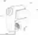
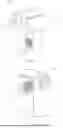
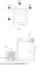


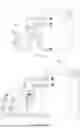
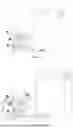
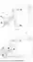
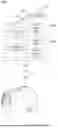
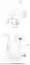
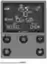
Sources:
- United States Patent and Trademark Office - verify current appl. status at the USPTO↗
Recent applications in this class:
- » 20250389431 2025-12-25
AIR CONDITIONER - » 20250271150 2025-08-28
AIR CONDITIONING SYSTEM - » 20250264230 2025-08-21
AIR CONDITIONER - » 20250085003 2025-03-13
Window Heat Pumps with Multiple Interior Air Outlets - » 20250035323 2025-01-30
FAN ASSEMBLY FOR AN AIR CONDITIONER APPLIANCE - » 20250003607 2025-01-02
NOISE REDUCTION APPARATUS AND AIR CLEANER INCLUDING THE SAME - » 20240401820 2024-12-05
AIR CONDITIONER - » 20240219037 2024-07-04
INDEPENDENT TEMPERATURE CONTROL FOR ROOMS - » 20230296267 2023-09-21
Independent temperature control for rooms - » 20230213222 2023-07-06
EVAPORATIVE COOLER
Recent applications for this Assignee:
- » 20250257901 2025-08-14
HEATERS WITH FLEXIBLE DUCTING ARRANGEMENTS