JOHNSON ELECTRIC HEAT PIPE
US20260043620A1
2026-02-12
19/292,018
2025-08-06
Smart Summary: A Johnson Electric Heat Pipe converts heat into electricity using a special system. It has a housing that contains a wick, a vapor exchange component, and a working fluid that changes between gas and liquid. When heat is applied, the working fluid evaporates, creating a low-pressure gas, while cooling down condenses the fluid and increases the gas pressure. This pressure difference is used to push the gas through an electrochemical cell, generating electrical energy. Additionally, the system recycles some of the heat from the condensation process to help with the evaporation, making it more efficient. 🚀 TL;DR
Abstract:
A Johnson Electric Heat Pipe direct heat to electricity converter includes a housing containing a wick, a vapor exchange recuperator, a two-phase working fluid, an ionizable non-condensable gas, preferably hydrogen or oxygen, and an electrochemical cell. The heat pipe is coupled to a heat source and a heat sink. The gas phase of the two-phase working fluid and the non-condensable gas exist at partial pressures within a constant pressure system. Heat from the source evaporates two-phase working fluid resulting in low partial pressure of non-condensable gas. Heat rejected to the heat sink condenses working fluid, resulting in high partial pressure non-condensable gas. The non-condensable gas partial pressure differential is applied across the electrochemical cell whereby non-condensable gas expands through the electrochemical cell and generates electrical energy. The vapor exchange recuperator recuperates a substantial portion of two-phase working fluid heat of condensation for use as two-phase working fluid heat of evaporation.
Inventors:
- Lonnie G. Johnson 88 🇺🇸 Atlanta, GA, United States
- David JOHNSON 1 🇺🇸 Smyrna, GA, United States
Applicant:
Interested in similar patents?
Get notified when new applications in this technology area are published.
Classification:
F28D21/0001 » CPC main
Heat-exchange apparatus not covered by any of the groups - Recuperative heat exchangers
F28D15/046 » CPC further
Heat-exchange apparatus with the intermediate heat-transfer medium in closed tubes passing into or through the conduit walls ; Heat-exchange apparatus employing intermediate heat-transfer medium or bodies in which the medium condenses and evaporates, e.g. heat pipes with tubes having a capillary structure characterised by the material or the construction of the capillary structure
F28D2021/0043 » CPC further
Heat-exchange apparatus not covered by any of the groups - ; Other heat exchangers for particular applications; Heat exchange systems not otherwise provided for for fuel cells
F28D21/00 IPC
Heat-exchange apparatus not covered by any of the groups -
F28D15/04 IPC
Heat-exchange apparatus with the intermediate heat-transfer medium in closed tubes passing into or through the conduit walls ; Heat-exchange apparatus employing intermediate heat-transfer medium or bodies in which the medium condenses and evaporates, e.g. heat pipes with tubes having a capillary structure
Description
CROSS-REFERENCE TO RELATED APPLICATIONS
This application claims the benefit of U.S. Provisional Patent Application No. 63/680,929, filed Aug. 8, 2024, entitled “Johnson Electric Heat Pipe,” currently pending, the entire contents of which are incorporated by reference herein.
BACKGROUND
Embodiments described herein relate to the conversion of heat energy to electrical energy or electrical energy to heat energy utilizing an engine having electrochemical cells.
The conversion of heat energy or chemical energy to electrical energy, or visa-versa, may be accomplished in a variety of ways. It is known that electrochemical cells such as batteries and fuel cells rely on chemical reactions wherein ions and electrons of a reactant being oxidized are transferred to the reactant being reduced via separate paths. The electrons are transferred electrically via wiring through an external load where they perform work. The ions are conducted through an electrolyte separator.
In fuel cells, the chemical reactants and reaction products are continuously supplied to and removed respectively from the electrochemical cell. In a similar manner as batteries, fuel cells operate by conducting an ionized species through a selective electrolyte which generally blocks passage of electrons and non-ionized species. The most common type of fuel cell is a hydrogen-oxygen fuel cell which passes hydrogen through one of the electrodes while oxygen is passed thorough the other electrode. The hydrogen ions are conducted through the electrolyte separator to the oxygen side of the cell under the chemical reaction potential of the hydrogen and oxygen. Porous electrodes on either side of the electrolyte are used to couple the electrons involved in the chemical reaction to an external load via an external circuit. The electrons and hydrogen ion reconstitute hydrogen and complete the reaction with oxygen on the oxygen side of the cell resulting in the production of water which is expelled from the system. A continuous electrical current is maintained by a continuous supply of hydrogen and oxygen to the cell.
To eliminate the need for a continuous supply of fuel and oxidizer and operate on heat instead, the present inventor originally disclosed a direct heat to electricity converter that uses an ionizable gas and a non-condensable gas to create a partial pressure differential of the ionizable gas across an electrochemical cell to produce electricity in U.S. Pat. No. 6,489,049 B1 awarded Dec. 3, 2002. Non-condensable gas accumulation as it passes from high partial pressure through the electrochemical cell to the non-condensable gas low partial pressure side eventually dissipates the pressure differential resulting in Carnot theoretical conversion efficiency. However, full theoretical dissipation occurs with infinitely large electrochemical cell area resulting in impractically low power density due to low average pressure ratio.
In an effort to overcome the forgoing limitations the Johnson Thermo-Electrochemical Engine disclosed in U.S. Pat. No. 7,160,639; filed Apr. 28, 2003 provided a first electrochemical cell operating at low temperature, a second electrochemical cell operating at high temperature, a conduit system including a heat exchanger that couples the two cells together, and a supply of ionizable gas such as hydrogen or oxygen as a working fluid contained within the conduit system.
The working fluid in the Johnson Thermo-Electrochemical Converter is compressed in the low temperature cell by supplying current at a voltage that is sufficient to overcome low temperature cell's Nernst potential, thereby driving hydrogen from the low pressure side of the membrane to the high pressure side. On the other hand, working fluid is expanded in the high temperature cell as current (power) is extracted under the high temperature cell's Nernst potential.
This voltage differential provides the basis for the JTEC engine. JTEC is a heat engine that uses hydrogen as a working fluid and two Membrane Electrode Assemblies (MEAs), one at low temperature and the other at high temperature. The low temperature MEA operates at a lower voltage than the high temperature MEA. The low temperature MEA compresses hydrogen at low voltage and the high temperature MEA expands hydrogen at high voltage. The net output power is determined by the difference in voltage between the two stacks.
Unlike conventional fuel cells where the open circuit voltage can be greater than 1V, the Nernst voltage from the hydrogen pressure differential across a membrane electrode assembly is in the range of only about 0.2 Volts with the difference between the high temperature MEA voltage and low temperature MEA voltage being in the range of 0.05V in low heat source temperature applications. Also, the resistive losses in efficiency associated with the impedance of two proton conductive MEA connected in series can cause a converter to have limited practical utility.
In an effort to improve performance, the present inventor further disclosed a JEHP configuration wherein a recuperative heat exchanger and a vapor barrier were included as additional structural components. The vapor barrier prevents premature condensation of the two-phase working fluid and the recuperative heat exchanger enhances heat to electric conversion efficiency. The recuperative heat exchanger thermally couples high partial pressure non-condensable gas flowing and liquid wicked from the low temperature side and transitioning to the high temperature side to the condensable and non-condensable gas mixture leaving the high temperature side and transitioning to the low temperature side. Although this configuration effectively improved recuperation of sensible heat as fluids flow between the high and the low temperature sections, heat of evaporation could not be effectively recovered. As a result, much of the energy supplied at the high temperature section to evaporate working fluid would be rejected at the low temperature section without being converted into electrical power yielding low conversion efficiency.
Still with a challenge achieving high efficiency levels using reasonable size electrochemical cells, the present inventor disclosed inclusion of a nozzle to increase flow velocity levels beyond flow promoted by gas partial pressure differentials alone. A pumping mechanism, a wick, produces sufficient liquid pressure to overcome the pressure drop across the nozzle. Working fluid evaporates at an increased pressure upstream of the nozzle and accelerates through the nozzle to promote convective heat transfer and improved gas mixing for higher power generation rates. The difference in total pressure across the nozzle provides the energy needed to achieve accelerated gas flow on the low partial pressure side of the electrochemical cell and thereby further increase the non-condensable gas pressure differential because of the Bernoulli effect. In this approach, heat input is converted into kinetic energy to produce reduced total pressure on the low partial pressure side of the MEA thus resulting in higher voltage and efficiency. The gas mixture pressure increases back to system pressure as it passes through a diffuser formed by the low-pressure MEA electrode(s) surface(s).
As the kinetic energy approach relies on high velocities, entropy increases associated with high turbulence and shock waves can significantly impact efficiency. Thus, a need exists for a practical way of providing a thermo-electrochemical heat engine that can approximate a Carnot equivalent cycle and that can operate over a wide range of heat source temperatures. It is the provision of such, therefore, that the present invention is primarily directed.
BRIEF SUMMARY
A Johnson Electric Heat Pipe (JEHP) direct heat to electricity converter is disclosed having a housing containing a first wick, a phase change heat recuperator, a two-phase working fluid, an ionizable non-condensable gas, preferably hydrogen or oxygen, and an electrochemical cell. The heat pipe is coupled to a heat source and a heat sink. The gas phase of the two-phase working fluid and the non-condensable gas exist at varying partial pressure relative to each other at a constant overall pressure within the housing. Heat from the source evaporates two phase working fluid to produce a portion of the mixed gas with low partial pressure of non-condensable gas, the resulting mixture being substantially condensable gas. On the other hand, heat rejected to the heat sink condenses working fluid to produce a portion of the mixed gas with high partial pressure of non-condensable gas, the resulting mixture being substantially ionizable non-condensing gas. The two portions of gas are applied to opposite sides of an electrochemical cell resulting in a non-condensable gas partial pressure differential across the electrochemical cell whereby non-condensable gas expands through the electrochemical cell and generates electrical energy. The phase change heat recuperator recuperates a substantial portion of two-phase working fluid heat of condensation for use as two-phase working fluid heat of evaporation.
BRIEF DESCRIPTION OF THE SEVERAL VIEWS OF THE DRAWINGS
The following detailed description of preferred embodiments will be better understood when read in conjunction with the appended drawings. For the purpose of illustration, there are shown in the drawings embodiments which are presently preferred. It should be understood, however, that the invention is not limited to the precise arrangements and instrumentalities shown.
In the drawings:
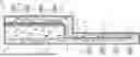
FIG. 1 is a schematic diagram of a Johnson Electric Heat Pipe (JEHP) in accordance with an example embodiment;
FIG. 2 is a schematic diagram of a structure of a wick from the JEHP of FIG. 1;
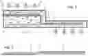
FIG. 3 is a schematic diagram of a JEHP with a low temperature MEA array added in accordance with another example embodiment;
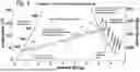
FIG. 4 is a plot showing a thermodynamic cycle representative of operation of the JEHP of FIG. 3; and
FIG. 5 is a schematic diagram of a JEHP with a venturi and wick in accordance with another example embodiment.
DETAILED DESCRIPTION
Certain terminology is used in the following description for convenience only and is not limiting. The words “right”, “left”, “lower”, and “upper” designate directions in the drawings to which reference is made. The words “inwardly” and “outwardly” refer to directions toward and away from, respectively, the geometric center of the device and designated parts thereof. The terminology includes the above-listed words, derivatives thereof, and words of similar import. Additionally, the words “a” and “an”, as used in the claims and in the corresponding portions of the specification, mean “at least one.”
It should also be understood that the terms “about,” “approximately,” “generally,” “substantially” and like terms, used herein when referring to a dimension or characteristic of a component, indicate that the described dimension/characteristic is not a strict boundary or parameter and does not exclude minor variations therefrom that are functionally similar. At a minimum, such references that include a numerical parameter would include variations that, using mathematical and industrial principles accepted in the art (e.g., rounding, measurement or other systematic errors, manufacturing tolerances, etc.), would not vary the least significant digit.
The MEA array may be heated to expand ionizable gas at relatively constant temperature for maximum power density and efficiency.
FIG. 1 illustrates an example embodiment and shows a housing 3 having high temperature section 2 and low temperature section 5. Ion conductive electrochemical cell membrane electrode assembly array (MEA) 6, wick 4, condensable gas vapor and ionizable non-condensing gas recirculation conduits 8 and 10, baffle 12 and condensation conduit 20 are contained within housing 3. Non-condensable, ionizable gas and hydrogen are used interchangeably herein when explaining operation of the invention. Similarly, gaseous working fluid, gas phase working fluid, condensable gas and steam are also used interchangeably herein when referring to the gas phase of the condensable working fluid in explaining operation of the invention. Finally, working fluid, liquid phase, liquid water and water are also used interchangeably herein when referring to the liquid phase of the condensable working fluid in explaining operation of the invention. Interchangeable descriptors in referring to materials that may be used in the invention are not to be construed as limitations on the invention.
Voltage is generated by applying an ionizable gas (hydrogen) partial pressure differential across Ion conductive electrochemical cell 6. Power is generated by current flow between the electrodes through an external load under the voltage differential as ionizable gas (e.g., hydrogen) is conducted through the MEA via oxidation-reduction electrochemical reactions. Connecting a load to terminals 7 and 9 results in current flow under the Nernst potential of MEA array 6. Current flow results in hydrogen flow through MEA array 6 into evaporation chamber 24.
MEA 6 is configured as an array of several membrane electrode assemblies electrically connected in series and may or may not share a common proton conductive separator. Wick 4 functions as a latent heat (phase change heat) recuperator. Recuperation of heat of evaporation/condensation enables very large condensable gas flow rates relative to ionizable gas flow rate. Section 14 of wick 4, baffle 12 and MEA 6 together form an evaporation chamber 24 with an exit 34 into condensation conduit 20. Housing 3 further contains liquid water, principally within wick 4, water vapor, and hydrogen gas, the amounts of each selected for effective operation of the converter. As illustrated in FIG. 1, heat 19 is supplied from a heat source to section 2 near MEA 6 and heat 15 is removed by a heat sink from low temperature section 5. The overall pressure within housing 3 is the same throughout. As such, decreasing the partial pressure or substantial content of one gas results in an increase in partial pressure or substantial content of the other. Conversely, an increase in partial pressure of one will cause a decrease in the partial pressure of the other.
Conduit 10 supplies mixed gas that is substantially ionizable gas in the form of high partial pressure hydrogen to anode side 13 of MEA 6. Cathode side 11 of MEA 6 is exposed to the inside of evaporation chamber where mixed gas that is substantially non-ionizable condensable gas in the form of a high partial pressure of water vapor is maintained by evaporation of water from wick 4. Wick 4 functions as a water vapor exchange membrane for recuperation of latent heat of evaporation.
It is understood that the vapor pressure of water within the wick is set by its temperature. Release of hydrogen into the evaporation chamber will cause water to evaporate from the wick to maintain its partial pressure consistent with the temperature of the water in the wick and thereby its mass ratio within the gas mixture. The resulting mixed gas exits evaporation chamber 24 through port 34 into conduit 20. Evaporation of water into chamber 24 from wick section 14 causes wick section 14 to cool as heat of evaporation of water is consumed. On the other hand, cooling of wick section 14 decreases the partial pressure of water therein, which results in water vapor within conduit 20 condensing into the wick giving up its heat of condensation. Water vapor within the gas mixture exiting chamber 24 through conduit 20 condenses on side 18 of wick section 14 releasing its heat of condensation as water on side 16 vaporizes, consuming heat of evaporation. Counterflow of gas mixture on opposite sides of wick section 14 results in recuperation of phase change heat from the water vapor exiting evaporation chamber 24 and removal of water vapor from the exiting gas mixture. With removal of water vapor from the gas mixture, the partial pressure of hydrogen gas increases. The partial pressure of hydrogen is further increased with heat removal and further condensation of water into wick 4 as the mixture passes through low temperature section 5. Wick 4 couples condensing water back to evaporation chamber 24.
At the end of low temperature section 5, the high hydrogen partial pressure gas enters high partial pressure supply conduit 10 at entrance 30. Conduit 10 supplies hydrogen at high partial pressure to MEA 6 as low partial pressure is maintained on the opposite side of MEA 6 by water evaporation into chamber 24. Electrical power is generated as heat is supplied to MEA 6 at elevated temperature and removed from low temperature section 5 causing continuous circulation of gases and liquid working fluid within housing 3.
Mixed gas with high hydrogen partial pressure leaving port 30 may be isolated from wick 4 by optional barrier 22 to prevent re-evaporation of water vapor into the gas flow from the wick. Recirculation conduit 8 provides a return path to port 30 to prevent accumulation of water vapor at the anode side of MEA 6 as hydrogen is removed from mixed gas at the anode and conducted into evaporation chamber 24.
Wick 4 functions as a pump that circulates water back to the evaporation chamber 24 as it condenses into wick 4 from conduit 20. FIG. 2 shows the structure of the wick, which may optionally include embedded barrier 23 to prevent potential diffusion of hydrogen therethrough directly from conduit 20. With an embedded barrier, the barrier conducts water to one end and around to the other side as indicated by arrows 25 as distribution of water is maintained uniform.
FIG. 3 shows low temperature section 5A with a modified configuration and the inclusion of second MEA array 40. A portion of the electrical power generated by MEA 6 is supplied to MEA 40. MEA 40 operates to remove hydrogen from conduit 20, compressing it from mixed gas in conduit 20 into conduit 10A via port 30A. MEA 40 compresses steam within conduit 20 by extracting hydrogen as it compresses hydrogen into conduit 17. The process occurs at constant temperature with heat removal.
FIG. 4 illustrates a thermodynamic cycle believed to be representative of the operation of the converter illustrated in FIG. 3. FIG. 4 shows the change in condensation pressure and temperature under the saturated liquid and saturated vapor quality dome. Lines 42 and 44 are representative of the change in steam partial pressure with temperature on opposing sides of section 14 of wick 4 in the constant total pressure system as mixed gases within chamber 24 and water within wick section 14 transition from low temperature near baffle 12 to high temperature near port 34. Final condensation process 40 ideally occurs at constant temperature within low temperature section 5. Constant temperature expansion 38 into the superheated region occurs within expansion chamber 12 near exit port 34. Isothermal expansion and compression with recuperative heat exchange in between represents the Ericsson thermodynamic cycle. The ideal Ericsson cycle is Carnot equivalent. An advantage of including steam recuperation enables higher power density than that achievable using a back-to-back MEA operating over a temperature differential with a recuperation heat exchanger but without steam as disclosed in U.S. Pat. No. 7,160,639 B2. In that invention, the output voltage is determined by the temperature and pressure differential under which it operates as defined by the Nernst equation.
The electrical potential due to an ionizable gas (i.e., the working fluid) pressure differential across a membrane electrode assembly is proportional to the natural logarithm of the ionizable gas (hydrogen in this example) pressure ratio, and can be calculated using Nernst Equation 1:
V OC = nR 2 F ⌈ ( T H - T L ) Ln ( P H HP H HP L ) ⌉
where VOC is open circuit voltage, R is the universal gas constant, T is the cell temperature, F is Faraday's constant, PH is the pressure on the high pressure side, PL is the pressure on the low pressure side, and PH/PL is the pressure ratio. E.g., Fuel Cell Handbook, J. H. Hirschenhofer et al., 4th Edition, p. 2-5 (1999). The voltage is linear with respect to temperature and is a logarithmic function of the pressure ratio. The net output voltage is determined by the difference in temperature between the high temperature MEA versus the low temperature MEA given that, ideally, the pressure ratio at both stacks is the same.
-
- SHPHT=Steam Pressure on the High-Pressure side of the High-Temperature MEA.
- SHPLT=Steam Pressure on the High-Pressure side of the Low-Temperature MEA.
- SLPHT=Steam Pressure on the Low-Pressure side of the High-Temperature MEA.
- SLPLT=Steam Pressure on the Low-Pressure side of the Low-Temperature MEA.
- HHPHT=Hydrogen Pressure on the High-Pressure side of the High-Temperature MEA.
- HHPLT=Hydrogen Pressure on the High-Pressure side of the Low-Temperature MEA.
- HLPHT=Hydrogen Pressure on the Low-Pressure side of the High-Temperature MEA.
- HLPLT=Hydrogen Pressure on the Low-Pressure side of the Low-Temperature MEA.
In a system where the total pressure is constant throughout and the pressure of hydrogen plus the pressure of steam equals the total system pressure:
V OC = nR 2 F ⌈ T H Ln ( HHP HT HLP HT ) - T L Ln ( HHP LT HLP LT ) ⌉
To simplify the equations, assume that there is primarily only hydrogen on the high-pressure side of both MEA such that the steam pressure within conduit 20 is intentionally very small and can be ignored. In this configuration the pressure of hydrogen on the High-Pressure sides of the High-Temperature and Low-Temperature MEA is equivalent to the Total Pressure of the System HHPH=HHPLT=TPS.
V OC = nR 2 F ⌈ T H Ln ( TP S HLP HT ) - T L Ln ( TP S HLP LT ) ⌉
On the Low-Pressures, the pressure of hydrogen is principally determined by the pressure of steam at a given location. On the Low-Pressure side of the High-Temperature MEA, the pressure of hydrogen equals the total system pressure minus the steam pressure at that location, (HLPHT=TPS−SLPHT). Similarly, on the Low-Pressure side of the Low-Temperature MEA, the pressure of hydrogen equals the total system pressure minus the steam pressure at that location, (HLPLT=TPS−SLPLT). Substituting gives:
V OC = nR 2 F ⌈ T H Ln ( TP S TP S - SLP HT ) - T L Ln ( TP S TP S - SLP LT ) ⌉
In examining the equations, note that as the vapor pressure of water increases with increasing temperature at the high-temperature MEA, the natural log (Ln) term approaches infinity. On the other hand, as the vapor pressure of water decreases with decreasing temperature at the low-temperature MEA, the Ln term approaches zero. Assuming equal hydrogen flow through the high and low temperature MEA, the higher difference in voltage indicates higher overall power output, the high-power output of the high temperature MEA minus the low power consumed in compressing hydrogen by the low temperature MEA.
FIG. 5 shows the JEHP configured to include a venturi 50 and a wick 52. Wick 52 is coupled to second heat input 54. Venturi 50 is coupled to expansion chamber 24. Heat from source 54 evaporates water from venturi wick section 52 to supply pressurized steam to venturi 50. Steam expanding through venturi 50 applies suction to evaporation chamber 24 and reduces the total pressure within chamber 24 below the mixed steam and hydrogen gas pressure in conduit 20. That produces a total pressure differential across both heat-water vapor mass exchange membrane section 14 as well as MEA 6. The net effect of the total pressure differential across MEA 6 is to amplify the non-condensable gas partial pressure differential resulting in increased Nernst voltage. The pressure differential across the phase change heat recuperator produces a condensable working fluid partial pressure differential sufficient to cause working fluid condensation on one side and evaporation on the other. The phase change heat is conducted across by the recuperator as the working fluid liquid wicks or otherwise migrates through.
The pressure differential enhances the kinetics of the converter in terms of heat and mass transfer rates as well as increases the output voltage of MEA 6. For example, assume a constant total pressure system where the partial pressure of hydrogen within chamber 24 is 10% of the total pressure, and the pressure of hydrogen at anodes 13 of MEA 6 is 90% of the total pressure. Under this condition, the Nernst voltage will be determined by the resulting hydrogen partial pressure ratio of 9. On the other hand, if the venturi 50 reduces the pressure within chamber 24 to 50% of the total system pressure and the partial pressure of hydrogen in chamber 24 is still 10%, then the pressure ratio of hydrogen across MEA 6 would be increased to 18.
As previously described, evaporation of water into chamber 24 from wick section 14 causes it to cool as heat of evaporation of water is consumed. Cooling wick section 14 decreases the vapor pressure of water therein below the partial pressure of water vapor within conduit 20, which causes water vapor within conduit 20 to condense onto the wick 14 and give up its heat of condensation. Under the pressure differential produced by venturi nozzle 50, water vapor condenses on side 18 of wick section 14 releasing its heat of condensation as water on side 16 vaporizes, consuming heat of evaporation. Counterflow of gas mixture on opposite sides of wick section 14 results in recuperation of phase change heat from the water vapor exiting evaporation chamber 24 and removal of water vapor from the exiting gas mixture. With removal of water vapor from the gas mixture, the partial pressure of hydrogen gas increases. The partial pressure of hydrogen is further increased with heat removal and further condensation of water into wick 4 and venturi wick section 52 as the mixture passes through low temperature section 58. Wick 4 supplies condensed water back to evaporation chamber 24 as venturi wick section 52 couples water back to heat source 54 and venturi 50 and as high partial pressure hydrogen passes through port 30 into conduit 10 and on to MEA 6 as previously described. Note that heat source 19 may be optionally omitted whereby heat supplied by source 54 is coupled to MEA 6. Heat is conducted from steam flow within conduit 20, across wick section 14 and on across chamber 24 to MEA 6.
While specific and distinct embodiments have been shown in the drawings, various individual elements or combinations of elements from the different embodiments may be combined with one another while in keeping with the spirit and scope of the invention. Thus, an individual feature described herein only with respect to one embodiment should not be construed as being incompatible with other embodiments described herein or otherwise encompassed by the invention.
It will be appreciated by those skilled in the art that changes could be made to the embodiments described above without departing from the broad inventive concept thereof. It is understood, therefore, that this invention is not limited to the particular embodiments disclosed, but it is intended to cover modifications within the spirit and scope of the present invention as defined herein.
Claims
We claim:1. A Johnson Electric Heat Pipe (JEHP) comprising:
a housing;
a two-phase working fluid;
an ionizable non-condensing gas;
a phase change heat recuperator; and
an electrochemical cell,
the JEHP being coupled to a heat source and a heat sink,
a gas phase of the two-phase working fluid and the non-condensable gas forming a mixed gas within the housing at varying partial pressures of the constituent gases with a substantially constant total pressure,
a first portion of the mixed gas being substantially ionizable gas and a second portion of the mixed gas being substantially two-phase working fluid gas being supplied to and forming an ionizable gas partial pressure differential across the electrochemical cell,
the electrochemical cell producing electrical power as ionizable gas expands through the electrochemical cell under the partial pressure differential as heat of expansion is supplied by the heat source,
the phase change heat recuperator maintaining a supply of substantially condensable gas to the electrochemical cell by capturing a portion of condensable gas from mixed gas leaving the electrochemical cell and supplying it back to the electrochemical cell via a condensation evaporation process to maintain the ionizable gas partial pressure differential,
heat rejected to the heat sink condensing two-phase gas from the mixed gas leaving the substantially non-condensable gas whereby the substantially non-condensable gas is supplied to the electrochemical cell opposite the substantially condensable gas to maintain the partial pressure differential of ionizable gas across the electrochemical cell.
2. The JEHP of claim 1, wherein the phase change heat recuperator is a wick containing liquid phase condensable working fluid.
3. A Johnson Electric Heat Pipe (JEHP) comprising:
a housing;
a two-phase working fluid;
an ionizable non-condensing gas;
a phase change heat recuperator;
a first electrochemical cell; and
a second electrochemical cell,
the JEHP being coupled to a heat source and a heat sink to convert potential energy differential between the heat source and heat sink into electricity,
the phase change heat recuperator, electrochemical cell, an expansion chamber, and a condensation chamber being contained within the housing,
a gas phase of the two-phase working fluid and the non-condensable gas being contained as a mixed gas within the housing at varying partial pressures relative to each other,
a first portion of the mixed gas being substantially ionizable gas and a second portion of the mixed gas being substantially two-phase working fluid gas being supplied to and forming an ionizable gas partial pressure differential across the electrochemical cell,
the first electrochemical cell producing electrical power as ionizable gas expands through the electrochemical cell under the partial pressure differential as heat of expansion is supplied by the heat source,
the phase change heat recuperator maintaining a supply of substantially condensable gas to the electrochemical cell by capturing condensable gas from a gas mixture leaving the first electrochemical cell and supplying condensable gas back to the first electrochemical cell via a condensation evaporation process to maintain the ionizable gas partial pressure differential,
electrical power being supplied to the second electrochemical cell to extract non-condensable gas from the gas mixture thereby increasing the partial pressures condensable gas on one side and non-condensable gas on the other, condensable gas condensing under the increased pressure, the resulting heats of compression and condensation being rejected to the heat sink, and the extracted non-condensable gas being supplied to the first electrochemical cell opposite the substantially condensable gas to maintain the partial pressure differential of ionizable gas across the first electrochemical cell.
4. The JEHP of claim 3, wherein the phase change heat recuperator is a wick.
5. A Johnson Electric Heat Pipe (JEHP) comprising:
a housing;
a two-phase working fluid;
an ionizable non-condensing gas;
a phase change heat recuperator;
a venturi wick section;
an electrochemical cell; and
a venturi,
the JEHP being coupled to a heat source and a heat sink,
a gas phase of the two-phase working fluid and the non-condensable gas forming a mixed gas within the housing at varying partial pressures of the constituent gases with a substantially constant total pressure,
a first portion of the mixed gas being substantially ionizable gas and a second portion being substantially two-phase working fluid gas being supplied to and forming an ionizable gas partial pressure differential across the electrochemical cell,
the electrochemical cell producing electrical power as ionizable gas expands through the electrochemical cell under the partial pressure differential as heat of expansion is supplied by the heat source,
the phase change heat recuperator maintaining a supply of substantially condensable gas to the electrochemical cell by capturing condensable gas from mixed gas leaving the electrochemical cell and supplying it back to the electrochemical cell via a condensation evaporation process to maintain the ionizable gas partial pressure differential,
the venturi wick section being coupled to the heat source, the heat sink and the venturi to supply water to the venturi as condensed from the mixed gas by heat removal to the heat sink, the venturi being coupled to the electrochemical cell, the heat source supplying heat to evaporate water from the venturi wick section with the resulting steam being driven through the venturi under pressure to produce a pressure differential,
heat rejected to the heat sink condensing two phase gas from the mixed gas, the resulting remaining gas being substantially non-condensable gas whereby the substantially non-condensable gas is supplied to the electrochemical cell opposite the substantially condensable gas to maintain the ionizable gas partial pressure differential of ionizable gas across the electrochemical cell.
6. The JEHP of claim 5, wherein the venturi produces a pressure differential across the electrochemical cell to amplify the non-condensable gas partial pressure differential.
7. The JEHP of claim 5, wherein the venturi produces a pressure differential across the phase change heat recuperator such that condensable working fluid partial pressure differential is sufficient to cause condensable working fluid condensation on one side of the phase change heat recuperator and evaporation on the other side as its liquid phase migrates through the phase change heat recuperator with heat conduction.
Images & Drawings included:


Sources:
- United States Patent and Trademark Office - verify current appl. status at the USPTO↗
Recent applications in this class:
- » 20260043619 2026-02-12
SYSTEM AND METHOD OF CONTROLLED CRYOGENIC COOLING AT LOW PRESSURE AND LOW SYSTEM VIBRATION - » 20250347475 2025-11-13
IMPROVED HEAT EXCHANGER DEVICE FOR AN AIRCRAFT TURBOMACHINE - » 20250085064 2025-03-13
THE SYSTEM AND THE METHOD FOR RECOVERY OF WASTE HEAT ENERGY CONTAINED IN OIL IN AN OIL-COOLED AIR COMPRESSOR - » 20250052517 2025-02-13
AIR-COOLED PRESSURIZING DEVICE WITH ENERGY RECOVERY FOR COMPRESSING OR PRESSURIZING A FLUID AND PROVIDED WITH AN IMPROVED COOLING - » 20240288225 2024-08-29
CERAMIC HEAT STORAGE BODY, METHOD FOR MANUFACTURING CERAMIC HEAT STORAGE BODY, AND COMPOSITION ESTIMATING METHOD OF CERAMIC HEAT STORAGE BODY - » 20240200884 2024-06-20
HEAT EXCHANGER - » 20220381521 2022-12-01
ADDITIVELY MANUFACTURED POROUS HEAT EXCHANGER - » 20200173735 2020-06-04
Natural gas liquid fractionation plant waste heat conversion to simultaneous cooling capacity and potable water using Kalina cycle and modified multi-effect distillation system - » 20200149827 2020-05-14
Natural gas liquid fractionation plant waste heat conversion to simultaneous power and cooling capacities using modified Goswami system - » 20190049193 2019-02-14
Natural gas liquid fractionation plant waste heat conversion to simultaneous power and cooling capacities using modified goswami system