FLETCHING PROTECTER
US20260043640A1
2026-02-12
18/797,518
2024-08-08
Smart Summary: The fletching protector is designed to keep the fletching on arrows safe. It has a part with a hole for the arrow shaft to go through. There is also a groove where the fletching can fit securely. This protector helps stop the fletching from getting bent or damaged. Overall, it makes arrows last longer and perform better. 🚀 TL;DR
Abstract:
According to an embodiment of the present invention, the fletching protector, wherein a body part provided with a through hole into which a shaft is inserted is comprised; wherein a receiving groove into which a fletching is inserted to be received is comprised; and wherein at least one fletching receiving portion provided with the receiving groove is comprised to prevent deformation and damage of the fletching, can be provided.
Inventors:
- JIN HEE SONG 2 🇰🇷 Busan, South Korea
- Yun Sub SONG 7 🇰🇷 Busan, South Korea
- Yun Il SONG 6 🇰🇷 Busan, South Korea
Assignee:
- SHINKWANG LEPORTS CO.,LTD 2 🇰🇷 Busan, South Korea
Applicant:
Interested in similar patents?
Get notified when new applications in this technology area are published.
Classification:
F42B6/06 » CPC main
Projectiles or missiles specially adapted for projection without use of explosive or combustible propellant charge, e.g. for blow guns, bows or crossbows, hand-held spring or air guns; Arrows; Crossbow bolts; Harpoons for hand-held spring or air guns; Archery arrows Tail ends, e.g. nocks, fletching
Description
BACKGROUND
The present invention relates to a fletching protector.
An arrow is a flying structure fitting on a bowstring and shot by a bow or a crossbow. The arrows consist largely of a shaft, a pile, and a fletching. The shaft is usually formed in a long and thin shape, with a pile at one end and a nock that the fletching and shaft are fitted on the bowstring on the other end.
In general, arrows that have left bowstrings of bows or crossbows fly toward their targets drawing parabolas, which swing back and forth and left and right based on the center of gravity of the arrows. In other words, the arrow does not fly straight toward the goal, but whirls and flies like the fish swimming. This phenomenon is called a paradox phenomenon, which plays a role in making the arrow's fletching fly straight by air resistance.
In addition, the arrow flies while rotating due to air resistance applied to the fletching of the arrow, and the rotating arrow flies much more stably than an arrow that does not rotate due to a gyro effect. In other words, a slight pitch is given to the direction of the fletching mounted on the shaft to rotate it so that the arrow moves stably.
That is, when an arrow in flight shakes from top to bottom or from side to side, the magnitude of the resistance generated by the gas molecules of the air is proportional to the pushing area of the gas molecules with respect to an object, so that the shaking of the fletching by the gas molecules in the air can be reduced by using the shape of the fletching.
However, the fletching is difficult to be attached to the outer circumferential surface of the shaft at an accurate angle, and there is a problem in that the fletching and the shaft are easily separated due to poor adhesion.
In addition, the fletching is generally formed of rubber material, and there is a problem in that the angle of the fletching in storage is bent or twisted due to rapid temperature change, humidity change, and ultraviolet rays during game or hunting, thereby reducing the accuracy.
In addition, in archery using a thin arrow, it is difficult to twist and attach a rubber fletching to the shaft, and the rotational force thereof is reduced, thus a plastic fletching is used a lot, but there is a problem in that the lifespan thereof is short.
As described above, it is necessary to protect the fletching generating various effects so that the fletching is not damaged or deformed due to the above problems while in storage or transferring.
DESCRIPTION OF THE RELATED ART
Document of Related Art
- (Patent Document 0001) Korean Patent Registration No. 10-0888383 (Mar. 12, 2009 announcement date)
SUMMARY OF THE INVENTION
The present invention has been made in an effort to provide a fletching protector, which can prevent arbitrary deformation of the fletching when storing arrows.
The purpose of the present invention is to provide a fletching protector capable of preventing damage to or breakage of a fletching.
The purpose of the present invention is to provide a fletching protector capable of transforming the shape of a fletching into a predetermined shape.
Objects of the present invention are not limited to the above-mentioned objects, and other objects not mentioned will be clearly understood by those skilled in the art from the following description.
According to an embodiment of the present invention, a fletching protector comprises a body part provided with a through-hole through which a shaft is insertable; and at least one fletching receiving portion including a receiving groove into which a fletching is inserted to be received to prevent deformation and damage of the fletching.
According to an embodiment of the present invention, the fletching receiving portion may be formed to have a predetermined inclination based on the longitudinal direction of the body part.
According to an embodiment of the present invention, the body part comprises the through-hole provided to communicate with the receiving groove, and the fletching may be provided to be insertable into the fletching receiving portion in a state in which the shaft is coupled to the through-hole.
According to an embodiment of the present invention, the body part may comprise at least one of polyethylene terephthalate (PET), silicon, polycarbonate, and ABS resin (Acrylonitrile Butadiene Styrene).
According to an embodiment of the present invention, the fletching receiving portion may form in a shape corresponding to the predetermined shape of the fletching.
According to an embodiment of the present invention, the body part may comprise an anti-slip member on a contact surface with the shaft.
According to an embodiment of the present invention, the fletching receiving portion may form to be curved in the longitudinal direction of the body part.
According to an embodiment of the present invention, the fletching may be received by inserting from a front end of the arrow.
According to an embodiment of the present invention, the fletching may be received by inserting from a rear end of the arrow.
According to an embodiment of the present invention, the fletching insertion portion and the fletching receiving portion may be provided on a surface facing the fletching.
According to an embodiment of the present invention, a fletching protector, which can prevent the fletching from being deformed when being stored, can be provided.
According to an embodiment of the present invention, a fletching protector may be provided to prevent the fletching from being damaged or broken.
According to an embodiment of the present invention, a fletching protector, which can modify the shape of the fletching into a predetermined shape, may be provided.
BRIEF DESCRIPTION OF DRAWINGS
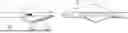
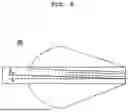
FIG. 1 is a perspective view of an arrow according to an embodiment of the present invention;
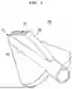
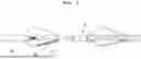
FIGS. 2 to 5 are perspective views of a fletching protector according to an embodiment of the present invention,
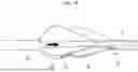
FIG. 6 is a perspective view illustrating an inclination of a fletching receiving portion provided at a body part according to an embodiment of the present invention.
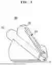
FIGS. 7 to 10 are drawings illustrating an insertion order of the fletching protector inserted from the rear end portion of an arrow according to an embodiment of the present invention.
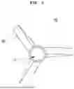
FIG. 11 is a drawing illustrating a fletching protector inserted from the front end portion of an arrow according to another embodiment of the present invention.
DETAILED DESCRIPTION OF THE INVENTION
Hereinafter, an embodiment of a fletching protector according to the present invention will be described in detail with reference to the accompanying drawings.
It should be noted that, in adding reference numerals to components of each drawing, the same components are denoted by the same reference numerals as possible even though they are illustrated in different drawings. In addition, in describing the embodiment of the present invention, when it is determined that a detailed description of a related known configuration or function interferes with the understanding of the embodiment of the present invention, the detailed description thereof will be omitted.
In describing the components of the embodiments of the present invention, terms such as first, second, A, B, (a), (b), and the like may be used. These terms are only for distinguishing the constituent elements from other constituent elements, and the essence, sequence, or order of the corresponding constituent elements are not limited by the terms.
Unless otherwise defined, all terms used herein, including technical or scientific terms, have the same meaning as commonly understood by those skilled in the art. It will be further understood that terms, such as those defined in commonly used dictionaries, should be interpreted as having a meaning that is consistent with their meaning in the context of the relevant art and will not be interpreted in an idealized or overly formal sense unless expressly so defined herein.
FIG. 1 is a perspective view of an arrow according to an embodiment of the present invention, FIGS. 2 to 5 are perspective views of a fletching protector according to an embodiment of the present disclosure, FIG. 6 is a perspective view illustrating an inclination of a fletching receiving portion provided in a body portion according to an embodiment of the present invention, FIGS. 7 to 10 are drawings illustrating an insertion order of the fletching protector inserted from a rear end portion of an arrow according to an embodiment of the present invention, and FIG. 11 is a drawing illustrating a fletching protector inserted from a front end portion of an arrow according to another embodiment of the present invention.
The fletching protector 100 may serve to prevent the fletching 12 of the arrow 10 from being arbitrarily damaged and/or deformed by receiving the fletching 12 in the fletching protector 100.
The arrow 10 shown in FIG. 1 includes a shaft 11, and the shaft 11 may be defined by being divided from a front end to which the pile 13 is coupled to a rear end to which the nock 14 is coupled. That is, the shaft 101 may be divided into a front end I and a rear end II along the longitudinal direction thereof from the front end to the rear end, and here, the fletching 12 may be provided at the rear end.
A fletching protector 100 according to FIGS. 2 to 11 may include a body part 110 where a through hole 111 through which a shaft 11 can be inserted is provided, a receiving groove 121 where a fletching 12 can be inserted and received, and at least one fletching receiving portion 120 where the fletching is received in the receiving groove 121 to prevent deformation and damage on the fletching 12.
The body part 110 may be provided in a cylindrical shape in which a through hole 111 is formed to be inserted into the shaft 11. The body part 110 may include a through-hole 111 into which the shaft 11 is inserted to be movable along a longitudinal direction of the shaft 11, and a fletching insertion portion 112 provided to communicate the through-hole 111 with the fletching receiving portion 120.
The fletching inserting portion 112 is provided to correspond to the fletching 12 provided at the shaft 11, and the fletching 12 may be inserted according to the movement of the body part 110 inserted into the shaft. More specifically, the fletching insertion portion 112 may be provided such that the through-hole 111 communicates with the receiving groove 121, so that the fletching 12 can be inserted into the fletching receiving portion 121 in a state in which the shaft 11 is coupled to the through-hole 111. The shaft 11 may be inserted into the through-hole 111 of the body part 110 to be moved in the longitudinal direction of the shaft 11, and the body part 110 may be moved along the shaft 11 so that the fletching 12 provided at the rear end portion II of the shaft 11 may be inserted into and received in the fletching insertion portion 112 and the fletching receiving portion 120 provided at one side of the body part 110.
An anti-slip member (not shown) may be provided on the body part 110. More specifically, an anti-slip member may be provided on an inner circumferential surface of the through hole 111 formed in the body part 110, and an anti-slip member is provided on an inner circumferential surface of the through hole 111 that is a contact surface with the shaft 111 to prevent the fletching protector 100 from being arbitrarily separated therefrom by contact between the anti-slip member and the shaft 11 after the shaft 11 is fitted into the anti-slip member. Preferably, the anti-slip member may be made of a rubber material but is not limited thereto.
The body part 110 may be provided with a fletching receiving portion 120 in which the fletching 12 is received, and the fletching receiving portion 120 may be provided with a receiving groove 121 where the fletching 12 is inserted and received in the fletching receiving portion 120. More specifically, the fletching receiving portion 120 may be provided with a receiving groove 121 into which the fletching 12 is inserted, and the receiving groove 121 may be formed to extend from the fletching inserting portion 112 so that the fletching 12 may be received in the fletching receiving portion 120 through the fletching inserting portion 112 and the receiving groove 121. As the fletching 12 is received in the fletching receiving portion 120 through the receiving groove 121, arbitrary deformation, damage, and the like may be prevented.
The fletching receiving portion 120 may be formed at the body part 10 corresponding to the number of fletching 12. A fletching receiving portion 120 may be formed in plural according to the numbers of fletching 12 at regular intervals at one end of the body part 110 thereby the fletching 12 may be inserted and received in the fletching receiving portion 120. More specifically, the fletching receiving portion 120 may be formed to correspond to a fletching 12 provided at the shaft 11. According to an embodiment, when the shaft 11 is provided with three fletching 12 at equal intervals in a fletching receiving portion 120, the body part 110 may be provided with three fletching receiving portions 120 at equal intervals of 120°, and when the fletching 12 are four, it is preferable that the body part 110 is provided with four fletching receiving portions 120 at equal intervals of 90°. The body part 110 provided with the fletching receiving portions 120 formed at equal intervals as described above may be inserted into the shaft 11 so that the fletching 12 can be received in the fletching receiving portions 120. As the fletching 12 is received in the fletching receiving portion 120, it is possible to prevent the fletching 12, which may be moved or stored, from being damaged, broken, and arbitrarily deformed.
FIG. 6 is a perspective view illustrating an inclination of a fletching receiving portion provided at a body part according to an embodiment of the present invention.
The fletching 12 may be attached to the shaft 11 in a direction parallel to a longitudinal direction of the fletching 12, or may be attached to the shaft 11 to have an inclination at a certain angle θ. As shown in FIG. 6, the fletching receiving portion 120 may be provided in the body part 110 to have a predetermined inclination corresponding to the angle θ at which the fletching 12 is attached to the shaft 11, and the fletching receiving portion 120 may be provided in the body part 110 to correspond to the angle θ at which the fletching 12 is attached at the predetermined angle θ so that the angle θ at which the fletching 12 attached to the shaft 11 is inclined may be maintained constantly.
In addition, the fletching receiving portion 120 may be formed to be curved in a longitudinal direction of the body part 110 according to the fletching 12. The fletching receiving portion 120 may be formed to be curved in a longitudinal direction of the body part 120 according to the fletching 12 and may receive the fletching 12 provided to be curved in the longitudinal direction of the shaft 11.
The fletching receiving portion 120 is individually inserted into the respective fletching 12 to support an angle of the fletching 12 and to prevent damage to and breakage of the fletching 12. In addition, according to the selection of those skilled in the art, the fletching 12 may be formed to be shaped in a predetermined shape.
Therefore, the fletching receiving portion 120 may be formed to correspond to a predetermined shape of the fletching 12, and a receiving groove 121 may be formed at one side thereof so that the fletching 12 provided in a predetermined shape may be fitted thereinto. The fletching 12 formed in a predetermined shape is fitted into the receiving groove 121 to fix an angle of the fletching 12 and protect the fletching 12 from an external environment.
The fletching 12 may be attached to the shaft 11 to be inclined at a certain angle θ in order to add a rotational force to the arrow. More specifically, the fletching 12 may be attached to the shaft 11 to be inclined at a predetermined angle θ to the longitudinal direction of the shaft 11, and the fletching receiving portion 120 may be provided at the body part 110 to be inclined at a predetermined angle θ corresponding to the fletching 12. Here, the predetermined angle may be an angle θ at which the fletching 12 is attached to the shaft 11. The fletching receiving portion 120 is provided at the body part 110 to be inclined at a predetermined angle θ to the axial direction and is received in the fletching protector 100 in a state in which the fletching 12 is inclined at the predetermined angle θ to the shaft 11, thereby being protected from an external environment.
The arrow 10 may have a different slope of the fletching 12 depending on the application. More specifically, the fletching 12 may be attached to the shaft 11 in a straight way in which the fletching 12 is attached in parallel to the shaft 11, in an offset way in which the fletching 12 is attached by forming a slope on the shaft 11, and in a helical way in which fletching 12 is attached as if the outer circumferential surface of the shaft 11 is wound, and, depending on the form where fletching 12 is attached on the shaft, rotation force of the arrow 10 may be increased and the paradox can be offset. Accordingly, the fletching receiving portion 120 may be formed in parallel to the body part 110 according to an attachment method of the fletching 12, may be formed to have a slope in the body part 110, and may be formed to wind the body part 110, but the present invention is not limited thereto, and the fletching receiving portion 120 may be formed in the body part 110 to correspond to a form in which the fletching 12 is attached to the shaft 11.
The fletching protector 100 may deform the fletching 12 into a predetermined shape. The fletching receiving portion 120 may be formed by being curved so that the fletching 12 is deformed to a predetermined shape according to a selection of a person of ordinary skill in the art, and the fletching 12 received in the fletching receiving portion 120 may be deformed to a predetermined shape. As the fletching 12 is deformed to a predetermined shape according to a selection of a person skilled in the art by the fletching receiving portion 120, the fletching 12 may further assist the rotation of the arrow 10.
The fletching protector 100 may be formed of a material comprising a strength equal to or greater than a predetermined strength to protect the fletching 12 from arbitrary deformation and damage and to deform the fletching 12 into a predetermined shape. More specifically, the fletching protector 100 may include at least one of polyethylene terephthalate (PET, polyethylene terephthalate), silicon, polycarbonate, and ABS resin (Acrylonitrile Butadiene Styrene) but is not limited thereto, and any material comprising a strength capable of receiving the fletching 12 to prevent the fletching 12 from arbitrary deformation and damage may be provided according to a selection of those skilled in the art.
Positions at which the fletching insertion portion 112 and the receiving groove 121 are formed may be determined according to the direction in which the fletching protector 100 is inserted into the arrow 10. The fletching-protector 100 may be inserted through a side surface of a front end portion or a side surface of a rear end portion of the arrow 10, and positions of the fletching insertion portion 112 and the receiving groove 121 where the fletching 12 is inserted may vary according to the direction in which the fletching-protector 100 is inserted into the arrow 10. A formation position of the fletching insertion portion 112 and the receiving groove 121 may be preferably provided at a side surface facing the fletching 12.
For example, when the fletching protector 100 is inserted through the rear end II of the arrow 10 that is the side surface at which the nock 14 of the arrow is provided, the fletching insertion portion 112 and the receiving groove 121 may be formed at positions facing the fletching 12 of the arrow 10, and when the fletching protector 100 is inserted through the front end I of the arrow 10 that is the side surface at which the pile 13 is formed, a direction in which the fletching insertion portion 112 and the receiving groove 121 are formed may be formed at position facing the fletching 12 of the arrow 10.
A fletching protector 100 according to one embodiment of the present invention comprises a body part 110 provided with a through-hole 111 into which a shaft 11 is inserted and at least one fletching receiving portion 120, one side of which has a receiving groove 121 for receiving fletching 12, to receive the fletching 12 and prevent arbitrary deformation of the fletching 12. The fletching protector 100 is inserted into the shaft 11 to receive the fletching 12, thereby preventing the fletching 12 from being damaged and arbitrarily deformed while in storage and transferring.
The embodiment of the present invention is not necessarily limited to the above-described embodiment, and it will be natural that various modifications and implementations in an equivalent range by those skilled in the art to which the present invention belongs are possible. Therefore, it will be said that the true scope of the present invention is determined by the claims to be described later.
DESCRIPTION OF CODE
-
- 10: Arrow
- 11: Shaft
- 12: Fletching
- 13: Pile
- 14: Nock
- 100: Fletching protector
- 110 Body part
- 111: Through hole
- 112: Fletching insertion portion
- 120: Fletching receiving portion
- 121: Receiving groove
Claims
1. A fletching protector comprising:
a body part provided with a through-hole through which a shaft is insertable; and
at least one fletching receiving portion comprising a receiving groove in which the fletching is inserted and received, so that the fletching is received in the receiving groove, thereby preventing deformation and damage of the fletching.
2. The fletching protector of claim 1,
wherein the fletching receiving portion forms to have a predetermined inclination based on a longitudinal direction of the body part.
3. The fletching protector of claim 1,
wherein the body part comprises the through-hole provided to communicate with the receiving groove, and wherein the fletching is provided to be insertable into the fletching receiving portion in a state in which the shaft is coupled to the through-hole.
4. The fletching protector of claim 1,
wherein the body part comprises at least one of polyethylene terephthalate (PET), silicon, polycarbonate, and ABS resin (Acrylonitrile Butadiene Styrene).
5. The fletching protector of claim 1,
wherein the fletching receiving portion forms in a shape corresponding to a predetermined shape of the fletching.
6. The fletching protector of claim 1,
wherein the body part comprises an anti-slip member on a contact surface with the shaft.
7. The fletching protector of claim 1,
wherein the fletching receiving portion forms to be curved in a longitudinal direction of the body part.
8. The fletching protector of claim 1,
wherein the fletching may be received by inserting from a front end of the arrow.
9. The fletching protector of claim 1,
wherein the fletching may be received by inserting from a rear end of the arrow.
10. The fletching protector of claim 3,
wherein the fletching insertion portion and the fletching receiving portion are provided on a surface facing the fletching.
Images & Drawings included:


Sources:
- United States Patent and Trademark Office - verify current appl. status at the USPTO↗
Similar patent applications:
- » 20100018884
Device for Protecting Arrow Fletchings
Recent applications in this class:
- » 20250264312 2025-08-21
HIGH IMPACT STRENGTH LIGHTED NOCK ASSEMBLY - » 20250264311 2025-08-21
HIGH IMPACT STRENGTH LIGHTED NOCK ASSEMBLY - » 20250130026 2025-04-24
Arrow Bending Axis Orientation - » 20240401920 2024-12-05
LIGHT-EMITTING NOCK FOR ARROWS - » 20240288252 2024-08-29
Light-emitting nock for arrows - » 20240118063 2024-04-11
LIGHTED ARROW - » 20240077290 2024-03-07
ILLUMINATED DEVICE FOR PRE-CHARGED PNEUMATIC GUN PROJECTILES - » 20240060755 2024-02-22
Tangentially Oriented Fletching - » 20230417521 2023-12-28
LIGHTED ARROW SHAFT - » 20230266105 2023-08-24
Lighted nock device
Recent applications for this Assignee:
- » 20240393091 2024-11-28
Arrow shaft