COMPARTMENT WITH WALL-MOUNTED STORAGE SYSTEM
US20260047697A1
2026-02-19
18/806,997
2024-08-16
Smart Summary: A wall-mounted storage compartment allows users to organize and customize their accessories easily. It consists of several panel sheets, which are made up of smaller segments. Each segment has parts that help it connect to the wall and hold accessories in place. There are slots between the panels where brackets can be attached for different accessories. These accessories can be moved around or removed as needed, making the storage system flexible and convenient. 🚀 TL;DR
Abstract:
A storage compartment that utilizes a wall-mounted system to adjustably arrange and customize various accessories. The storage system may have one or more panel sheets and each panel sheet may include one or more panel segments. Each panel segment may include a panel, a protrusion projecting from the panel, a support projecting from the panel, a first engagement member extending from the protrusion, and a second engagement member extending from the support. The engagement members are contactable with portions of a wall of the storage compartment. A slot may be formed between panels, the slot adapted to receive a bracket attached to each of the various accessories. Each accessory can be removable and adjustable within a slot.
Inventors:
- Ben Lavallee 3 🇺🇸 McDonald, PA, United States
- Jeremy O'Halloran 1 🇺🇸 Brentwood, PA, United States
- Edward E. Eckman 1 🇺🇸 Sewickley, PA, United States
- Richard Glogovsky 1 🇺🇸 Libertyville, IL, United States
- Jesus Carballido 1 🇺🇸 Chicago, IL, United States
Assignee:
- SA Consumer Products, Inc. 1 🇺🇸 Rolling Meadows, IL, United States
Applicant:
Interested in similar patents?
Get notified when new applications in this technology area are published.
Classification:
A47F5/0838 » CPC main
Show stands, hangers, or shelves characterised by their constructional features secured to the wall, ceiling, or the like; Wall-bracket display devices; Display panels, grids or rods used for suspending merchandise or cards supporting articles; Movable brackets therefor Rails or bars; Article supports therefor, e.g. brackets being slidably attached on the outside thereof
A47F5/08 IPC
Show stands, hangers, or shelves characterised by their constructional features secured to the wall, ceiling, or the like; Wall-bracket display devices
Description
FIELD OF THE INVENTION
The present invention relates to storage compartments, and in particular to a storage compartment that utilizes a wall-mounted system to support and store goods.
BACKGROUND
There are a number of types of storage compartments available for people to keep their belongings safe and secure. Safes, cabinets, closets, vaults and wardrobes are just a few examples of compartments that can be used to store belongings. Such compartments may utilize fixed shelving or cubbies to help organize belongings. One problem with most existing storage compartments is a lack of customization. Users may wish to reconfigure the shelving and cubbies to accommodate their belongings, however fixed shelving cannot be easily moved and cubbies are often not configurable. For example, a user may want to raise a shelf or cubby to make it easier and more comfortable to access the belongings stored there. This would be an onerous task for fixed shelving and cubbies.
Another situation where easily customizable storage would be useful is in a gun safe or cabinet. A user may desire to install supports at specific locations along the inner walls of the compartment to support the barrels of long guns or mounts for handguns. In conventional gun safes or cabinets, such customization would be difficult or impossible. Attaching supports to an interior wall of the compartment, or moving existing supports on a wall, would likely involve drilling and compromising the wall, thereby reducing its effectiveness in keeping contents safe and protected. Drilling the wall of a safe could ruin its fire resistance rating in addition to making the wall less secure. What is needed is a storage compartment, such as a safe, that has a system for easily positioning and rearranging supports and other accessories on an interior wall.
SUMMARY
Embodiments of the invention are defined by the claims below, not this summary. A high-level overview of various aspects of the invention is provided here to introduce a selection of concepts that are further described in the Detailed Description section below. This summary is not intended to be used in isolation to determine the scope of the claimed subject matter.
In brief, this disclosure describes, among other things, a storage compartment having a wall-mountable storage system and a method of constructing the wall-mountable storage system. The wall-mountable storage system includes a plurality of panels mounted to one or more inward walls of a storage compartment, and the storage compartment may be a safe.
Each panel segment further includes a slot which is formed therein, and slot may be defined by at least the retention surface and the overhang. Each slot is adapted to receive a bracket which is connected to one of many various accessories. Each accessory is thereby removable from and slidably engageable with each panel segment, and the accessories can accordingly be adjusted into customizable arrangements depending on the specifics of the storage application for which the wall-mountable storage system is used.
This disclosure also describes a method of constructing a storage compartment having the wall-mountable storage system described herein. The method includes adhering one or more reinforcement members to one or more inward walls of a storage compartment, which may be a safe. The method further includes securing one or more planks to one or more inward walls of the storage compartment, and bonding one or more of the linkable panel sheets to the one or more reinforcement members and one or more planks.
BRIEF DESCRIPTION OF THE DRAWINGS
Illustrative embodiments of the invention are described in detail below with reference to the attached drawing figures, and wherein:
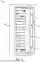
FIG. 1 is a front perspective view of a safe with its door open showing a wall mounted storage system.
FIG. 2 is a front perspective view of the wall-mounted storage system shown in the safe of FIG. 1.
FIG. 3 is a section view of the wall-mounted storage system mounted to a wall taken along line 3-3 of FIG. 2.
FIG. 4A is a fragmentary section view of the wall-mounted storage system mounted to a wall of FIG. 3.
FIG. 4B is an enlarged section view of the wall-mounted storage system mounted to a wall of FIG. 4A.
FIG. 5 is an exploded view of the wall-mounted storage system of FIG. 2 without accessories.
FIG. 6A shows an outer portion of the wall of the safe of FIG. 1.
FIG. 6B shows fireproofing added to the portion of the wall of FIG. 6A.
FIG. 6C shows adhesive applied to the back side of a wall-mounted storage system.
FIG. 6D shows the wall-mounted storage system of FIG. 6C being adhered to the wall of FIG. 6B.
FIG. 6E shows the wall-mounted storage system of FIG. 6C installed on the wall of FIG. 6B.
FIG. 7 is an enlarge front perspective view of a wall-mounted gun barrel rest engaged with the wall-mounted storage system shown in the safe of FIG. 1.
FIG. 8 is an enlarged front perspective view of the wall-mounted gun barrel rest of FIG. 7.
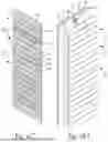
FIG. 9A is a top perspective view of a wall-mounted shelf.
FIG. 9B is a bottom perspective view of a wall-mounted shelf.
FIG. 10A is a top perspective view of a wall-mounted container.
FIG. 10B is a bottom perspective view of a wall-mounted container.
DETAILED DESCRIPTION
The subject matter of select embodiments of the invention is described with specificity herein to meet statutory requirements. But the description itself is not intended to necessarily limit the scope of the claims. Rather, the claimed subject matter might be embodied in other ways to include different components, steps, or combinations thereof similar to the ones described in this document, in conjunction with other present or future technologies. Terms should not be interpreted as implying any particular order among or between various steps herein disclosed unless and except when the order of individual steps is explicitly described.
Certain terminology will be used in the following description for convenience in reference only and will not be limiting. For example, the words “upwardly,” “downwardly,” “rightwardly,” “leftwardly,” “upper,” and “lower” will refer to directions in the drawings to which reference is made. The words “inwardly” and “outwardly” will refer to directions toward and away from, respectively, the geometric center of the embodiment being described and designated parts thereof. Said terminology will include the words specifically mentioned, derivatives thereof, and words of a similar import.
Referring to the figures, an exemplary embodiment of the invention comprises a storage compartment 10 having a storage system 12 mounted to an inner wall of the compartment. The wall mounted storage system 12 includes a series of slots 24 formed between panels 60, where several of the panels 60 may be formed on a single sheet 20. Various accessories 30 may engage with slots 24 and panels 60 such that the mounting locations of accessories 30 is easily changed and customized by the user.
In the embodiment shown in FIG. 1, storage compartment 10 may take the form of an enclosed cabinet or safe 34 that includes a door 36 and a door frame 38. It is to be understood, however, that the storage compartment 10 of the present invention may comprise many other storage receptacles, including closets and vaults, without departing from the scope of the embodiments described herein. Safe 34 may be any number of shapes and sizes depending on the specific storage applications for which safe 34 is to be used. For example, if safe 34 is used to store one or more rifles, then safe 34 may be relatively tall and narrow. Alternatively, if safe 34 is used to store smaller items, such as handguns or jewelry, then safe 34 may be relatively short and wide. The composition and construction of safe 34 may also vary depending on the specific storage applications for which safe 34 is to be used. For example, as is described in more detail below, safe 34 may include fireproofing materials to protect the contents stored therein from fire damage. But embodiments of safe 34 which are intended only to protect the contents therein from theft may not include such fireproofing materials.
A lock mechanism 40 may be embedded in door 36, and door 36 is pivotably attached to door frame 38. Door 36 is pivotable between at least an open position, wherein door 36 is apart from door frame 38 and the interior of safe 34 is accessible to users, and a closed position, wherein door 36 abuts door frame 38 and the interior of safe 34 is inaccessible to users. Lock mechanism 40 is selectively actuatable, with such actuation causing pins or bolts 44 to project out of or retract into lock mechanism 40. Lock mechanism 40 is typically actuated by rotating a wheel or helm 46 but may be actuated by other means without departing from the scope of the embodiments described herein. Security procedures may constrain actuation of lock mechanism 40. In some embodiments, for example, a user may need to enter an alphanumerical code or complete a biometric scan before actuating lock mechanism 40. When door 36 is in the closed position and lock mechanism 40 is actuated such that bolts 44 project out of door 36 and into door frame 38, door 36 is locked in the closed position.
Storage system 12 is mountable to a wall of safe 34. Typically, storage system 12 will be inside of safe 34 and mounted to an interior face of a wall. As will be described in more detail below, it is foreseen that in some embodiments of the invention, reinforcement members 50 and fire resistant planks 52 may be attached to one or more walls of safe 34 including the wall to which storage system 12 is mounted. For example, it should be understood that describing storage system 12 as mountable to a wall of safe 34 may refer to embodiments of the invention wherein storage system 12 is mounted directly to an interior face of the wall and/or wherein storage system 12 is mounted to the one or more reinforcement members 50 or more planks 52 attached to the wall.
As shown in FIGS. 1 and 2, in an exemplary embodiment, storage system 12 may be located inside of safe 34 and mounted to the back wall 58 of safe 34. It is foreseen that storage system 12 may be mounted to additional or different walls of safe 34 without departing from the scope of the embodiments described herein. It is also foreseen that storage system 12 may extend across and along the entirety of back wall 58 or a different wall of safe 34, and that storage system 12 may extend over only a portion of back wall 58 or said different wall of safe 34, with the remaining portions of such wall or walls being uncovered by the system. It is foreseen that wall mounted storage system 12 make take numerous configurations within safe 34 depending on the application. This could range from the system being on a small portion of a single wall to the system covering all walls.
Storage system 12 may comprise one or more panel sheets 20, where each sheet 20 includes one or more panels 60. The number of panel sheets 20 and the size of each panel sheet 20 depends on the specific storage applications for which safe 34 is to be used. Each panel sheet 20 may include a plurality of integrally formed panel segments 22 which extend longitudinally thereacross. In an embodiment, each panel sheet 20 includes four panel segments 22. It is to be understood, however, that each panel sheet 20 need not include a plurality of panel segments 22 and may instead include only a single panel segment 22. In embodiments of the invention wherein panel sheets 20 include a plurality of panel segments 22, it should be further understood that said plurality of panel segments 22 need not be integrally formed. An embodiment of the invention wherein each panel sheet 20 has a monolithic profile that includes a plurality of integrally formed panel segments 22 may exhibit certain advantageous traits such as relatively high load capacity, economical fabrication, and ease of assembly. But the plurality of panel segments 22 may be separable articles that are joinable to one another by fasteners, adhesives, or other means without departing from the scope of the embodiments described herein.
Referring to FIGS. 2-4B, each panel segment 22 includes a panel 60 having a first surface such as face 62 and a second surface such as back 64. Each panel 60 further includes a retention surface 66 and an overhang 68, which are described in more detail below. Face 62 includes a first edge such as upper edge 70 and a second edge such as lower edge 72. Face 62 is oriented toward the interior of safe 34 when storage system 12 is mounted to wall 58 of safe 34. Each panel 60 generally extends longitudinally across its respective panel sheet 20. The back 64 of panel 60 is oriented on the opposite side of panel 60 with respect to face 62, and back 64 is generally shorter than face 62. The back 64 of panel 60 includes a first or upper periphery 74 and a second or lower periphery 76. The back 64 of panel 60 is positioned to face wall 58 when storage system 12 is mounted thereto. In the exemplary embodiment shown herein, face 62 and back 64 of each panel 60 are approximately rectangular. It is to be understood, however, that the faces 62 and backs 64 may comprise other geometries without departing from the scope of the embodiments described herein. For example, faces 62 and backs 64 may be approximately square, approximately elliptical, or approximately triangular.
Each panel segment 22 may also include a protrusion 78 that extends rearwardly away from each panel 60 and toward wall 58 when storage system 12 is mounted to said wall. Protrusion 78 includes a ledge 80 that extends rearwardly from upper edge 70 and generally perpendicularly to face 62 of panel 60. A first engagement member 84 extends downwardly from a rearward portion of protrusion 78. Panel segment 22 may include a depression 86 proximate first engagement member 84, with a corresponding gap 88 formed between depression 86 and wall 58.
Each panel segment 22 further includes a support 90 that projects rearwardly and generally perpendicularly from each panel 60 toward wall 58 when storage system 12 is mounted thereto. Support 90 extends from panel 60 proximate lower periphery 76. A second engagement member 94 extends downwardly from a rearward portion of support 90. First engagement member 84 and second engagement member 94 contact respective portions of wall 58 when storage system 12 is mounted thereto. As described in more detail below, first engagement member 84 and second engagement member 94 are securable to respective portions of wall 58.
As best seen in FIGS. 2-4B, wall mounted storage system 12 includes a series of slots 24 formed between panels 60. For example, a slot 24 may be formed between the upper edge 70 of the face 62 of a first panel 60 and a lower edge 72 of the face 62 of a second panel 60 that is adjacent the first panel. Each slot 24 extends rearward from the faces 62 of the adjacent panels past the backs 64 of the panels. An additional cavity 82 may be formed that extends upwardly from slot 24 behind overhang 68. Cavity 82 is adjacent retention surface 66 and behind the bottom portion of panel 60. Cavity 82 may be sized to receive various hanging devices as discussed in more detail below.
As described above, storage system 12 may include a plurality panel sheets 20, and each panel sheet 20 may include a plurality of panel segments 22. As best shown in FIG. 3, in the exemplary embodiment of the invention described herein, each of a plurality of panel sheets 20 comprises a plurality of panel segments 22 which are adjacent one another in a stacked configuration, and the plurality of panel sheets 20 are linkable to one another. As shown in FIG. 4A, to facilitate engagement of adjacent panel sheets 20, each sheet 20 includes a tongue 102 and a channel 112. Tongue 102 may extend upwardly proximate the top portion 105 of a sheet 20 and channel 112 is typically located proximate the bottom portion 111 of the sheet. Channel 112 may be located on the back side of a panel 60 behind a bottom overhang 98.
When adjacent panel sheets 20 are engaged, tongue 102 may be received within channel 112. Tongue 102 may be integrally formed with support member 115, wherein the support member 115 is adjacent wall 58 and tongue 102 extends upwardly from support member 115 in a spaced configuration from wall 58. As shown in FIG. 4A, when tongue 102 is received within channel 112, two panel sheets 20 are linked or engaged such that a slot 110 is formed similar to slot 24 described above. An additional cavity 108 may be formed that extends upwardly from slot 110 behind bottom overhang 98. Slot 110 and cavity 108 are adapted to receive various hanging devices similar to slot 24 and cavity 82.
As described above, it is foreseen that some embodiments of the invention may include only a single panel sheet 20. It is also foreseen that one or more panel sheets 20 may include only a single panel segment 22. In such embodiments, the one or more panel sheets 20 may or may not include a tongue 102 and/or channel 112 depending on the specific storage applications for which safe 34 is to be used. For example, it is foreseeable that a storage system 12 may include only a single panel sheet 20 when originally mounted to a wall of safe 34, and that it may be desirable to reconfigure the storage configuration within safe 34 in the future by including an additional one or more panel sheets 20. In such embodiments, the single panel sheet 20 originally mounted to the wall of safe 34 may include a tongue 102 and/or channel 112 to preserve the option of including an additional one or more panel sheets 20 in the future. Alternatively, it is also foreseen that a storage system 12 may include only a single panel sheet 20 when originally mounted to a wall of safe 34, and that it may be desirable for the remaining portions of the wall or walls of safe 34 to have a conventional surface. In such embodiments, the single panel sheet 20 originally mounted to a wall of safe 34 may not include a tongue 102 and/or channel 112 as it may be undesirable to preserve the option of including an additional one or more panel sheets 20 in the future.
As best seen in FIGS. 7-10B, storage system 12 may include various accessories 30, such as a gun barrel rest 118, a shelf 120, and a bucket 122. It should be understood, however, that accessories 30 may include other devices, such as baskets, hangers, outlets, lights, and the like without departing from the scope of the embodiments described herein. Accessories 30 may be adjustably mounted to one or more panels 60 and may be manipulated into any number of customizable orientations and arrangements, such as the arrangement shown in FIG. 2.
Each accessory 30 may include a bracket 32 that is adapted and configured to engage with a panel segment 22 and fit within a slot 24. As best shown in FIGS. 7, 8, 9A, and 10A, each bracket 32 includes a support 114 and a retaining member 116. Support 114 may extend generally horizontally from a portion of accessory 30 and retaining member 116 may project upwardly from support 114. When an accessory 30 is mounted within a slot 24, bracket 32 may be oriented such that support 114 extends rearwardly from accessory 30 into slot 24 proximate the first ledge 80. Retaining member 116 may project upwardly from support 114 into cavity 82. Bracket 32 may be movable along slot 24 and the respective panel segment 22, thereby facilitating configuration of accessories 30 in customizable orientations and arrangements.
Referring now to FIGS. 7 and 8, barrel rest 118 includes a bracket 32, a spacer 124, a support member 126, and one or more saddles 128. Bracket 32 may extend from one side of spacer 124, and support member 126 may extend from the opposite side of spacer 124. In the exemplary embodiment shown herein, bracket 32, spacer 124, and support member 126 are oriented in approximately linear configuration. It should be understood, however, that the support member 126 need not be linearly oriented with bracket 32 or spacer 124. For example, support member 126 may be disposed in angular or approximately orthogonal relation relative to spacer 124, or a plurality of support members 126 may project from spacer 124 in a V-shaped or W-shaped orientation. It should further be understood that the support member 126 need not be linear and may instead be curved or angled.
As best shown in FIG. 8, one or more saddles 128 are formed in a side of each support member 126. Each saddle 128 is arched along its longitudinal axis and includes a seat 130 that is offset from and situated between two cantles 132. Because each saddle 128 is adapted and configured to support a gun barrel, a gun may be placed within safe 34 and tilted or leaned such that the barrel of the gun rests in the saddle 128. With a gun so oriented, cantles 132 prevent the gun barrel from sliding out of saddle 128. It is foreseen that saddles 128 may have varying sizes and depths to accommodate supporting barrels of different types of guns. For example, a comparatively large saddle 128 may be used to support the barrel of a shotgun, and a comparatively small saddle 128 may be used to support the barrel of a rifle.
Each saddle 128 may be attached to a mount 134 that is moveable between at least an extended position, wherein mount 134 protrudes outwardly from a support member 126 such that saddle 128 is spaced from a side of the support member 126, and a retracted position, wherein mount 134 is attached to support member 126 such that saddle 128 is not spaced from a side of the support member 126. Saddles 128 may also be fixed without the option of being extended or retracted. A saddle 128 can be attached to support member 126 with or without a mount 134. In the exemplary embodiment shown herein, a user may selectively move saddle 128 from the retracted position to the extended position. It is foreseen that mount 134 may be moved between the extended position and the retracted position by any number of mechanisms including pulling or pushing, rotation of a keyed shaft, or by operation of a pushbutton or an electromechanical actuator. By moving mount 134 between the extended position and retracted position, a user can desirably control the angle at which a gun stored within safe 34 tilts when supported by barrel rest 118.
Barrel rest 118 may include a prop 138 that projects from an edge of spacer 124 of barrel rest 118. In the exemplary embodiment shown herein, prop 138 projects outwardly and downwardly from spacer 124 in alignment with the side of support member 126 in which one or more saddles 128 are formed. However, it is foreseen that one or more props 138 may project in various directions from spacer 124, depending on the shapes and sizes of the gun barrels being supported by barrel rest 118. As best shown in FIG. 7, when barrel rest 118 is mounted to a panel sheet 20, at least one prop 138 abuts face 62 of a panel 60 thereby helping to support barrel rest 118 in a cantilevered position.
As shown in FIGS. 9A and 9B, shelf 120 includes a bracket 32, a platform 140, and a buttress 144. In the exemplary embodiment shown herein, platform 140 is approximately square and has a load surface 142. It should be understood, however, that platform 140 may comprise other geometries without departing from the scope of the embodiments described herein. For example, shelf 120 may be approximately rectangular, approximately trapezoidal, approximately triangular, or approximately elliptical. Platform 140 includes a load surface 142 that is substantially flat and is adapted and configured to hold various pieces of property that are storable within safe 34, such as ammunition, jewelry, money, and the like. It is foreseen that load surface 142 may include dividers for organizing the various pieces of property loaded thereon.
Platform 140 is supported by and centrally oriented atop buttress 144, such that load forces placed on platform 140 are channeled through a support plate 146 and one or more gussets 148 of buttress 144. Platform 140 abuts plate 146, and plate 146 has a plurality of holes 150 through which screws, bolts, or other mechanical fasteners (not shown) may extend to secure platform 140 to plate 146. In the exemplary embodiment shown in FIG. 9B, gussets 148 are disposed proximate opposite edges of plate 146 and project therefrom. But it is foreseen that one or more gussets 148 may be disposed at various locations along plate 146 depending on the geometry of platform 140 and the anticipated magnitude of the load placed thereon. A tab 152 may be attached to each of the gussets 148 in a generally perpendicular fashion. When shelf 120 is mounted to storage system 12, tabs 152 may abut face 62 of a panel 60 to help support shelf 120.
With reference now to FIGS. 10A and 10B, bucket 122 includes a bracket 32, a floor 154, walls 156, a lip 158, and one or more braces 160. Walls 156 may project in approximately orthogonal relation from edges of floor 154 to lip 158. In the exemplary embodiment shown herein, an approximately rectangular space is formed between floor 154 and walls 156 of bucket 122, and the edges and corners of bucket 122 may be generally rounded or chamfered. It is to be understood, however, that the space formed between floor 154 and walls 156 of bucket 122 may comprise other geometries without departing from the scope of the embodiments described herein. For example, the space formed between floor 154 and walls 156 of bucket 122 may be approximately cylindrical, approximately triangular, or approximately conic. Floor 154 of bucket 122 is substantially planar and is adapted and configured to hold various pieces of property that are storable within safe 34, such as ammunition, jewelry, money, and the like. It is foreseen that bucket 122 may include dividers for organizing the various pieces of property loaded therein.
One or more braces 160 may be disposed on a wall 156 and extend from lip 158 to floor 154. An edge 162 of each brace 160 is situated in approximately orthogonal relation with support 114 of bracket 32. In the exemplary embodiment shown in FIG. 10B, braces 160 are oriented beneath opposite ends of bracket 32, but it is to be understood that one or more braces 160 may be oriented at various locations relative to bracket 32 depending on the geometry of bucket 122 and the anticipated magnitude of the load placed therein. When bucket 122 is mounted to storage system 12, edge 162 of each brace 160 may abut face 62 of a panel 60 to help support bucket 122.
An exemplary method of constructing the storage compartment 10 and utilizing storage system 12 is now described in accordance with an embodiment of the invention. The method of constructing the storage compartment 10 is described with reference to construction of a safe 34, but it is to be understood that the method could be applied to another type of storage compartment 10, such as a closet or a vault, without departing from the scope of the embodiments described herein. Compartment 10 can take any number of forms including a cabinet, safe, vault, cupboard, or closet without departing from the invention. Also, the compartment 10 walls need not have any or all of the features described below, such as reinforcement members 50 and planks 52, to be able to utilize storage system 12. Any wall to which storage system 12 can be secured is capable of utilizing the system regardless of the structure of the wall.
As shown in FIGS. 6A-6B, the method of constructing the safe 34 may include a step of attaching one or more reinforcement members 50 to a back wall 58 of safe 34. It is foreseen that the method of constructing the safe 34 may further include attaching one or more reinforcement members 50 to additional or different walls of safe 34 without departing from the scope of the embodiments described herein. The one or more reinforcement members 50 may be welded or otherwise attached to back wall 58.
The reinforcement members 50 may take various forms including a series of furring or hat channels, where the reinforcement member 50 includes a web 164 and side walls 166 projecting from opposite edges of the web 164. Reinforcement member 50 may take any number of forms including having a transverse cross section that is U-shaped or C-shaped. Edges of side walls 166 abut portions of back wall 58 such that portions of side walls 166 and portions of back wall 58 comprise the legs along which a weld extends when each reinforcement member 50 is attached to back wall 58.
In the exemplary embodiment shown in FIG. 6A, reinforcement members 50 are adhered to back wall 58 at equidistant intervals across the width of the wall, with each reinforcement member 50 situated to run vertically from a lower edge 168 of back wall 58 to approximately an upper edge 170 of back wall 58. It should be understood, however, that the reinforcement members 50 may be adhered to back wall 58 at irregular intervals across the width thereof, with each reinforcement member 50 situated to run transversely across the width of back wall 58 without departing from the scope of the embodiments described herein.
The method may also include a step of securing one or more planks 52 to back wall 58 of safe 34. As best shown in FIG. 6B, the one or more planks 52 are typically situated adjacent to or between the one or more reinforcement members 50, with each plank 52 extending longitudinally from lower edge 168 of back wall 58 to approximately upper edge 170 of back wall 58. An adhesive (not shown) such as glue may be used to secure the one or more planks 52 to back wall 58.
In some embodiments of the method, the one or more planks 52 are formed of a fire-resistant material such as gypsum. Using fireproofing material to form each plank 52 functions to protect the contents of safe 34 from fire damage. In embodiments of the method wherein the safe 34 is intended to protect the contents stored therein from fire damage, the adhesive used to secure each plank 52 to back wall 58 may be a fire-rated glue. In other embodiments of the method, however, the one or more planks 52 may be formed of a material that lacks fire-resistant properties, and the adhesive used to secure each plank 52 to back wall 58 need not be a fire-rated glue. It is foreseen that using material that lacks fire-resistant properties to form each plank 52 may be appropriate in embodiments of the method wherein the safe 34 is intended only to protect the contents stored therein from theft.
The method may include a step of bonding at least one panel sheet 20 to the one or more reinforcement members 50 and the one or more planks 52. Referring to FIGS. 5, 6C, and 6D, each panel sheet 20 may bonded to one or more reinforcement members 50 and one or more planks 52 by applying adhesives such as one or more glue strips 174 to the rearward portions of one or more first engagement members 84 and second engagement members 94. With the adhesive so applied, each panel sheet 20 can be pressed against the one or more reinforcement members 50 and the one or more planks 52 which are secured to back wall 58. In some embodiments of the method, each glue strip 174 is oriented and configured to fit within the gap 88. In such embodiments, when each panel sheet 20 is forced against one or more reinforcement members 50 and one or more planks 52, each glue strip 174 contacts and extends along the depression 86 of a panel segment 22.
Additionally, the method may include a step of directly fastening each panel sheet 20 to the one or more reinforcement members 50 adhered to back wall 58 of safe 34. In the exemplary embodiment shown in FIG. 5, a plurality of fasteners 180 which may be self-tapping screws directly fasten each panel sheet 20 to one or more reinforcement members 50. Fasteners 180 may be aligned with a corresponding reinforcement member 50 and driven through a portion of each panel segment 22 of panel sheet 20 and into a corresponding reinforcement member 50. As shown in FIG. 6E, in some embodiments of the method each fastener 180 passes through a slot 24 formed in a panel segment 22 and into a corresponding reinforcement member 50 to secure the panel segment 22 t to the wall. In other embodiments of the method, each fastener 180 may be driven through a panel 60 and a support 90 of a panel segment 22 and into a corresponding reinforcement member 50. It is foreseen that fasteners 180 may be removable to facilitate selective reconfiguration of one or more panel sheets 20 depending on the specific storage applications for which safe 34 is to be used. Fasteners 180 may be used in addition to or in lieu of glue strips 174. The number of fasteners 180 used and the locations of the fasteners 180 will depend on the application and the desired strength of storage system 12.
Many different of the various components depicted, as well as components not shown, are possible without departing from the scope of the claims below. Embodiments of the technology have been described with the intent to be illustrative rather than restrictive. Alternative embodiments will become apparent to readers of this disclosure after and because of reading it. Alternative means of implementing the aforementioned can be completed without departing from the scope of the claims below. Identification of structures as being configured to perform a particular function in this disclosure is intended to demarcate those structures as including a plurality of possible arrangement of designs within the scope of this disclosure and readily identifiable by one of skill in the art to perform the particular function in a similar way without specifically listing all such arrangements or designs. Certain features and sub-combinations are of utility and may be employed without reference to other features and sub-combinations and are contemplated within the scope of the claims.
Claims
Having thus described the invention, what is claimed as new and desired to be secured by Letters Patent is as follows:1. A storage system attached to a wall of a storage compartment, said storage system comprising:
a first panel having a first protrusion;
a second panel having a second protrusion, said second panel proximate said first panel;
a first engagement member extending from said first protrusion, said first engagement member attached to the wall of the storage compartment;
a second engagement member extending from said second protrusion, said second engagement member attached to the wall of the storage compartment;
a slot between said first and second panels, wherein a cavity extends upwardly from said slot; and
an accessory having a bracket adapted to fit in said slot, wherein said bracket has a retaining member and a portion of said retaining member is adapted to fit within said cavity.
2. The storage system of claim 1, wherein said slot is generally horizontal.
3. The storage system of claim 2, wherein said cavity is located at least partially behind a portion of said first panel.
4. The storage system of claim 3, wherein said retaining member engages a retention surface adjacent said cavity.
5. The storage system of claim 4, wherein said accessory abuts at least a portion of said second panel when engaged with said retention surface.
6. The storage system of claim 5, wherein said accessory is a barrel rest.
7. A compartment with wall-mounted storage system comprising:
a compartment wall having a first side and a second side, said first side facing the interior of said compartment and said second side facing the exterior of said compartment;
a first panel having a first protrusion;
a second panel having a second protrusion, said second panel proximate said first panel;
a first engagement member extending from said first protrusion, said first engagement member secured to said first side of said compartment wall;
a second engagement member extending from said second protrusion, said second engagement member secured to said first side of said compartment wall;
a slot between said first and second panels, wherein a cavity extends upwardly from said slot; and
an accessory having a bracket adapted to fit in said slot, wherein said bracket has a retaining member and a portion of said retaining member is adapted to fit within said cavity.
8. The compartment with wall-mounted storage system of claim 7, wherein said slot is generally horizontal.
9. The compartment with wall-mounted storage system of claim 8, wherein said cavity is located at least partially behind a portion of said first panel.
10. The compartment with wall-mounted storage system of claim 9, wherein said retaining member engages a retention surface adjacent said cavity.
11. The compartment with wall-mounted storage system of claim 10, wherein said accessory abuts at least a portion of said second panel when engaged with said retention surface.
12. The compartment with wall-mounted storage system of claim 11, wherein said accessory is a barrel rest.
13. The compartment with wall-mounted storage system of claim 12, wherein said compartment wall is adapted to be fire resistant.
14. The compartment with wall-mounted storage system of claim 13, wherein said compartment wall includes gypsum board.
15. A compartment with wall-mounted storage system comprising:
a compartment wall having a first side and a second side, said first side facing the interior of said compartment and said second side facing the exterior of said compartment;
a first panel sheet having a plurality of panels, wherein at least one of said plurality of panels on said first panel sheet includes an engagement member secured to said first side of said compartment wall, wherein said first panel sheet includes a channel;
a second panel sheet having a plurality of panels, wherein at least one of said plurality of panels on said second panel sheet includes an engagement member secured to said first side of said compartment wall, wherein said second panel sheet includes a tongue and said tongue is received within said channel;
a slot formed between at least two of said plurality of panels on said first panel sheet; and
an accessory having a bracket adapted to fit in said slot.
16. The compartment with wall-mounted storage system of claim 15, wherein said slot is generally horizontal.
17. The compartment with wall-mounted storage system of claim 16, wherein said accessory is a barrel rest.
18. The compartment with wall-mounted storage system of claim 17, wherein said compartment wall is adapted to be fire resistant.
19. The compartment with wall-mounted storage system of claim 18, wherein said compartment wall includes gypsum board.
20. The compartment with wall-mounted storage system of claim 19, wherein said compartment wall includes a generally vertical reinforcement member proximate said gypsum board.
Images & Drawings included:


Sources:
- United States Patent and Trademark Office - verify current appl. status at the USPTO↗
Recent applications in this class:
- » 20250241462 2025-07-31
Systems for Hanging Articles Relative to Surface - » 20250057335 2025-02-20
PEG HOOK - » 20240065439 2024-02-29
Ulti-Wall Storage System - » 20230045766 2023-02-09
Systems for hanging articles - » 20200375374 2020-12-03
Wall rack with pivoting extensions - » 20200163471 2020-05-28
Configurable storage system - » 20200085212 2020-03-19
Display bar assembly and mounting bracket for merchandising displays - » 20180228303 2018-08-16
Bracket for product display grid and related methods - » 20170086602 2017-03-30
LADDERLESS MAGNETIC CEILING CLOTHES HANGER ADAPTER - » 20160198867 2016-07-14
Hanger Assembly for Displaying Products