EXERCISE DEVICE
US20260048293A1
2026-02-19
19/301,462
2025-08-15
Smart Summary: The exercise device has a triangular shape and is equipped with three wheels that let it move easily in any direction on different surfaces. It is designed to hold special inserts that can be used for various types of workouts. Users can perform different exercises by changing the inserts. The wheels make it convenient to use both indoors and outdoors. Overall, it offers a versatile way to exercise. 🚀 TL;DR
Abstract:
An exercise device includes a triangular base with at least three wheels mounted to a bottom thereof to allow for movement in all directions on various surfaces. The triangular base is configured to receive at least one insert suitable for use in performing a variety of exercises.
Inventors:
- Ralph Sasson 2 🇺🇸 Edison, NJ, United States
- Norman Cohen 1 🇺🇸 Edison, NJ, United States
- Ariel Schonfeld 1 🇺🇸 Edison, NJ, United States
Applicant:
Interested in similar patents?
Get notified when new applications in this technology area are published.
Classification:
A63B22/20 » CPC main
Exercising apparatus specially adapted for conditioning the cardio-vascular system, for training agility or co-ordination of movements using rollers, wheels, castors or the like, to be moved over the floor or other surface, during exercising
A63B21/00047 » CPC further
Exercising apparatus for developing or strengthening the muscles or joints of the body by working against a counterforce, with or without measuring devices Exercising devices not moving during use
A63B21/16 » CPC further
Exercising apparatus for developing or strengthening the muscles or joints of the body by working against a counterforce, with or without measuring devices Supports for anchoring force-resisters
A63B21/00 IPC
Exercising apparatus for developing or strengthening the muscles or joints of the body by working against a counterforce, with or without measuring devices
Description
CROSS-REFERENCE TO RELATED APPLICATIONS
The present application claims benefit of and priority to U.S. Provisional Patent Application Ser. No. 63/683,501 filed Aug. 15, 2024 entitled EXERCISE DEVICE, the entire content of which is hereby incorporated by reference herein.
BACKGROUND
Field of the Disclosure
The present invention relates to an exercise device including multiple wheels and multiple inserts elements.
Related Art
Plyometric exercise has become a popular fitness option for many people. Plyometric exercise involves repeated rapid stretching and contracting of muscles. In some cases, plyometric exercise may include the use of equipment, for example, sliding elements that may engage the feet or hands of a user to allow for rapid sliding on a floor or carpet to allow for rapid movement of the user's hand or foot. Such conventional elements, however, are typically suited only for operation on a particular surface or surfaces, which limit their usefulness. Further, such conventional elements are typically suited for engagement with a particular body part such that they are often only suitable for use with respect to certain exercises.
Accordingly, it would be beneficial to provide an exercise device that avoids these and other problems.
SUMMARY
It is an object of the present disclosure to provide an exercise device suitable for use on a variety of surfaces and including multiple inserts and bases to allow for contact with multiple body parts to perform a variety of exercises.
An exercise device in accordance with an embodiment of the present disclosure includes a body; at least three wheels mounted on a bottom of the body, wherein the at least three wheels are configured to allow the body to roll in any direction; a central cavity formed between the at least three wheels; a removable insert mounted in the central cavity, wherein the removable insert includes a flat surface configured for contact with a hand or foot of a user; and a friction pad movably mounted on a bottom surface of the central cavity from a retracted position where the friction pad is held above ground to an extended position where the friction pad is in contact with the ground and prevents the body from rolling.
In embodiments, the body is made of steel.
In embodiments, the body includes a silicone outer surface mounted on the body.
In embodiments, the silicone outer surface is molded separately and connected to the body.
In embodiments, each wheel of the at least three wheels is mounted in a caster configured to allow each wheel of the at least three wheels to rotate 360 degrees relative to a vertical axis.
In embodiments, each caster is removable from the body such that each wheel of the at least the wheels is removable from the body to prevent movement of the body.
In embodiments, each caster includes: a pair of spaced horns configured for positioning on opposite sides of the wheel; a lower retainer connected to the pair of spaced horns; a mounting plate fixedly connected to the body; a lower bearing provided between the lower retainer and an upper retainer; and an upper bearing provided between the upper retainer and the mounting plate such that the wheel is rotatable about the vertical axis.
In embodiments, the body includes a plurality of openings formed therein and configured as attachment points.
In embodiments, each opening includes a loop connected to the body.
In embodiments, the removable insert includes a semispherical portion extending from a first surface of the removable insert, opposite the flat surface.
In embodiments, the semispherical portion is received in the central cavity of the body when the removable insert is positioned over the central cavity in a first position.
In embodiments, the hemispherical portion extends upward when the removable insert is positioned over the central cavity in a second position.
In embodiments, the semispherical portion is made of soft silicone.
In embodiments, the semispherical portion includes a translucent outer skin, and an interior pattern configured to provide support.
In embodiments, the removable insert includes a rigid ring round a periphery thereof to provide additional strength.
In embodiments, the rigid ring includes at least one protrusion configured to be received in at least one slot formed in the silicone outer surface.
In embodiments, the device includes a removable handle configured for mounting on the body in place of the removable insert.
In embodiments, the removable handle includes: a base plate covering the central cavity; and an upward extending handle element extending from the base plate and positioned over the central cavity.
In embodiments, a bottom surface of the base plate includes high friction material to prevent sliding of the removable handle when not connected to the body.
An exercise device in accordance with an embodiment of the present disclosure includes a body; at least three wheels mounted a bottom of the body, wherein the at least three wheels are configured to allow the body to roll in any direction; a central cavity formed between the at least three wheels; a removable handle mounted over the central cavity; and a friction pad movably mounted on a bottom surface of the central cavity from a retracted position where the friction pad is held above ground to an extended position where the friction pad is in contact with the ground and prevents the body from rolling.
An exercise system in accordance with an embodiment of the present disclosure includes the exercise device discussed above. a second exercise device including: a second body; at least three second wheels mounted on a bottom of the body, wherein the at least three second wheels are configured to allow the body to roll in any direction; a second central cavity formed between the at least three second wheels; a second removable insert mounted in the second central cavity, wherein the second removable insert includes a second flat surface configured for contact with a second hand or second foot of a user; a second friction pad movably mounted on a bottom surface of the second central cavity from a retracted position where the second friction pad is held above ground to an extended position where the second friction pad is in contact with the ground and prevents the body from rolling; and a connecting bar connecting the exercise device described above to the second exercise device.
BRIEF DESCRIPTION OF THE DRAWINGS
The above and related objects, features and advantages of the present disclosure will be more fully understood by reference to the following, detailed description of the preferred, albeit illustrative, embodiments of the present invention when taken in conjunction with the accompanying figures, wherein:
FIG. 1 illustrates an exercise device including a base in accordance with an embodiment of the present disclosure;
FIG. 2 illustrates an exploded view of the base of the exercise device of FIG. 1 in accordance with an embodiment of the present disclosure;
FIG. 3 illustrates an exploded view of a castor of the exercise device of FIG. 1 in accordance with an embodiment of the present disclosure;
FIG. 4 illustrates the exercise device of FIG. 1 with a push up handle attached in accordance with an embodiment of the present disclosure;
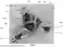
FIG. 5A illustrates the exercise device of FIG. 1 with an insert mounted in the cavity thereof in accordance with an embodiment of the present disclosure;
FIG. 5B illustrates a more detailed view of the insert illustrated in FIG. 5A in accordance with an embodiment of the present disclosure;
FIG. 6A illustrates the exercise device of FIG. 1 with the insert mounted in an inverted position in the cavity thereof in accordance with an embodiment of the present disclosure;
FIG. 6B illustrates the insert of FIG. 6A in more detail in accordance with an embodiment of the present disclosure;
FIG. 7 illustrates a more detailed view of the exercise device of FIG. 4 in accordance with an embodiment of the present disclosure;
FIG. 8 illustrates a more detailed view of a push-up handle separated from the exercise device of FIGS. 4 and 8 in accordance with an embodiment of the present disclosure;
FIG. 9A illustrates the exercise device of FIG. 1 with a friction pad in a retracted position in accordance with an embodiment of the present disclosure; and
FIG. 9B illustrates the exercise device of FIG. 1 with the friction pad in an extended position in accordance with an embodiment of the present disclosure.
DETAILED DESCRIPTION OF THE EXEMPLARY EMBODIMENTS
An exercise device 10 in accordance with an embodiment of the present disclosure is illustrated in FIG. 1, for example. In embodiments, the device 10 may include a body, or frame, 12 into which an insert 50 (see FIGS. 5A, 5B, 6A and 6B) may be removably mounted. In embodiments, the body 12 includes a central opening or cavity 12a configured to receive the insert 50. Three wheels 14a, 14b, 14b (see FIGS. 1 and 2, for example) may be mounted on a bottom of the body 12. In embodiments, the body 12 has a triangular configuration with the wheels 14a, 14b, 14c generally mounted at the three vertices thereof. In embodiments, the outer layer 12c of the body 12 may be made of a soft material for comfort, such as silicone. In embodiments, the body 12 may be made of steel, preferably pressed steel to provide strength and durability. In embodiments, the body 12 may include additional wheels and may have different shapes. In embodiments, the body 12 may be substantially square shaped with 4 wheels positioned at the vertices of the body 12, for example. In embodiments other shapes may be used. In embodiments additional or fewer wheels may be used. In embodiments, where other shapes are used, wheels may be positioned at the vertices of the different shapes. In embodiments, wheels may be positioned elsewhere on the body, that is, not necessarily limited to the vertices of the shape.
In embodiments, each of the wheels 14a, 14b, 14c may be mounted such that they are allowed to swivel relative axis Ax1 as indicated by arrow A1 in FIG. 1. In embodiments, the wheels 14a, 14b, 14c are mounted on the bottom of the body 12 via respective low profile brackets 22a, 22b, 22c that allow for smooth 360 degree rotation of the wheels relative to the body 12 such that the device 10 moves smoothly in any direction. In embodiments, the casters 22a, 22b, 22c also provide for low profile clearance as well. In embodiments, the wheels 14a, 14b, 14c may be made of hard rubber and may utilize a ball bearing construction to provide for smooth and quiet rolling over virtually any surface such that the exercise device 10 may be used on any surface and for virtually any exercise as it provides for easy movement in all directions. In embodiments, the wheels 14a, 14b, 14c are removably mounted to the body 12 so that they can be replaced if desired. In embodiments, each of the wheels 14a, 14b, 14c may be removably mounted on the body 12 such that the wheel and its associated brackets and casters may be removed as a unit.
In embodiments, a friction pad 13 may be provided on a bottom surface of the body 12. In embodiments, the friction pad 13 may be screwed into the bottom surface of the body 12 such that the height of the friction pad above the floor is adjustable. In embodiments, the friction pad 13 may be lowered to contact the floor to prevent the device 10 from moving, if desired, or to limit movement. FIG. 9A shows the friction pad 13 in a retracted position where it does not limit movement of the device 10. FIG. 9B shows the friction pad 13 in an extended position where it prevents or limits movement of the device. In embodiments, the friction pad 13 remains on the device and cannot be completely unscrewed and removed. In embodiments, the friction pad 13 may be secured to the body 12 and movable between two positions, the retracted position of FIG. 9A and the extended position of FIG. 9B. In embodiments, the friction pad 13 may be made of a pressed metal and may include a high friction pad or coating on the bottom to contact the floor.
As can be seen in the exploded view of FIG. 2, a soft silicone outer layer 12c may be molded over the body 12. In embodiments, the wheels 14a, 14b, 14c and casters 22a, 22b, 22c may be removably mounted at the vertices of the triangular body such that they can be replaced or repaired. In embodiments, a fixing element 15a, 15b, 15c may be provided to removably secure each of the wheels 14a, 14b, 14c to the body 12.
In embodiments, each of the wheels 14a, 14b, 14c may include a wheel element 102 mounted on a horizontal axle 104 (see FIG. 3) with a bearing 106 provided between the two to allow free rotation of the wheel element. The wheels 14a, 14b, 14c rotate about a horizontal axis, such as axis Ax2 in FIG. 1 in the direction indicated by arrow A2, for example. In embodiments, a bushing 108 may be provided to secure the axle 104 to the wheel element 102. In embodiments, a bearing sleeve 110 passes through the center of the wheel element 102. In embodiments, a washer 112 is provided on one side of the wheel element 102 and a nut 114 is provided on the opposite side to secure the axle 104 in place. The wheel element 102 rolls freely to allow the device 10 to move over virtually any surface. In embodiment, other configurations may be used to allow the wheel element 102 to rotated about the horizontal axis of the axle.
In embodiments, a pair of horns 120a, 120b may be provided on opposite sides of the wheel element 102 and may be part of the casters 22a, 22b, 22c, In embodiments, the horns 120a, 120b may be rotatably mounted relative to the body 12 such that the horns are rotatable about a vertical axis and the wheel element 102 rotates about a horizontal axis relative to the horns 120a, 120b. In embodiments, each caster 22a, 22b, 22c may include a lower retainer 124 to which the pair of horns 120a, 120b may be secured. A pin 122 may be used to connect the lower retainer 124 to a mounting plate 132 connected to the body 12 such that the retainer 124 and horns are rotatable relative to a vertical axis, such as axis Ax1, for example, which may extend through the plate 132. In embodiments, a lower bearing 126 is provided between the lower retainer 124 and an upper retainer 128 provided above the lower bearing. An upper bearing 130 is provided between the upper retainer 128 and the plate 132. In embodiments, the wheel element 102 rotates on the horizontal axle 104 about a horizontal axis to allow the device 10 to roll over substantially any surface. The horns 120a, 120b are rotatable about a vertical axis extending through the plate 132 such that the device 10 is movable in any direction on virtually any surface. In embodiments, the plate is mounted on a bottom surface of the body 12. In embodiments, the casters 22a, 22b, 22c may include different structures provided that they allow for rotation about a vertical axis.
In embodiments, the body 12 may include one or more openings 16a, 16b, 16c, which may be provided at the vertices of the triangular body 12. In embodiments, one or more openings may be provided elsewhere on the body 12. In embodiments, the openings 16a, 16b, 16c, may be integrated into the body 12 as illustrated in FIG. 1, for example. In embodiments, the one or more openings may be formed as loops added to the body 12. In embodiments, the openings 16a, 16b, 16c may be configured as attachment points for resistance bands or other exercise equipment for use by a user of the device 10. In embodiments, carbiners 140 (see FIG. 4, for example) may be attached to the openings 16a, 16b, 16c and may be attached to resistance bands or other devices. In embodiments, fewer or additional openings may be provided and may be provided in various positions on the body 12.
In embodiments, the central cavity 12a may be formed substantially in a center of the body 12. In embodiments, the central cavity 12a may be configured to receive a first insert 50 configured to receive a toe, foot or other body part of a user as can be seen in FIG. 5A, for example. In embodiments, insert 50 may have a semispherical portion 50a protruding from a surface thereof and configured to be received in the cavity 12a. In embodiments, the semispherical portion 50a may be made of a soft silicone. In embodiments, the semispherical portion 50a may be flexible to allow a user to easily grip it. In embodiments, an interior of the spherical portion 50a may have a visually appealing pattern or design which may be visible through a substantially translucent silicone outer skin as illustrated in FIG. 6B, for example. In embodiments, the interior may include a hexagonal pattern, as illustrated in FIG. 6B, however, any other pattern may be used. In embodiments, the hexagonal pattern may be made from plastic to support the user's weight.
In embodiments, the flat surface 50b of the insert 50 may be lined with silicone or a high friction material for comfort and to help retain the toe, foot or other body part of the user. In embodiments, a rigid ring 50c may surround the flat surface 50b of the insert 50 to provide additional strength and durability and allow the insert to be locked into place. In embodiments, the insert 50 may be mounted in the cavity 12a with the semispherical portion 50a facing up (see FIG. 6A) up to allow a user to grip the semispherical portion. In embodiments, the insert 50 may be mounted with the semispherical portion 50a facing down and being received in the cavity 12a.
In embodiments, the ring 50c may include protrusions 50c1, 50c2, 50c3 configured to be received in the slots 12e1, 12e2, 12e3 provided in the layer 12c of the body 12. In embodiments the protrusions 50c1, 50c2, 50c3 may rest on the metal body 12. In embodiments, the insert 50 may be mounted in the cavity 12a with the flat surface 50b facing up as in FIG. 5A or with the flat surface 50b facing down as in FIG. 6A.
In embodiments, as illustrated in FIG. 7, a handle 200 may be mounted on the body 12. In embodiments, the handle 200 may be mounted over the cavity 12a. In embodiments, a base plate 62 is positioned over the cavity 12a which is substantially flat. In embodiments, a handle element 60 may extend upward from the base plate and both may be removably mounted on the body 12. In embodiments, the handle element 60 may be made of a high strength and durable plastic. In embodiments, the outer surface of the handle element 60 may be textured to provide for better grip. In embodiments, the handle element 60 may be permanently secured to the plate 62. In embodiments, the handle element 60 may be manufactured separately from the plate 62 to simplify molding and manufacture, however, the handle element 60 should be securely fastened to the plate 62 to prevent separation during use. In embodiments, the handle element 60 and plate 62 may be used with the body 12 as illustrated in FIG. 7, for example. In embodiments, the handle element 60 may be used separate from the body 12, as illustrated in FIG. 8, for example. In embodiments, the bottom edge of the plate 62 may include silicone or another high friction material. In embodiments, the high friction material may be overmolded on the bottom surface of the plate 62 to prevent sliding. In embodiments, the silicone or other high friction material may be provided on a portion of the bottom of the plate 62. In embodiments, the silicone or high friction material will grip the ground such that the handle element 60 will not slip when in use. In embodiments, the handle element 60 may include one or more loops 64 to which a resistance band or carabiner may be attached, if desired.
While FIGS. 1-8 illustrate a single exercise device 10, in embodiments, users may use more than one exercise device 10 at a time. For example, while exercising, in embodiments, a user may use a separate exercise device 10 for each foot or leg and/or a separate exercise device for each hand or arm. In embodiments, a body bar may connect two exercise devices 10, for example, which may be used for upper body and/or abdominal stretching and contraction. In embodiments, the exercise device 10 may be part of an exercise system that may include at least a second exercise device 10.
Although the present invention has been described in relation to particular embodiments thereof, many other variations and modifications and other uses will become apparent to those skilled in the art. It is preferred, therefore, that the present invention be limited not by the specific disclosure herein.
Claims
What is claimed is:1. An exercise device comprising:
a body;
at least three wheels mounted on a bottom of the body,
wherein the at least three wheels are configured to allow the body to roll in any direction;
a central cavity formed between the at least three wheels;
a removable insert mounted in the central cavity,
wherein the removable insert includes a flat surface configured for contact with a hand or foot of a user; and
a friction pad movably mounted on a bottom surface of the central cavity from a retracted position where the friction pad is held above ground to an extended position where the friction pad is in contact with he ground and prevents the body from rolling.
2. The exercise device of claim 1 wherein the body is made of steel.
3. The exercise device of claim 1, wherein the body includes a silicone outer surface mounted on the body.
4. The exercise device of claim 3, wherein the silicone outer surface is molded separately and connected to the body.
5. The exercise device of claim 1, wherein each wheel of the at least three wheels is mounted in a caster configured to allow each wheel of the at least three wheels to rotate 360 degrees relative to a vertical axis.
6. The exercise device of claim 5 wherein each caster is removable from the body such that each wheel of the at least the wheels is removable from the body to prevent movement of the body.
7. The exercise device of claim 5, wherein each caster comprises:
a pair of spaced horns configured for positioning on opposite sides of the wheel;
a lower retainer connected to the pair of spaced horns;
a mounting plate fixedly connected to the body;
a lower bearing provided between the lower retainer and an upper retainer; and
an upper bearing provided between the upper retainer and the mounting plate such that the wheel is rotatable about the vertical axis.
8. The exercise device of claim 1, wherein the body includes a plurality of openings formed therein and configured as attachment points.
9. The exercise device of claim 8, wherein each opening includes a loop connected to the body.
10. The exercise device of claim 1, wherein the removable insert includes a semispherical portion extending from a first surface of the removable insert, opposite the flat surface.
11. The exercise device of claim 10, wherein the semispherical portion is received in the central cavity of the body when the removable insert is positioned over the central cavity in a first position.
12. The exercise device of claim 10, wherein the hemispherical portion extends upward when the removable insert is positioned over the central cavity in a second position.
13. The exercise device of claim 10, wherein the semispherical portion is made of soft silicone.
14. The exercise device of claim 10, the semispherical portion includes a translucent outer skin, and an interior pattern configured to provide support.
15. The exercise device of claim 3, wherein the removable insert includes a rigid ring round a periphery thereof to provide additional strength.
16. The exercise device of claim 15, wherein the rigid ring includes at least one protrusion configured to be received in at least one slot formed in the silicone outer surface.
17. The exercise device of claim 1, further comprising a removable handle configured for mounting on the body in place of the removable insert.
18. The exercise device of claim 1, wherein the removable handle includes:
a base plate covering the central cavity; and
an upward extending handle element extending from the base plate and positioned over the central cavity.
19. The exercise device of claim 1, wherein a bottom surface of the base plate includes high friction material to prevent sliding of the removable handle when not connected to the body.
20. An exercise device comprising:
a body;
at least three wheels mounted a bottom of the body,
wherein the at least three wheels are configured to allow the body to roll in any direction;
a central cavity formed between the at least three wheels;
a removable handle mounted over the central cavity; and
a friction pad movably mounted on a bottom surface of the central cavity from a retracted position where the friction pad is held above ground to an extended position where the friction pad is in contact with the ground and prevents the body from rolling.
21. An exercise system comprising:
the exercise device of claim 1;
a second exercise device comprising:
a second body;
at least three second wheels mounted on a bottom of the body,
wherein the at least three second wheels are configured to allow the body to roll in any direction;
a second central cavity formed between the at least three second wheels;
a second removable insert mounted in the second central cavity,
wherein the second removable insert includes a second flat surface configured for contact with a second hand or second foot of a user; and
a second friction pad movably mounted on a bottom surface of the second central cavity from a retracted position where the second friction pad is held above ground to an extended position where the second friction pad is in contact with the ground and prevents the body from rolling; and
a connecting bar connecting the exercise device to the second exercise device.
Images & Drawings included:


Sources:
- United States Patent and Trademark Office - verify current appl. status at the USPTO↗
Similar patent applications:
- » 20050003931
Exercise device, method of fabricating exercise device, and method and system for interaction with an exercise device - » 20170173324
EMS exercise device, EMS electrode, EMS garment, EMS stimulus generating unit, EMS signal cable, and EMS undergarment for an EMS exercise device, and method for operating the EMS exercise device - » 20190083847
CONTROL METHOD AND CONTROL DEVICE OF EXERCISE DEVICE, AND EXERCISE DEVICE - » 20230302343
Method for controlling user interface of exercise device and exercise device performing same - » 20070016444
Method for storing exercise performance of user of exercise device and exercise device - » 20140171269
DEVICE AND METHOD FOR LIMITING TRAVEL IN AN EXERCISE DEVICE, AND AN EXERCISE DEVICE INCLUDING SUCH A LIMITING DEVICE - » 20090029831
DEVICE AND METHOD FOR LIMITING TRAVEL IN AN EXERCISE DEVICE, AND AN EXERCISE DEVICE INCLUDING SUCH A LIMITING DEVICE - » 20110256988
Device and method for limiting travel in an exercise device, and an exercise device including such a limiting device - » 20130023383
Device and method for limiting travel in an exercise device, and an exercise device including such a limiting device - » 20060205569
Systems and methods for enabling two-way communication between one or more exercise devices and computer devices and for enabling users of the one or more exercise devices to competitively exercise
Recent applications in this class:
- » 20250010131 2025-01-09
EXERCISE APPARATUS - » 20240350861 2024-10-24
EXERCISE ROLLER SYSTEM - » 20240108943 2024-04-04
Cardio Fitness Machine - » 20230398404 2023-12-14
CONNECTED FITNESS TECHNOLOGY FOR SLIDE BOARDS - » 20230310929 2023-10-05
TWO-PERSON EXERCISE WHEEL MECHANISM - » 20230158366 2023-05-25
EXERCISE DEVICE - » 20220258001 2022-08-18
Multi-purpose exercise equipment - » 20220008782 2022-01-13
Exercise device - » 20220008781 2022-01-13
Exercise device - » 20210362001 2021-11-25
SELECTIVELY MOBILE EXERCISE APPARATUS, METHODS AND SYSTEMS