GOLF SWING TRAINER
US20260048314A1
2026-02-19
19/217,853
2025-05-23
Smart Summary: A golf swing trainer helps golfers keep their arms extended properly during their swing. It features a comfortable harness and an adjustable rod that connects to the golf club without damaging it. This rod can be locked in place and has a clamp that controls wrist angles. The system can also include sensors that track swing performance and send the data to a small computer for analysis. This way, users can improve their swings based on the feedback they receive. 🚀 TL;DR
Abstract:
A golf swing trainer system for maintaining a constant extension in the arms during the action of the swing for a constant swing circle radius. The golf swing trainer system includes an ergonomic harness, length-adjustable linear rod or a rod of several offset joints to avoid collision with the arms, a positive locking mechanism to set the length of the rod, and a tool-less hinged clamp at the end of the rod for non-destructively attaching to the top of a golf club and that controls the angle of the wrists during the swing. The swing trainer system may be deployed with a system of integrated sensors to collect data of swing performance and transmit these to a microcontroller for analysis and presentation to the user.
Applicant:
Interested in similar patents?
Get notified when new applications in this technology area are published.
Classification:
A63B69/3608 » CPC main
Training appliances or apparatus for special sports for golf Attachments on the body, e.g. for measuring, aligning, restraining
A63B2220/833 » CPC further
Measuring of physical parameters relating to sporting activity; Special sensors, transducers or devices therefor characterised by the position of the sensor Sensors arranged on the exercise apparatus or sports implement
A63B2225/093 » CPC further
Miscellaneous features of sport apparatus, devices or equipment; Adjustable dimensions Height
A63B2225/50 » CPC further
Miscellaneous features of sport apparatus, devices or equipment Wireless data transmission, e.g. by radio transmitters or telemetry
A63B69/36 IPC
Training appliances or apparatus for special sports for golf
Description
CROSS REFERENCE TO RELATED APPLICATIONS
The present application claims priority under 35 U.S.C. 119(e) to the provisional patent application filed on May 23, 2024 and assigned application No. 63/651,001 (Attorney Docket 16824-002). The contents of that application are incorporated herein.
FIELD OF THE INVENTION
The present invention relates to a golf swing training device that maintains the golfer's swing in a constant circular motion at a fixed radius.
BACKGROUND OF THE INVENTION
The prior art in the field of golf swing mechanical training aids includes various methods and devices aimed at improving swing efficiency, increasing clubhead speed, and optimizing ball trajectory. Golf swing research conducted by Robert ‘Bobby’ Jones (How I Play Golf, 1931), Ben Hogan (Five Lessons, The Modern Fundamentals of Golf, 1957), Joseph ‘Joe’ Norwood (Golf-o-Metrics, 1978), and Michael Hoke Austin (Golf Is Mental Imagery, 1985) show that the ideal golf swing maintains a continuous extension of the arms from the torso to the top of the golf club.
The angle of the wrist is also a very important aspect of the golf swing as this controls the clubface angle as it impacts the golf ball. According to this body of research, a golf club that maintains the clubface square to the swing arc retains golfer awareness of the location of the clubface and promotes better contact with the golf ball at impact.
Golfers struggle to follow these ideal techniques and many swing training aids have been developed attempting to train and ingrain in muscle memory these important golf swing concepts. Among the notable developments is the device invented by Michael Hoke Austin (commonly known as Mike Austin), which was known as ‘The Flammer’ (derived from the Latin word ‘flamma’ meaning ‘fire’ or ‘light’ used in this context to mean ‘enlighten’). The goal of this device was to control the arm extension length during the golf swing. Another goal of the device was to limit and control the axes about which the wrists were permitted to flex and extend.
The Flammer device accomplished these goals using a telescoping rod, a hinged clevis clamp on the end of the rod to which a club is attached and a ball-socket joint attached to a harness that was in turn attached to the top of the telescoping rod (see FIG. 19). But the golfer could not strike a golf ball while wearing the Flammer as the device materials and design were not engineered to withstand the impact forces present in a full-power golf swing. Instructional literature published by the inventor explicitly advised the user to not use the Flammer to hit golf balls. Additionally, the Flammer required tools to change out the club inserted into the clevis-hinging clamp at the actuator end (also known as the club end) of the telescoping rod. The Flammer's telescoping rod also did not include a positive locking mechanism to restrain the telescoping sections. Thus, repeated tightening of the extension sections was required to avoid the rod slipping into new extensions over time.
Other known training devices have attempted to maintain extension in the golfer's arms and alignment of the wrists to the plane of the swing during the golf stroke. Such devices utilize elastic bands wrapped around the torso and pulled taut by the user during the swing. Another device comprises a shirt-like article with narrow flexible sleeves through which the arms are inserted. The hands grasp the club and the sleeves attempt to keep the arms extended during the golf swing. However, these devices were of limited value in improving the golfer's swing.
Previous and current swing trainers are also deficient in several other aspects. Some trainers do not allow golfers to use their own clubs. Some trainers only control the swing radius through a segment of the swing arc, but not through the entire swing arc. Others do not permit adjustment of the circle radius according to the actual length of the golfer's arms or are adjustable only based on the club that is used with the trainer.
Regarding the electronic collection of swing data during the golf swing, several applications and sensor packages have been devised. These include wrist bands, visual imaging of human body motion during the swing, and ball tracker applications. However, these electronic sensor suites are deficient in that they are not integrated into a golf swing trainer package that forces the golfer to follow the ideal golfer motions during the golf swing. In other words, these sensors and imaging systems highlight golfer errors, but do not offer or teach techniques that reform the golfer's swing motions to follow accepted, if not ideal, swing motions. Frequent swing training using the golf swing trainer of the present invention will, in fact, not only reform, but drastically improve the golfer's swing mechanics.
SUMMARY OF THE INVENTION
Following is an ordered, but not exhaustive, list of the design and implementation deficiencies of the Flammer device that the present invention overcomes in a novel and non-obvious golf swing trainer.
-
- 1. Manufacturing quality suffered due to the crude design and inconsistent production of the device parts; parts were not interchangeable.
- 2. The device could not achieve full range of motion for a complete golf swing due to limitations in the degrees of freedom of the rotating joint.
- 3. The device was difficult for a human user to put on and take off.
- 4. The device was uncomfortable to wear.
- 5. The circular breast plate was not ergonomically shaped according to a human torso anatomy.
- 6. The device required tooling to attach the holding bracket or clevis to a golf club.
- 7. The wing nut on the telescoping mechanism was not securable as it lacked a positive locking mechanism, allowing the metal telescoping rod to loosen with repeated use.
- 8. The fundamental design and materials used in design meant the device could not be used to strike a golf ball as explicitly described by the published usage literature from the manufacturer.
- 9. The device was intended for use during only practice swings.
- 10. After prolonged use, the metal materials of the clevis clamp caused destructive damage to rubber golf club grips.
- 11. The ball-and-socket joint configuration limited the amount of rotational freedom necessary to traverse a full golf swing arc so that the ball can be struck with maximum force.
- 12. The device was difficult for women to use.
- 13. The device was difficult for individuals of diverse body types to use.
- 14. The device was difficult for individuals with disabilities or reduced limb functions to use due to the requirement to use tools to change clubs and the inability of the device to retain its length during the swing action due to the aforementioned lack of a positive locking mechanism.
The present invention is based on the highly-regarded theory that the preferred golf swing traces a circle. A circle, by definition, requires a constant radius. The center of this radius forms the point about which the circle is formed. The center is located where the golfer's cervical vertebrae meet the thoracic vertebrae of the human spine. This location is at the C7/T1 junction.
This rotational point of the swing occurs where the shoulders are turned in coordination with the flexion of the forward knee to separate the golf club from the ball, that is stages P1 to P4. See FIG. 14 that illustrates each of stages P1 through P10 of the golf swing. At the same time, during the swing the wrists are engaged into extension of the trailing hand and radial deviation of the forward hand. See FIG. 20 for illustrations of the kinesiological motions of a wrist. These motions control the clubface and thereby always maintain the clubface square to the path of the swing arc during the swing. See FIGS. 21A and 21B.
In particular, FIG. 21B illustrates the correct (orthogonal or 90 degrees) club face angle of club 210 relative to a golf ball 212. Lines 214 and 216 illustrate an open club face angle and a closed club face angle, respectively, causing the golf ball to slice or hook, respectively.
At the top of the backswing, at P4, the golfer's weight is transferred to the trailing leg. The downswing is initiated with a vertical movement of the right hand toward the right heel. This causes the weight to begin to shift cross-laterally to the forward leg, through stages P5 and P6. At P7, the right elbow unfolds to impact the ball with maximum power. The shoulders continue to turn through impact as the arms remain extended into stages P8, P9 and follow through to the finishing position at P10.
Maintaining a constant distance from the center of the swing circle at the C7/T1 vertebrae, to the clubface by maintaining a constant length from the top of the sternum of the to the top of the golf club gripped by the hands is critical to keeping the radius of the swing circle constant. That is, even as one arm folds and the other arm unfolds during the backswing, downswing, and follow-through, the overall length that forms the radius of the swing arc circle stays constant.
The arms and hands are the only contact between a golfer and the club. This golfer/club system can be modeled as a double-pendulum action. The upper pendulum is the invisible line between the swing circle center and the top of the club. The upper pendulum forms the inner circle of the total swing circle. The lower pendulum is the club itself which is held in both hands. Controlling the angle of the wrists as they travel along the inner circumference of the inner swing circle is of paramount importance to ensuring consistent contact of the clubface squarely behind the ball at the impact position, P7.
Since the length of the club is fixed and obviously cannot change during a golf swing, the only variable that can change the circumference of the inner swing circle (which is formed by the length of the arms to the top of the club) is the length of the arms. This variability in length can occur at any number of points in the golf swing, i.e., when the golfer folds and unfolds the right elbow in the backswing, separates the club from the ball, casts the arms outward in the downswing, or pulls the arms closer to the body in the follow-through. These types of errors are numerous and are known as ‘chicken-winging,’ ‘casting,’ ‘coming over the top,’ ‘shoulder-wobble,’ ‘left-arm collapse,’ ‘stuck right elbow,’ ‘over rotation,’ ‘church-bell ringing,’ ‘harpooning,’ ‘rope-tug pull,’ ‘cupped wrist,’ ‘bowed wrist.’ and so on.
The present invention discloses an apparatus for training a golfer in the correct positions of the arms, wrists, forearms, shoulders, torso, and hips during the golf swing by maintaining a constant or fixed radius from the center of the swing circle to the top of the club. Additionally, this invention mechanically controls the angle of the wrists throughout the swing circle by preventing the wrists from misaligning the clubface relative to the swing circle arc during the swing. This is achieved by the clevis clamp/hinge located at the end effector (the golf club end) of the rod which prevents the wrists from flipping or turning the club out of alignment with the swing plane.
Unlike previous golf trainers, the present invention allows the golfer to strike golf balls, to practice every shot in the game with the same trainer and various clubs, from long drives to mid-irons, to pitches, chips, and putts. By developing the golfer's muscle memory with repeated practice using the herein described swing trainer, a golfer develops a greater consistency in making correct golf shots when playing the game.
In view of the foregoing disadvantages inherent in the known types of golf swing trainers in the prior art, the present invention relates to a new, unique, and non-obvious swing trainer that teaches maintaining a constant radius in the golf swing with correct alignment of the wrist and hands relative to the club face.
The general purpose of the present invention, which will be described subsequently in greater detail, is to provide a new method and device that incorporates that method, for training golfers in the correct positions of the swing circle to enable them to hit golf balls, with their own clubs, with any club in their bag, adjustable to golfers of various sizes, ergonomically fitted, tool-less adjustment, durable, with the benefit of being grounded in solid golf theory, which is not anticipated, rendered obvious, nor even implied by any of the prior art golf swing training aids.
To attain these objectives, the present invention generally comprises an ergonomically designed harness with adjustable straps to accommodate various human torso sizes, a base plate affixed to the harness, a rotating central joint mounted on the base plate where the angle from the rotating joint to the base plate is fitted to be in line with the cervical vertebrae C7 at the center of the golf swing circle about which the shoulders rotate when the golfer stands at the angle of address at P1 (See FIG. 14.
The invention further comprises an adjustable telescoping rod comprising multiple segments, the length of which may be adjusted to fit the lie of the golf club, the club length, the length of the golfer's arms, and the golfer's selected angle of address. The telescoping rod utilizes a positive locking mechanism to prevent the rod length, and hence the radius of the swing circle, from changing during the golf swing. The rod may be attached directly from the base plate rotating joint and telescoped collinearly in line with the rotating joint.
In another embodiment, the rod comprises a serial arrangement of connecting, interlocking offset (that is, not linearly aligned) segments. The latter rod, advantageously, avoids any potential collisions and interferences between the rod and the user's arms, wrists, elbows, and hands during the action of the golf swing, while maintaining the desired fixed radius.
The invention further comprises a uniquely designed hinged clevis clamping mechanism that is non-destructively attached to the top region of a rubber golf club grip. This mechanism provides a secure connection to the club that prevents the club from rotating, or twisting, in the hands of the golfer during the swing. This ensures the clubface orientation stays fixed in line with the rod and only rotation of the rod with the hands in unison will turn the clubface as it traverses the swing path. This hinged clevis clamping mechanism also reduces interference with hand and wrist motions during the swing.
With the mechanical elements of the invention herein summarized, the swing trainer mechanism can further be deployed with an array of integrated electronic sensors linked by wired or wireless communications elements for collecting data that measures swing parameters and biometric information of the golfer during the swing. This data may be analyzed by algorithms including the deployment of innovative artificial intelligence or machine learning processes developed for golf swing data analysis. The information collected and analyzed includes, but is not restricted to, swing velocity, angle of attack (the vertical path the clubhead is traversing just as it strikes the ball), shoulder plane angle (the inclination of the shoulders relative to the ground from P1 through P10), impulse, etc.
There has thus been outlined, rather broadly, the more important features of the invention in order that the detailed description thereof may be better understood, and in order that the present contribution to the art may be better appreciated. There are additional features of the invention that will be described hereinafter and that will form the subject matter of the claims appended hereto.
In this respect, before explaining at least one embodiment of the invention in detail, it is to be understood that the invention is not limited in its application to the details of construction and to the arrangements of the components set forth in the prior or following description or illustrated in the drawings. The invention is capable of other embodiments and of being practiced and carried out in various ways. Also, it is to be understood that the phraseology and terminology employed herein are for the purpose of the description and should not be regarded as limiting.
BRIEF DESCRIPTION OF DRAWINGS
Various other objects, features and attendant advantages of the present invention will become fully appreciated as the same becomes better understood when considered in conjunction with the accompanying drawings, in which like reference characters designate the same or similar parts throughout the several views, and wherein:
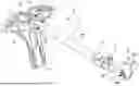
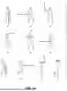
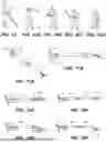
FIG. 1 shows an isometric right-side view of certain elements in one embodiment of the invention with a straight telescopic rod.
FIG. 2 shows an isometric left-side view of certain elements in one embodiment of the invention with a straight telescopic rod.
FIG. 3 shows a side view of the ergonomically designed base plate and angle offset of the rotating joint to which the rod is attached. Note that in a preferred embodiment, the rotating joint and base plate are not in a perpendicular relation, but offset by an angle to align the rod and the attached club with a center of rotation of the shoulders.
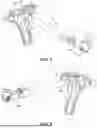
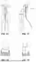
FIGS. 4A-4D show detailed views of various configurations of one embodiment of of a clamp for attaching an end of the rod to the top of a golf club grip.
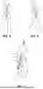
FIG. 5 shows a front view of the training device attached to a golfer shown in the address position of a golf swing.
FIG. 6 shows a front view of the training device attached to a golfer shown immediately after impact of the club with the ball, and proceeding into follow through position.
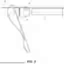
FIG. 7 shows an embodiment of the invention wherein the telescoping rod comprises a series of connecting offset hinged linkages, in lieu of the straight telescopic rod embodiment illustrated in FIGS. 5 and 6.
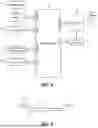
FIG. 8 shows a block diagram of a microcontroller for collecting and analyzing swing data.
FIG. 9 shows a side view of an offset linkage rod for one embodiment of the present invention.
FIG. 10 shows a facing view of the golf swing trainer on a golfer and locations of certain electronic sensors.
FIG. 11 shows an isometric view of the golf swing trainer on a golfer at the address position.
FIG. 12 shows an embodiment of a butterfly chucking clamp attached to a golf club grip.
FIG. 13 shows another embodiment of the butterfly chucking clamp having a longer attachment sleeve thereby providing a more secure attachment to a golf club grip.
FIG. 14 shows “P” positions of the golf swing.
FIG. 15 shows the golf swing circle in the swing circle as seen ‘down-the-line’ of the shot.
FIGS. 16A, 16B, 16C, and 16D show face-on views of the angle between a golfer's wrist and the club, as controlled by the golf swing trainer of the present invention to prevent the swing from extending outside the range of motion of a proper golf swing.
FIGS. 17A and 17B show an alternative embodiment to the ball-and-socket rotating joint of FIGS. 1 and 2, that is, a double universal joint mounted on a rotating base, with the rotating base attached to the base plate.
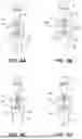
FIGS. 18A-18D show two embodiments of the rod and clamp: one clamp in-line with the telescopic rod (FIGS. 18A and 18C) and the other clamp offset by 90 degrees from the rod (FIGS. 18B and 18D). FIGS. 18A and 18B show the rod fully retracted. FIGS. 18C and 18D show the rod fully extended. The rod length can be extended and retracted to suit the user's desired swing radius profile.
FIG. 19 shows components of the Flammer prior art swing trainer.
FIG. 20 shows multiple kinesiological movement actions of the wrist, including a radial deviation and an ulnar deviation that are desired actions during a golf swing.
FIGS. 21A and 21B shows progressive steps of a golf swing in which the clubface is maintained square to the points on the swing circle so that the clubface arrives at the ball in the impact zone square to the intended line of flight of the ball.
FIG. 22 shows a block diagram of the electronic sensor components, microcontroller, power supply, mechanical assembly, and processing and display elements of the golf swing trainer of the present invention.
FIG. 23 shows mechanical components for attaching the swing trainer to a golf club.
FIG. 24 shows another view of the mechanical components of FIG. 23.
FIG. 25 shows the mechanical components and a golf club gripped by a golfer.
FIG. 26 shows certain elements of the swing trainer of the present invention as worn by a golfer.
DETAILED DESCRIPTION OF THE INVENTION
The golf swing is a complex action consisting of many dynamic motions of several parts of the human body. This includes a coordinated action of nerves, joints, muscles, ligaments, and bones to achieve the desired shot shape (straight ball, fade/left-to-right, draw/right-to-left, etc.), distance, and loft of the ball into the air.
The mechanical device of the present invention seeks to restrict multiple motions to force relevant parts of the human body to rotate and move in a controlled, but somewhat restricted fashion. Extension of the arms is controlled by affixing the arms to a fixed length training component at address and by limiting the range of motion that the wrists are permitted to traverse during the swing action. Maintaining a constant extension of the arms from ball address through backswing, impact, and follow through, ensures the user has a consistent and repeatable swing action as the club travels along the swing circle of the golf swing plane.
The mechanical trainer apparatus of the present invention further includes electronic sensors and data collection elements for collecting important swing data and analyzing the data. The results are immediately available for review by the golfer via visual display information presented on common electronic applications, such as on a mobile phone or personal computer.
Referring to FIG. 1, the ergonomically designed base plate 1, one component of the golf swing trainer 15, is intended for attachment to the upper diaphragm region of a human torso by means of straps (not shown) received within openings 5, 12, and 13. The harnessing apparatus is not limited to straps inserted through the depicted openings, as attachment to the torso can also be achieved using buckles, snap clips, or even seat belt buckles integrated into the base plate and mating buckle plugs affixed to the ends of straps, for a ensuring a secure fit of the base plate to the golfer's torso.
The base plate 1 is defines contours to permit a comfortable form-fit to the average human torso musculature. The contours are shown in the side view of FIG. 3. The base plate 1 is attached to a ball socket mechanism 4 with an offset angle shown clearly in FIG. 3. This offset angle aligns a telescoping rod 6 with the cervical vertebrae of the golfer (not shown in FIG. 3) as indicated by a line 39.
The base plate may be manufactured from a variety of materials, including metal, carbon fiber, plastic, wood, or other composite materials known to those skilled in the art.
The signal wires (not shown) from various sensors operative in conjunction with the swing trainer are routed to a processing device mounted within the base plate 1, such as at location 20. In another embodiment the signal wires are routed to another component of the swing trainer. In yet another embodiment, sensor data is wirelessly transmitted from the sensor to a separate device for processing.
The ball socket mechanism 4 comprises a ball 30 that rotates (pivots or swivels) within a socket 32, thus forming a swivel joint. The telescoping rod 6 is attached to the ball 30. Note that the socket 32 defines cutouts (also referred to as notches) 32A and 32B, allowing the rod 6 to be offset from a center of the socket 32 as the rod moves in to or within one of the cutouts 32A and 32B. The ball socket mechanism is rotatably affixed to the base plate 1. The mechanism 4 allows a full range of motion and rotational degrees of freedom as the telescoping rod moves during a golf swing. This feature is not disclosed by prior art. In particular, this feature is not disclosed by the Flammer swing trainer as the Flammer rod is connected to the Flammer breast plate such that motion of the rod relative to the breastplate is limited and does not enjoy the wide range of motion and rotation as exhibited by the present invention, due to the design and connection of the elements that comprise the mechanism 4 and its connection to the base plate 1
An upper rod segment 6A of the rod 6 is attached to a positive locking clamp mechanism 7, which allows the user to extend or retract the lower rod segment 6B. Once the desired length of the rod 6 is determined, a tab 11 is manipulated by the user to lock the rod into position.
The lower rod segment 6B is connected to a clevis hinge 9 (rigidly affixed in one embodiment) to which is rotatably affixed an attachment component 8 to which a golf club clamping mechanism is attached. The attachment component 8 rotates relative to the clevis hinge 9 about point/pin 9A. The clamping mechanism (not shown in FIG. 1) clamps to the top surface of a golf club grip (not shown in FIG. 1) and thereby affixes the telescoping rod 6 to the golf club. The attachment component 8 and the clamping mechanism may comprise any one of several different embodiments, which are described in later figures in further detail.
One embodiment of the golf swing trainer employs a butterfly chucking mechanism 40 for clamping the golf club grip. See FIGS. 4A-4D. As shown in each of the four figures, the rod 6 (specifically the lower rod segment 6B) is attached to the clevis hinge 9, which in turn is attached to the butterfly chucking mechanism 40.
FIG. 4A illustrates an initial configuration where a golf club grip 44 is inserted into open butterfly wings 42. In FIG. 4B (the locking configuration) the club is fully inserted and the butterfly wings are partially closed by operation/turning of a component 45. In FIG. 4C (the positive locking configuration) the wings 42 have been tightened by operation of a component 45, thereby closing the butterfly wings 42 over the golf club grip, creating a tight seal that does not damage the golf club grip. FIG. 4D illustrates the unlocking step during which the component 45 is operated to expand the butterfly wings 42 allowing removal of the golf club. The configuration of FIG. 4D is similar to the configuration of FIG. 4A and thus the golf club can be removed or inserted in the FIG. 4D configuration.
FIGS. 18A-18D show four possible configurations of the rod 6 (specifically the upper and lower rod segments 6A and 6B) and the butterfly chucking mechanism 40. In FIG. 18A the chucking mechanism 40 is in line with the upper rod segment rod 6A, which is the preferred embodiment. In FIG. 18B the chucking mechanism 40 is configured at 90 degrees relative to the upper rod segment 6A. FIG. 18C is similar to FIG. 18A with the rod extended in FIG. 18C. Similarly, FIG. 18D is similar to FIG. 18B, again, with the rod extended in FIG. 18D.
The golf club clamping mechanism for attaching the lower rod segment 6B to the golf club may comprise a variety of different mechanical components, including a wing nut V-clamps, or a circular strap clamp, such as a pipe lock or hose clamp. Additionally, the clamping mechanism may comprise a hinged vise clamp with a tightening screw or a butterflying chuck clamp, such as shown in FIGS. 4A-4D.
Yet another golf club clamping mechanism is illustrated in FIG. 23. One end of a threaded rod 230 is threadably engaged in a threaded hole 8A (See FIG. 1) in the attachment component 8. A second threaded end of the rod 230 is threadably received within a threaded hole 232A of a clamp 232. Rotation of a knob 234 moves vice jaws 235 and 237 together or apart and thereby captures the golf club grip 44 between the vice jaws.
FIG. 24 is another illustration of the clamp 232 attached to the attachment component 8.
FIG. 9 shows another apparatus for retaining the constant radius from the base plate to the golf club clamping mechanism via a series of offset linkages that are not colinear like the embodiments of FIGS. 1 and 2. A length of the offset linkages may be fixed or adjustable by means of locking hinges 7 such as disclosed in FIG. 1. FIG. 9 shows the ball 30 of the ball socket mechanism 4 and the first offset link 90. The telescoping section 92 is similar to the telescoping rod 6 of FIG. 1. A second offset link 94 returns the rod to the attachment component 8.
FIG. 7 illustrates an application of the embodiment of FIG. 9 for maintaining a constant radius and for keeping the telescoping rod from contacting the golfer's arms, forearms, wrists, or hands during the swing action, including at the impact position. The first offset link 90 is attached to the base plate via the ball socket mechanism 4 (not shown). The telescoping section 92 returns the telescoping rod into alignment with the golf club, thereby preserving the design intent of holding a constant radius from the golfer's chest to the top of the golf club.
FIG. 5 shows the golf swing trainer of the present invention as worn by the golfer at the address position of a golf swing (known as P1, see FIG. 14).
FIG. 6 shows the configuration of the golf swing trainer of the present invention immediately after impact with the golf ball, that is, in the transition from P7 to P8.
FIGS. 5 and 6 illustrate maintenance of the constant radius with the clevis hinge 9 preventing the club from turning bowing or cocking (by motion of the wrists) in directions that would cause the clubface to open (creating a shot to the right, known as a ‘slice’) or for the clubface to close (creating a shot to the left, known as a ‘hook’).
The swing trainer further comprises an array of sensors, a data processor, and related elements. In one embodiment, FIG. 8 depicts a system block diagram of a microcontroller 80, sensors 81 for collecting data related to the golfers swing while using the trainer of the present invention. The microcontroller 80 is powered as is known by those skilled in the art. In one embodiment a voltage of about 3.3 VDC is sufficient.
Signals are input to or output from the microcontroller 80 through various general purpose input/output pins (GPIO) and UART pins (universal asynchronous receiver transmitter).
The microcontroller receives data from various sensors 81, e.g., accelerometers and gyro sensors for processing to provide the golfer with information (in both numerical and graphical form) related to measured golf swing parameters, such as swing speed, force transferred to the golf ball, and clubface orientation.
The output data from the microcontroller can also be sent to a Bluetooth low energy (BLE) module 82 and transmitted, via an antenna 84, to the golfer's receiving device for additional analysis and presentation to the user on an application such as a mobile phone program or personal computer program (not shown).
The LED indicator 85 provides battery charging status information as well as indicating the operating mode activated by operation of a power switch 86. A Bluetooth switch/button 87 and the BLE module 82 enables pairing with a user's Bluetooth enabled device so that accelerometer data (such as angular velocity and G-force data as collected by the sensors) can be transmitted via the antenna 84 utilizing Bluetooth communication protocols.
See FIGS. 10 and 11 for the location of certain sensors referred to above.
The measured parameters can be algorithmically analyzed by software resident on the receiving device (not shown) or integrated in the base plate 1, and displayed to provide feedback to the golfer.
The block diagram further depicts a battery 87 and a charging section 88 for supplying power to the microcontroller and sensors mounted at various locations on the swing trainer.
FIG. 22 depicts a block diagram of another embodiment of a microcontroller 220 and associated components for use with the golf swing trainer of the present invention. FIG. 22 illustrates the relationship between component parts of the electronic sensing system, the mechanical swing trainer apparatus, the data analysis program, and the visual output display.
Power is supplied to the microcontroller 220 and sensors 221 from a power supply 222. The microcontroller 220 and the sensors 221 are favorably mounted on the swing trainer as indicated.
The measured parameters (data) collected by the sensors is input to the microcontroller via a signal line 223. Output data from the microcontroller 220 is input to a wireless transmitter 224 and transmitted to a receiver 225. Within the receiver 225, the data is analyzed by an analysis program 226 and the results displayed to a golfer 227 on a display 228.
One example of data collected and analyzed relates to clubhead speed. This clubhead speed can be collected from an accelerometer sensor mounted at the end of the telescoping rod 6. This accelerometer sensor transduces the gyroscopic input from the swing into electrical signals that are input the microcontroller 220 (or 80) via GPIO pins. The microcontroller converts the electrical signals into data packets that are transmitted to the receiver 225 and then processed by the analysis program algorithm 226. Finally, clubhead speed data is displayed on the visual display output 228.
The analysis algorithm utilized by the processor may be configured for specific types of data and to generate a desired output. This algorithmic analysis of the data includes mathematical processing of raw physical data and predictive analytics based on the inputs that derive expected performance outputs. Inputs fed to the algorithm may include, but should not be construed to be limited to, the type of club being used by the golfer in the mechanical swing trainer, loft of the club, age of the golfer, height and weight of the golfer, and other pertinent information related to the golfer's innate characteristics. This information is then processed with the swing data collected from the sensors, as desired by the specific embodiment of the sensor integration, to create a presentation of this information on the visual output display 225 to the golfer.
Additional golf swing parameters that can be collected from sensors include: length of the swing arc, clubhead speed, angle of attack, smash factor, clubface orientation, and number of swing repetitions by the user during a practice session or series of practice sessions.
Sensors may be placed at several different locations on the swing trainer, including the base plate, anywhere along the telescoping rod, the rotating joints extending from the base plate, the golf club attachment joint, the torso straps, the hinged clevis/clamp extending from the lower rod segment, the clamp mechanism that is in contact with and attached to the golf club.
The embodiments of the mechanical swing trainer and methodology employed for swing data collection and analysis include a diversity of information that is desirable for golfers to know to maximize the performance of their swings. Types of sensors that may be mounted and data collected and analyzed include, but should not be construed to be limited to, gyroscopic, accelerometer, pressure, biometric, thermal, moisture, infrared, ultrasound, proximity, vibration, light, tilt, optical, acoustic, anemometer, radiation, and magnetic, radioactive, and wind speed and direction.
The golfer's Bluetooth receiver receives data from the BLE module/antenna and can display that data on a screen (such as a mobile phone running an appropriate application). The receiver, operating in conjunction with an analysis application (app) can also analyze the received golf swing data and present the results on the display of the Bluetooth receiver.
Specific examples of one embodiment are described with reference to FIG. 2. One sensor is mounted at the terminating point of the telescoping rod 6 and integrated by wiring with the microcontroller, battery, and antenna located within region 5 of the base plate 1.
In other embodiments, additional sensors are located to sense various parameters of the golf swing and the golfer's bodily movements, i.e., parameters that would indicate a deviation from an ideal golf swing. For example, sensors located at the clevis hinge 9 detect an angle of the user's wrists during the golf swing. This swing data is analyzed and the results displayed to the user.
Although the transmission/receiving protocol has been identified as Bluetooth low Energy (BLE), those skilled in the art are familiar with other communications protocols that can be used in lieu of BLE.
While there are several materials that can be used to implement the swing training device of the present invention, the preferred embodiment uses carbon fiber materials for the telescopic rod, ball-and-socket joint, and base plate. The various clamping and rotating elements may be fabricated from carbon fiber or aluminum with an intermediate foam or silicon material at the interface between the clamping mechanism and the club grip to avoid destructive abrasion to the rubber grip.
In lieu of the ball and socket mechanism 4 and the rotating joint 3, other rotating joints that offer similar degrees of freedom can be employed to connect the rod 6 to the base plate. In this embodiment the base plate is designated with reference numeral 1A as it differs from the base plate 1 shown in multiple figures of the specification. One example is a double-connected universal joint 170 on a swivel base 172, as shown in FIGS. 17A and 17B. This component provides a greater range of motion for the rod 6 during the golf club swing, especially during the backswing and follow-through segments of the swing.
FIGS. 17A and 17B also illustrate a circular clamp 173 (commonly referred to as a hose clamp) attached to a terminating end of the rod 6 for receiving and clamping the chucking mechanism 40.
FIGS. 17A and 17B also illustrate multiple arrows indicating the multiple degrees of freedom provided by this embodiment.
The present invention is an advancement in the state of the art of golf swing training aids. By utilizing modern materials and engineering principles, the present invention allows a user to practice correct swing motion anywhere, with the actual golf clubs that will be used to play the game. Additionally, the golfer can strike the ball with a club while using the swing trainer. The golfer may use this device to practice all the strokes in the game of golf from full drives, to chips, and putts. This advantageous feature was not available on prior art swing trainers. Also, advancements in ergonomics allows the user to wear the device comfortably and adjust the harnessing straps easily.
Additionally, the user can swap golf clubs attached to the swing trainer without the need for special tools, or in fact without the need for any tools. Furthermore, the positive locking mechanism on the telescoping rod prevents loosening of the rod during repeated use. Importantly, the locking mechanism does not require the golfer to confirm that the rod is locked, as the locking mechanism is automatically engaged when the rod length is changed and the tab is flipped to engage a secure lock.
Another advantage of this invention over prior art is the ergonomic designs which reduce and eliminate interferences between the golfer's arms, wrists, and hands during the swing. These advancements enable the golfer to swing the club with their own grip, with correct wrist alignment along the swing circle path, and without discomfort or artificial modifications to the correct swing pattern.
Yet another advantage of this invention over prior art is that the alignment of the mechanical components to the correct kinesiological movements of the body means that proper sequencing of the muscular actions during the golf swing can be trained from slow speed to full speed, enabling the user to train correct muscle memory, so that they may retain their skills developed in training on the golf course during regulation play.
The integration of sensor technology and a microcontroller permits the user to collect data that reflects actual swing parameters, including swing speed, acceleration, and striking force on the ball, using standard algorithms depending on the club selection. This algorithmic analysis of the swing data can be accomplished by a processor running a swing data processing executable program or application.
This is an advantage of the present invention over prior art as this present invention integrates the golf swing trainer with the electronic sensor array, transmission, and analysis system. The golf swing trainer of this presently described invention places the user in the correct positions of the golf swing and enables the collection and analysis of their swing data which is an advancement of the state-of-the-art of golf swing trainers. This golf swing trainer guides the user to the correct golf swing positions with the sensor array collecting data on the user's performance in those correct swing positions and provides a fully integrated method for training the golf swing.
Another advantage of this invention is that the device is configured for left-handed as well as right-handed player by the degrees of freedom in the base plate rotating joint as well as the golf club clamping hinge. The trainer can be used by both males and females and, under certain conditions, by amputees.
An additional advantage of this present invention is the ergonomic design of the base plate allows the device to be used by golfers of all genders. Furthermore, proper scaling of the dimensions of the components, such as the size of the base plate and extent of retraction and extension of the telescopic rod, permits the device to be used by youth golfers all the way to elderly golfers in age range. The ergonomics of the design incorporates the ability for the device to be used by golfers of different body types, sizes, and abilities, including physically disabled golfers who may lack the ability to use one or more of their limbs.
Another advantage of this invention is its utilization with other common training devices in golf, such as speed sticks, to develop faster clubhead speeds for greater ball velocity.
Certain figures have not been described in detail herein, but are included to provide additional information and illustrations of the swing trainer of the present invention and the environment in which it is employed.
FIGS. 16A, 16B, 16C, and 16D show face-on views of the angle between a golfer's wrist and the club, as controlled by the golf swing trainer of the present invention to prevent the swing from extending outside the range of motion of a proper golf swing.
FIG. 25 shows the mechanical components and a golf club gripped by a golfer.
FIG. 26 shows certain elements of the swing trainer of the present invention as worn by a golfer.
Claims
What is claimed is:1. A golf swing trainer, comprising:
a base plate;
fastening components extending from the base plate for attaching the base plate to an upper torso region of a golfer
a socket rotatably affixed to the base plate, the socket defining a curved interior region and further defining two opposingly disposed notches within the curved interior region;
a ball component rotatably disposed within the curved interior region for moving within the curved interior region during a golf swing;
a length adjustable rod defining first and second terminal ends, the rod maintaining a constant length between the first and second terminal ends during the golf swing;
the first terminal end attached to the ball component, such that the ball component and the rod move within the curved interior region and in to or out from the two notches during the golf swing;
a clamp at the second terminal end of the rod, the clamp for receiving and rigidly securing a golf club handle.
2. The golf swing trainer of claim 1, wherein the base plate is ergonomically shaped according to an anatomy of the upper torso region.
3. The golf swing trainer of claim 1, wherein the fastening components comprise one or more belts received within openings defined in the base plate, the belts for urging the base plate against the upper torso region of the golfer.
4. The golf swing trainer of claim 1, wherein the base plate defines openings therein for receiving the one or more fastening components.
5. The golf swing trainer of claim 1, wherein the base plate is attached to the upper torso region such that an angle formed between the base plate and the rod is in line with the cervical vertebrae C7.
6. The golf swing trainer of claim 1, wherein the constant length of the rod determines a radius of the golf swing arc and the constant length of the rod ensures a fixed radius golf swing circle.
7. The golf swing trainer of claim 1, wherein the clamp is manipulable by hand.
8. The golf swing trainer of claim 1, wherein the clamp comprises a non destructive clamping surface.
9. The golf swing trainer of claim 1, wherein the rod comprises a telescoping rod and further comprises a linear rod or comprises a plurality of interconnected offset segments.
10. The golf swing trainer of claim 9, wherein the rod comprising the plurality of interconnected offset segments avoids collision with forearms of the golfer during the golf swing.
11. The golf swing trainer of claim 1, wherein the rod comprises a positive locking mechanism for locking the rod at a desired length, the positive locking mechanism manually operable without the use of tools.
12. The golf swing trainer of claim 1, further comprising sensors disposed at a plurality of locations on the golf swing trainer, the sensors for measuring parameters related to the golf swing.
13. The golf swing trainer of claim 12, wherein measured parameters are conveyed by wire or transmitted wirelessly to a receiving device, the receiving device comprising a processor for executing an algorithm responsive to the measured parameters for generating information indicating characteristics of the golf swing, wherein the information is presented numerically or visually.
14. The golf swing trainer of claim 13, wherein wireless transmission comprises transmission according to a Bluetooth protocol.
15. The golf swing trainer of claim 13, wherein the measured parameters comprise one or more of a length of swing arc, clubhead speed, angle of attack, smash factor, clubface orientation, golfer's body motions, swing velocity, shoulder plane angle, and impulse.
16. The golf swing trainer of claim 13, wherein inputs to the algorithm comprise one or more of golf club type, loft of the golf club, golfer's age, height, and weight.
17. The golf swing trainer of claim 1, for maintaining a fixed radius from a center of a swing circle arc to a top surface of the golf club during a golf swing and for preventing golfer's wrists from misaligning the club face relative to the swing circle arc during the golf swing.
18. The golf swing trainer of claim 1, wherein flexion and extension of a golfer's hand are prevented during a golf swing and radial deviation and ulnar deviation are allowed during a golf swing.
19. The golf swing trainer of claim 1, wherein the clamp comprises a butterfly chuck clamp.
20. The golf swing trainer of claim 1, wherein the clamp comprises:
a U-shaped clevis hinge having a first end rigidly affixed to the second terminal end of the rod, and an opposing second end comprising a U-shaped structure further comprising two parallel spaced apart arms and a rotatable pin extending between the two arms;
a region of a clamp attachment component disposed within the U-shaped region and the rotatable pin passing through the region of the clamp attachment component such that the clamp attachment component rotates freely about the pin;
a vise component comprising first and second moveable vise jaws and a manually operable component for moving the first and second jaws in a same direction or in an opposite direction, the vise component rigidly affixed to the clamp attachment component; and
the moveable jaws for receiving and locking to the golf club handle.
Images & Drawings included:


Sources:
- United States Patent and Trademark Office - verify current appl. status at the USPTO↗
Similar patent applications:
- » 20080207347
Golf swing trainer and method of improving a golf swing - » 12050122
Golf swing trainer - » 20050009617
Light-based golf swing trainer - » 13902400
Full swing golf swing trainer - » 14087402
Standing golf swing trainer - » 16705816
Laser golf swing trainer assembly - » 12621760
Robotic golf swing trainer - » 20050261074
Golf swing trainer - » 20060073903
Golf swing trainer - » 10724387
Dynamic golf swing trainer assuring proper wrist and club face positions
Recent applications in this class:
- » 20250281812 2025-09-11
EXOSKELETON ROBOTIC SYSTEM FOR GOLF-SWING TRAINING AND MEDICAL REHABILITATION - » 20250229155 2025-07-17
ARMBANDS AND RELATED DEVICES FOR GOLF SKILL TRAINING - » 20250205579 2025-06-26
ON-PLANE GOLF PROP - » 20250186853 2025-06-12
GOLF GLOVE WITH ADJUSTABLE SWING AND HAND POSITION TRAINER - » 20250153028 2025-05-15
GOLF ASSIST DEVICE - » 20240408471 2024-12-12
DEVICE FOR GOLF CLUB GRIP ASSISTANCE - » 20240390761 2024-11-28
GOLF CLUB FACE ALIGNMENT TOOL - » 20240299821 2024-09-12
Arm position monitor for a golf swing - » 20240293720 2024-09-05
GOLF GLOVE FOR SWING CORRECTION - » 20240238660 2024-07-18
PUTTING AID