ICE MAKING MODULE AND ELECTRICAL DEVICE
US20260049751A1
2026-02-19
19/370,458
2025-10-27
Smart Summary: An ice making module creates ice in two different sizes. It has a part that makes the initial smaller ice pieces and a channel that helps them freeze into larger pieces. The channel connects to a cooling source that keeps the freezing area cold. As the smaller ice moves through this area, it gets bigger and changes into a new size. The final ice pieces are larger than the ones that were first made. 🚀 TL;DR
Abstract:
Embodiments of the present application provide an ice making module and an electrical device. The ice making module includes an ice making assembly used for manufacturing and outputting a plurality of pieces of ice having a first specification; an ice outlet channel, one end of the ice outlet channel being in communication with the ice making assembly.; a freezing area, which is provided in the ice outlet channel; and a cooling source, which is used for providing cooling capacity to the freezing area. The channel used for receiving the pieces of ice has the first specification., The plurality of pieces of ice having the first specification pass through the freezing area are frozen to form pieces of ice having a second specification., The volume of the pieces of ice having the first specification is smaller than that of the pieces of ice having the second specification.
Inventors:
- Zulin PU 3 🇨🇳 Foshan, China
- Zhihang CHEN 4 🇨🇳 Foshan, China
- Sen ZHANG 2 🇨🇳 FOSHAN, China
- Fagang TAN 5 🇨🇳 FOSHAN, China
- Shaosheng GUO 5 🇨🇳 Foshan, China
- Guoxin CAO 1 🇨🇳 Foshan, China
Applicant:
Interested in similar patents?
Get notified when new applications in this technology area are published.
Classification:
F25C1/147 » CPC main
Producing ice by freezing water on cooled surfaces, e.g. to form slabs to form thin sheets which are removed by scraping or wedging, e.g. in the form of flakes from the inner walls of cooled bodies by using augers
F25C5/20 » CPC further
Working or handling ice Distributing ice
F25C2600/04 » CPC further
Control issues Control means
Description
CROSS-REFERENCE TO RELATED APPLICATION
This application is a continuation application of International Application No. PCT/CN2024/090553, filed on Apr. 29, 2024, which claims priority to Chinese Patent Application No. 202311770380.2, filed on Dec. 20, 2023, the disclosure of which is hereby incorporated by reference in its entirety.
TECHNICAL FIELD
The present disclosure relates to the technical field of ice making, and in particular to an ice making module and an electrical appliance.
BACKGROUND
In order to obtain ice blocks with various shapes, there are mainly two ice making methods at present. One of the ice making methods is to first make large ice blocks. If small ice blocks are needed, the large ice blocks are then crushed into small ice blocks by means of a mechanical structure, so that both the large ice blocks and the small ice blocks can be obtained. Another one of the ice making methods is to respectively configure corresponding ice making modules for ice blocks with different shapes. In the first method, blades may be prone to getting stuck when crushing ice, the noise of ice crushing may be loud, and the small ice blocks may be irregular in shape. In the second method, two or more sets of ice making modules may be required, resulting in high costs and a large amount of space being occupied.
SUMMARY
In view of this, embodiments of the present disclosure are intended to provide an ice making module and an electrical appliance.
The embodiments of the present disclosure provide an ice making module, including an ice making assembly, an ice discharge channel and a cold source.
The ice making assembly is configured to make and output a plurality of ice pieces with a first specification.
An end of the ice discharge channel is in communication with the ice making assembly, the ice discharge channel is configured to receive the plurality of ice pieces with the first specification, and the ice discharge channel is provided with a freezing region.
The cold source is configured to supply cooling capacity to the freezing region, to allow the plurality of ice pieces with the first specification passing through the freezing region to be frozen to form an ice piece with a second specification. A volume of each ice piece with the first specification is less than a volume of the ice piece with the second specification.
In some embodiments, the ice making assembly has a first ice making state and a second ice making state, and the cold source has a working state and a non-working state. In case that the cold source is in the non-working state, the ice making assembly is in the first ice making state, and in case that the cold source is in the working state, the ice making assembly is in the second ice making state. The ice making assembly has a greater ice making cooling capacity in the first ice making state than in the second ice making state.
In some embodiments, the cold source surrounds a circumferential direction of the freezing region.
In some embodiments, the ice making module further includes a control circuit, the cold source includes a thermoelectric cooler connected to the control circuit, and the thermoelectric cooler is provided with a cold end configured to supply cooling capacity to the freezing region.
In some embodiments, the ice making module further includes a refrigerant circulation system, the refrigerant circulation system includes a compressor, a condenser, a throttling member, and a first evaporator, and the first evaporator is the cold source.
In some embodiments, the first evaporator includes a first refrigerant circuit, and the first refrigerant circuit surrounds an outer peripheral side of the ice discharge channel.
In some embodiments, the refrigerant circulation system includes a second evaporator, and the second evaporator supplies cooling capacity to the ice making assembly.
In some embodiments, the refrigerant circulation system includes a first branch, a second branch, and a valve device, and the valve device is configured to allow flow through or close off the first branch and the second branch.
In some embodiments, a first end of the first branch is connected to a first end of the second branch, the first evaporator is disposed on the first branch, and a second end of the second branch and a second end of the first branch are connected to an inlet of the second evaporator.
The valve device is configured to close off the first branch and allow flow through the second branch, or allow flow through the first branch and close off the second branch, to allow the first evaporator and the second evaporator to be connected in series.
In some embodiments, the first branch and the second branch are connected in parallel, the first evaporator is disposed on the first branch, the second evaporator is disposed on the second branch, and the valve device is configured to allow flow through or close off the first branch, and allow flow through or close off the second branch.
In some embodiments, the ice making module includes a first tubular structure, the ice making assembly includes an ice mold provided with a plurality of shaped ice outlets, the ice mold is disposed inside the first tubular structure, a space in the first tubular structure defines at least part of the ice discharge channel, and the plurality of shaped ice outlets are configured to output the plurality of ice pieces with the first specification.
In some embodiments, the ice making assembly includes an ice making cavity and an ice scraping screw, the ice scraping screw is at least partially disposed within the ice making cavity, and the ice scraping screw is configured to scrape ice on an inner wall of the ice making cavity to obtain ice shavings, and convey the scraped ice shavings to the first tubular structure.
In some embodiments, the ice mold includes blades, and the blades cut ice in the first tubular structure into the plurality of ice pieces with the first specification.
The embodiments of the present disclosure further provide an electrical appliance, including the ice making module described in any one of the items described above.
BRIEF DESCRIPTION OF THE DRAWINGS
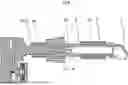
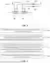
FIG. 1 is a perspective view of an ice making module according to some embodiments of the present disclosure.
FIG. 2 is a front view of an ice making module according to some embodiments of the present disclosure.
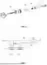
FIG. 3 is a cross-sectional view of portion A-A in FIG. 2.
FIG. 4 is a cross-sectional view of portion B-B in FIG. 2.
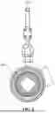
FIG. 5 is a cross-sectional view of portion C-C in FIG. 2.
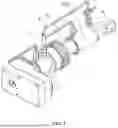
FIG. 6 is an exploded view of an ice making module according to some embodiments of the present disclosure.
FIG. 7 is a schematic diagram of connection of a refrigerant circulation system according to some embodiments of the present disclosure.
FIG. 8 is a schematic diagram of connection of a refrigerant circulation system according to some embodiments of the present disclosure.
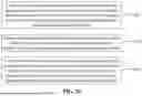
FIG. 9 is a flowchart of operations of an ice making method according to some embodiments of the present disclosure.
FIG. 10 is a flowchart of operations of an ice making method according to some embodiments of the present disclosure.
DETAILED DESCRIPTION
In order to make the objectives, technical solutions, and advantages of the present disclosure clearer, the present disclosure will be further described in detail below with reference to the accompanying drawings and embodiments. It should be understood that the specific embodiments described herein are merely used to explain the present disclosure, but are not used to limit the present disclosure.
Various specific technical features described in the specific embodiments may be combined with each other in any suitable manner as long as there is no contradiction. For example, different embodiments and technical solutions may be formed by combinations of different specific technical features. In order to prevent unnecessary repetition, various possible combinations of specific technical features in the present disclosure are not separately described.
In the following description, the term “first\second\ . . . ” involved is only used to distinguish different objects, and does not indicate that the objects have the same or related parts. It should be understood that the orientation descriptions “above”, “below”, “outer”, and “inner” involved are all orientations in a normal use state, and the “left” and “right” directions represent the left and right directions shown in the specific corresponding schematic diagrams, which may or may not be the left and right directions in the normal use state.
It should be noted that the terms “comprising”, “including”, or any other variation thereof are intended to indicate non-exclusive inclusion, so that processes, methods, articles, or devices including a series of elements not only include those elements, but also include other elements not explicitly listed, or further include elements inherent to such processes, methods, articles, or devices. In the absence of more limitations, an element defined by the statement “comprising a . . . ” does not preclude the presence of additional equivalent elements in a process, method, article, or device that includes the element. “A plurality” means two or more.
Some embodiments of the present disclosure provide an ice making module. As shown in FIGS. 1 to 3, the ice making module includes an ice making assembly 1, an ice discharge channel 2, and a cold source 3. The ice making assembly 1 is configured to make and output a plurality of ice pieces with a first specification. It should be noted that the type of configuration of the ice making assembly 1 is not limited in the embodiments of the present disclosure. For example, a plurality of shaped ice outlets 11 may be provided within one ice making assembly 1, each shaped ice outlet 11 outputs one ice piece with the first specification, and the plurality of shaped ice outlets 11 may output a plurality of ice pieces with the first specification. Certainly, a plurality of ice making assemblies 1 may be provided, and each ice making assembly 1 is provided with one shaped ice outlet 11. In this way, the plurality of ice making assemblies 1 are provided with a plurality of shaped ice outlets 11, and the plurality of ice making assemblies 1 can output a plurality of ice pieces with the first specification. That is, regardless of the configuration form of the ice making assembly 1, it is sufficient as long as a plurality of ice pieces with the first specification can be made and outputted.
In the embodiments of the present disclosure, an example in which one ice making assembly 1 is provided with a plurality of shaped ice outlets 11 is used for description. The shaped ice outlets 11 are configured to output the ice pieces with the first specification. An ice piece with the first specification refers to a shaped ice piece with a certain appearance shape, which may be an elongated ice piece, an ice block, etc. The shapes or dimensions of the ice pieces with the first specification outputted from the plurality of shaped ice outlets 11 may be the same or different. The ice piece with the first specification may be understood as a small ice piece with a small volume.
It should be noted that, with reference to FIG. 4, the number of shaped ice outlets 11 provided within the ice making assembly 1 is not limited in the embodiments of the present disclosure. The number of shaped ice outlets 11 may be set to be two, three, four, five, etc., and the number of shaped ice outlets 11 may be set according to specific product function requirements. In the embodiments of the present disclosure, a plurality of shaped ice outlets are provided within the ice making assembly 1, so that the ice making assembly 1 can output a plurality of ice pieces with the first specification at one time, thereby improving the efficiency of ice discharge.
As shown in FIG. 3, an end of the ice discharge channel 2 is in communication with the ice making assembly 1, and the ice discharge channel 2 is configured to receive the plurality of ice pieces with the first specification from the plurality of shaped ice outlets 11. The ice discharge channel 2 is provided with a freezing region 21. The cold source 3 is disposed in the freezing region 21 of the ice discharge channel 2 and is configured to supply cooling capacity to the freezing region 21 during cooling, to allow the plurality of ice pieces with the first specification passing through the freezing region 21 to be frozen into a one-piece ice structure. That is, the ice making assembly 1 outputs a plurality of small shaped ice pieces with the first specification to the ice discharge channel 2 through the plurality of shaped ice outlets 11 at one time, and the plurality of small shaped ice pieces with the first specification located in the freezing region 21 are frozen into a whole large ice piece with a second specification under the action of the cooling capacity. The large ice piece represents a shaped ice piece with a larger volume, and the volume of the large ice piece is approximately equal to the sum of the volumes of the plurality of small ice pieces, that is, the second specification is approximately equal to the sum of the plurality of first specifications. The plurality of small ice pieces with the first specification within the freezing region 21 may be frozen into a large one-piece ice piece with the second specification. Therefore, the ice discharge channel 2 can output shaped ice pieces with a larger volume.
The cooling capacity described in the embodiments of the present disclosure means that the cold source 3 is used to achieve thermal field changes of the shaped ice pieces in the freezing region. The cold source 3 supplies the cooling capacity to the freezing region 21, and the cold source 3 absorbs heat within the freezing region 21, thereby taking away heat of the shaped ice pieces with a smaller volume, so that the small ice pieces closely attached to each other are frozen and bonded to each other to form a shaped ice piece with a larger volume. In the embodiments of the present disclosure, shaped ice pieces with different sizes can be provided by using changes in the thermal field. Compared with the method of cutting large ice pieces using a cutter, energy consumed for cutting is saved, and wear of the cutter is also prevented. Compared with the method of using mechanical energy to compress small ice pieces into large ice pieces, the consumption of mechanical energy is reduced, and the cumbersome operation of mold head switching is prevented.
The sizes of the large ice piece and the small ice piece described in the embodiments of the present disclosure are only used as a relative schematic comparison in the same product. That is, the volume of the large ice piece is greater than the volume of the small ice piece in the same electrical appliance, but the absolute value of the volume of the small ice piece or the large ice piece is not specifically limited. In other words, in different products, the absolute value of the volume of the small ice piece in one product may be greater than the absolute value of the volume of the large ice piece in another product.
Some embodiments of the present disclosure provide an ice making module. The ice making module includes an ice making assembly, an ice discharge channel, and a cold source. The ice making assembly is configured to make and output a plurality of ice pieces with a first specification. An end of the ice discharge channel is in communication with the ice making assembly. The ice discharge channel is configured to receive the plurality of ice pieces with the first specification. The ice discharge channel is provided with a freezing region. The cold source is configured to supply cooling capacity to the freezing region, to allow the plurality of ice pieces with the first specification passing through the freezing region to be frozen to form an ice piece with a second specification. In the embodiments of the present disclosure, a plurality of shaped ice pieces with a smaller volume are outputted to the ice discharge channel at one time by the ice making assembly. The ice discharge channel is provided with the freezing region, and the cold source can provide the cooling capacity to the freezing region, to allow the plurality of shaped ice pieces with the smaller volume to be frozen into a one-piece shaped ice piece with a larger volume. The same ice making module can achieve the output of multiple shaped ice pieces with different specifications, and the output of large ice pieces and small ice pieces is achieved through adjustments in the thermal field. The operation has high stability, and ice blocks are regularly shaped, thereby reducing apparatus consumables and reducing the consumption of mechanical energy. Reliability is high and noise is low, thereby improving the user experience.
It should be noted that a manner of operation of the cold source is not limited in the embodiments of the present disclosure, that is, the cold source is disposed in the freezing region of the ice discharge channel, so that the cold source can have the function of supplying cooling capacity to the freezing region. However, this does not mean that the cold source and the ice making module have synchronous and continuous operating states. Specifically, the ice making assembly has a first ice making state and a second ice making state, and the cold source may have a working state and a non-working state. When the cold source is in the working state, the cold source can supply cooling capacity to the freezing region, so that the ice making module can output shaped ice pieces with a larger volume. This state is the second ice making state of the ice making assembly. When the cold source is in the non-working state, the cold source does not supply cooling capacity to the freezing region, and the ice making module directly outputs a plurality of shaped ice pieces with a smaller volume outputted from the plurality of ice outlets. This state is the first ice making state of the ice making assembly.
In the embodiments of the present disclosure, the ice making assembly has a greater ice making cooling capacity in the first ice making state than in the second ice making state. It should be noted that the magnitude of the ice making cooling capacity affects the water content of the ice pieces made by the ice making assembly. The smaller the ice making cooling capacity, the higher the water content of the ice pieces made by the ice making assembly. The greater the ice making cooling capacity, the lower the water content of the ice pieces made by the ice making assembly. In the embodiments of the present disclosure, the ice making cooling capacity in the first ice making state is greater than the ice making cooling capacity in the second ice making state. That is, the ice pieces made in the first ice making state have a lower water content than the ice pieces made in the second ice making state. The ice pieces with the first specification made in the first ice making state may be directly outputted for use by a user. Therefore, the ice pieces made in the first ice making state have a lower water content, which facilitates improvement of the user experience. The ice pieces with the first specification made in the second ice making state are used for freezing into the ice piece with the second specification in the freezing region. Therefore, the ice pieces made in the second ice making state have a high water content, which facilitates the release of heat from water and the freezing of water into ice, thereby facilitating the freezing of the ice pieces with the first specification into the ice piece with the second specification, and further improving the stability of the ice piece with the second specification.
In some embodiments, as shown in FIGS. 1 and 3, the cold source 3 is disposed to surround a circumferential direction of the freezing region 21. The freezing region represents a space for accommodating the first specification. The cold source 3 surrounding the freezing region means that the cold source 3 is disposed around the outside of the freezing region 21. By disposing the cold source 3 in a surrounding manner, improvement of the uniformity of the supplied cooling capacity within the freezing region is facilitated, thereby facilitating improvement of the stability of the plurality of ice pieces with the first specification freezing into one piece within the freezing region.
In some embodiments, as shown in FIGS. 1 to 3, the ice making assembly 1 outputs an ice block with a first specification from each shaped ice outlet 11. It should be noted that the first specification includes, but is not limited to, a cross-sectional shape, a cross-sectional area size, etc., of the shaped ice piece. The first specifications of the plurality of shaped ice outlets 11 in the ice making assembly 1 may be the same or different, and the ice pieces with the first specifications output from different shaped ice outlets 11 may be set according to the product requirements of the electrical appliance.
In some embodiments of the present disclosure, the ice pieces of the plurality of shaped ice outlets 11 are arranged in groups. In some embodiments, adjacent surface shapes between ice pieces discharged from the plurality of shaped ice outlets 11 may be matched to each other to allow a plurality of ice pieces in the same group to be frozen into an ice piece with a second specification in the freezing region 21 during cooling, to improve the structural stability of the ice piece with the second specification. It should be noted that “during cooling” in the above-described embodiments refers to the adjustment of the operation of the cold source 3 in the freezing region. That is, the cold source 3 supplies cooling capacity to the freezing region only when required, and making and discharging shaped ice pieces with different specifications can be achieved by controlling the working state of the cold source 3. This control method is stable and convenient. In some embodiments, an ice breaking structure does not need to be provided for the ice blocks discharged from the ice discharge channel.
For example, there are four shaped ice outlets 11, and each time, four ice pieces may be frozen as a group, or eight ice pieces may be frozen as a group, and so on.
In some embodiments, as shown in FIG. 3, the ice making assembly 1 outputs an ice piece with a first specification from each shaped ice outlet 11. As shown in FIG. 5, the freezing region 21 is configured to freeze the plurality of ice pieces into the ice piece with the second specification during cooling. The second specification is greater than the first specification, and the dimension may be understood as the cross-sectional area of the ice piece, the shape or volume of the ice piece, or the like.
As shown with reference to FIGS. 1 to 3, the ice making module includes an ice breaking structure 4. The ice breaking structure 4 is disposed at an end of the ice discharge channel 2, and the end of the ice discharge channel 2 represents an end of the ice discharge channel 2 away from the shaped ice outlets 11. The ice breaking structure 4 is configured to break an elongated ice piece discharged from the ice discharge channel 2 to obtain ice blocks. That is, the elongated ice piece may be understood as a strip-shaped ice piece with a certain length, and ice blocks with a shorter length may be obtained after the elongated ice piece is broken. The specific ice breaking manner of the ice breaking structure 4 is not limited in the embodiments of the present disclosure, as long as the ice breaking structure 4 can break the elongated ice piece, which is a long strip, into a plurality of shorter ice blocks. The length of the ice blocks broken by the ice breaking structure 4 is not limited in the embodiments of the present disclosure.
In some embodiments, as shown in FIG. 3, the ice discharge channel 2 extends in a straight line, and the ice breaking structure 4 bends from the end of the ice discharge channel 2 to a side of the ice discharge channel 2. That is, an ice breaking channel is provided inside the ice breaking structure 4, the ice breaking channel (ice breaking structure) extends in an arc direction, an end of the ice breaking channel is in communication with the ice discharge channel 2, and another end of the ice breaking channel is configured to discharge the broken ice blocks. The arc direction means that an inner surface of the ice breaking structure 4 gradually changes according to a certain curvature, so that the inside of the ice breaking channel is arranged in a curved manner. The elongated ice piece within the ice discharge channel 2 moves to the ice breaking channel along an extension direction of the ice discharge channel. When an end of the elongated ice piece comes into contact with a wall surface of the ice breaking channel, a driving force drives the elongated ice piece to continuously move in the direction of pressing against the wall surface of the ice breaking structure. Since the elongated ice piece has high rigidity and is prone to breaking, the elongated ice piece is broken within the ice breaking structure under the action of a pressing force.
In the above-described embodiments of the present disclosure, an ice breaking test of the ice breaking structure in some of the above embodiments was performed, and after testing and verification, the elongated ice piece was broken when bent by approximately 11°, and it was manually verified that the success rate of ice breaking was high. Moreover, large ice blocks broken by the ice breaking structure still retained the shape of the large ice piece, and the fracture surfaces were flat. Small ice blocks broken at a bending end still retained the shape of the small ice pieces, without adhesion, and the fracture surfaces were flat.
In the embodiments of the present disclosure, by providing the bent ice breaking structure, the manner of ice block breaking can be simple and quick, and the quality of ice block breaking can be high, so that no additional cutting tools are required, thereby reducing product consumables and costs.
The specific type of the cold source 3 is not limited. For example, in some embodiments, the cold source 3 may be a cold end of a thermoelectric cooler. Specifically, the ice making module includes a control circuit, the thermoelectric cooler is connected to the control circuit, and the control circuit may control the cold end of the thermoelectric cooler to provide cooling capacity to a region.
In some embodiments, as shown in FIGS. 7 and 8, the ice making module includes a refrigerant circulation system 5. The refrigerant circulation system 5 includes a compressor, a condenser, a throttling member, and a first evaporator 51. The compressor, the condenser, the throttling member, and the first evaporator 51 are sequentially disposed in a refrigerant flow direction, and the first evaporator is the cold source 3. In FIGS. 7 and 8, the direction denoted by the solid arrows indicates a flow direction of a refrigerant in the refrigerant circulation system, and the direction denoted by the dashed arrows indicates a movement direction of water or ice. That is, the first evaporator 51 is configured to provide cooling capacity to the freezing region to achieve the freezing of small ice pieces within the freezing region.
In some embodiments, as shown in FIG. 3, the cold source 3 surrounds an outer periphery of a first tubular structure 6. The refrigerant in the cold source 3 is configured to exchange heat with a substance within the ice discharge channel 2 in the first tubular structure 6. The relative position of the cold source 3 and the first tubular structure 6 may be adjusted as needed. For example, the cold source 3 may be disposed on an outer peripheral side of the first tubular structure 6 as shown in FIG. 3, or the first tubular structure 6 may also be disposed on an outer peripheral side of the cold source 3.
In some embodiments, as shown in FIGS. 7 and 8, the first evaporator 51 includes a first refrigerant circuit, and the first refrigerant circuit surrounds an outer peripheral side of the ice discharge channel. In the embodiments of the present disclosure, the first refrigerant circuit is disposed around the outer peripheral side of the ice discharge channel, so that the first refrigerant circuit can directly exchange heat with the ice discharge channel, which facilitates improvement of ice making efficiency, and further facilitates improvement of the uniformity of the supplied cooling capacity within the ice discharge channel, thereby facilitating improvement of the quality of the shaped ice pieces within the ice discharge channel.
In some embodiments, as shown in FIGS. 7 and 8, the refrigerant circulation system 5 includes a second evaporator 52, and the second evaporator supplies cooling capacity to the ice making assembly 1. That is, the second evaporator supplies the cooling capacity to the ice making assembly 1, the second evaporator is disposed at the ice making assembly, and when water enters the ice making assembly, the second evaporator 52 exchanges heat with the ice making assembly 1 to reduce the temperature inside the ice making assembly, so that the water is solidified into ice. In some embodiments, the same refrigerant circulation system 5 can provide cooling capacity for both the ice discharge channel 2 and the ice making assembly 1, which can make the structure compact. In addition, when the cold source is not required to provide cooling capacity, the refrigerant does not flow through the first evaporator at this time. However, since the second evaporator needs to continuously supply cooling capacity to the ice making assembly, the refrigerant may continue to circulate in the refrigerant circulation system, and the compressor does not need to be frequently started or shut down.
In some embodiments, as shown in FIG. 7, the present embodiments provides a first type of refrigerant circulation system.
In FIG. 7, the direction denoted by the solid arrows indicates the flow direction of the refrigerant, and the direction denoted by the dashed arrows indicates the movement direction of water or ice. The refrigerant circulation system 5 includes a first branch 53 and a second branch 54, a first end of the first branch 53 is connected to a first end of the second branch 54, the first evaporator 51 is disposed on the first branch 53, and a second end of the second branch 54 and a second end of the first branch 53 are connected to an inlet of the second evaporator 52. The refrigerant circulation system 5 further includes a valve device 55, and the valve device 55 is configured to allow flow through or close off the first branch 53. It can be understood that the ice making assembly in the refrigerant circulation system in the embodiments of the present disclosure has a first ice making state and a second ice making state, and the second evaporator has a greater ice making cooling capacity in the first ice making state than in the second ice making state.
In the second ice making state, the valve device 55 allows flow through the first branch 53, so that the refrigerant can flow to the first branch 53. The flow path of the refrigerant is: the valve device 55—the first branch 53—the first evaporator 51—the second evaporator 52. Small ice pieces made by the second evaporator in the second ice making mode have a certain water content. When a plurality of small ice pieces pass through the ice discharge channel, the first evaporator 51 absorbs the heat of the water on the small ice pieces again, and the plurality of small ice pieces are frozen into a large one-piece ice piece.
In the first ice making state, the valve device 55 closes off the first branch 53, so that the refrigerant cannot flow to the first branch 53, but flows to the second branch 54. The flow path of the refrigerant is: the valve device 55—the second branch 54—the second evaporator 52. Since the cold source does not pass through the first evaporator 51, the plurality of small ice blocks passing through the ice discharge channel will not be frozen into a large ice piece. Therefore, the shaped ice pieces made by the ice making module are small ice pieces.
In some embodiments, as shown in FIG. 7, the valve device includes a first state and a second state. In the first state, the valve device closes off the first branch 53 and allows flow through the second branch 54. In the second state, the valve device allows flow through the first branch 53 and closes off the second branch 54, to allow the first evaporator and the second evaporator to be connected in series. In the first state, a first switch 531 closes off the first branch 53, and a second switch 541 allows flow through the second branch 54, so that the refrigerant flows from the second branch 54 to the second evaporator 52 without flowing to the first evaporator 51, thereby achieving the function of outputting small ice pieces by the ice making module. In the second state, the first switch 531 allows flow through the first branch 53, and the second switch 541 closes off the second branch 54, so that the refrigerant first flows to the first evaporator 51 and then flows to the second evaporator 52, thereby making large ice pieces.
In some embodiments, as shown in FIG. 8, the embodiments provide a second type of refrigerant circulation system. In FIG. 8, the direction denoted by the solid arrows indicates the flow direction of the refrigerant, and the direction denoted by the dashed arrows indicates the movement direction of water or ice. The valve device includes a first state and a second state. The valve device may include a first switch 531 and a second switch 541. The first switch 531 is configured to allow flow through and close off the first branch 53, and the second switch 541 is configured to allow flow through and close off the second branch 54. That is, in the embodiments of the present disclosure, two switches may be provided separately to independently control the flow-allowed and closed off states of the first branch and the second branch, so that the first evaporator and the second evaporator are connected in parallel. It should be noted that the first switch and the second switch in the embodiments of the present disclosure may be configured as electronic expansion valves, and the control manner is stable.
In the first state, the first switch 531 is open, the second switch 541 is closed, and the refrigerant flows only to the first evaporator 51, thereby achieving the discharge of small ice pieces. In the second state, the first switch 531 and the second switch 541 are open, and the refrigerant separately flows to the first evaporator 51 and the second evaporator 52, to achieve the discharge of large ice pieces.
In some embodiments, with reference to FIGS. 3 and 4, the ice making module includes the first tubular structure 6. The ice making assembly includes an ice mold 12. The shaped ice outlets 11 are disposed on the ice mold 12. The ice mold 12 is disposed inside the first tubular structure 6, and a space in the first tubular structure 6 defines at least part of the ice discharge channel 2. It should be noted that the ice mold in the embodiments of the present disclosure is configured to form a plurality of small ice pieces with the first specification, and each shaped ice outlet discharges one shaped ice piece with a small volume.
In some embodiments, the ice mold 12 includes a plurality of blades. The plurality of blades are connected to each other at one end and form a radial distribution. The shaped ice outlets are formed between any two adjacent blades. The plurality of blades extend to an inner wall of the ice discharge channel at another end. The first tubular structure 6 first makes a shaped ice piece, and then the shaped ice piece is divided into a plurality of ice pieces with a first specification by the plurality of blades.
In some embodiments, as shown in FIG. 3, the ice making assembly 1 includes an ice making cavity 13 and an ice scraping screw 14. The ice scraping screw 14 is at least partially disposed within the ice making cavity 13, and the ice scraping screw 14 is configured to scrape ice within the ice making cavity 13 to obtain ice shavings, and to convey the scraped ice shavings to the shaped ice outlets. The ice scraping screw 14 may only be partially located within the ice making cavity 13, or may be entirely disposed within the ice making cavity 13. The ice scraping screw 14 may scrape the frozen ice within the ice making cavity 13 into ice shavings through the rotation of the ice scraping screw 14, and the ice shavings are conveyed to the first tubular structure 6 under the pushing of the ice scraping screw 14.
As shown in FIG. 3, an axis of rotation of the ice scraping screw 14 may extend in a transverse direction, a water inlet is located on one of two opposite sides of the ice making cavity 13 in the transverse direction, and the shaped ice outlets are located on another one of the two opposite sides of the ice making cavity 13 in the transverse direction. That is, water flows into the ice making cavity 13 from one side of the ice making cavity 13 in the transverse direction, and the ice shavings scraped off by the ice scraping screw 14 are discharged from another side of the ice making cavity 13 in the transverse direction, which is equivalent to the second evaporator being disposed in the transverse direction.
With reference to FIG. 3, the ice making module is provided with a driving assembly, and the driving assembly is configured to drive the ice scraping screw to rotate.
The ice shavings scraped off by the ice scraping screw 14 are compacted and shaped in the ice making cavity 13 to form an elongated ice piece.
It should be noted that the elongated ice piece is not an ice block, and the elongated ice piece is broken to become ice blocks.
As shown in FIG. 4, the ice mold 12 including shaping channels with at least two different cross sections means that the ice mold 12 may include shaping channels with two different cross sections, or may include shaping channels with two or more different cross sections. The different cross sections mean that the cross sections of the shaping channels are different in at least one of the shape or the dimension. For example, the shape of the cross section of one shaping channel is rectangular, and the shape of the cross section of another shaping channel is circular. Alternatively, the shapes of the cross sections of two shaping channels are both rectangular, but the dimension of the cross section of one shaping channel is greater than the dimension of the cross section of another shaping channel.
The shape of the elongated ice piece corresponds to the cross section of the shaping channel, that is, the shaping channels with different cross sections can respectively make elongated ice pieces with different shapes.
In some embodiments, with reference to FIG. 6, the first tubular structure 6 and the ice making cavity 13 are coaxially disposed. By making the first tubular structure 6 be coaxial with the ice making cavity 13, smooth conveying of the shaped ice pieces generated by the first tubular structure 6 to the ice making cavity 13 is facilitated, thereby improving the stability of the movement of the shaped ice pieces, and further improving the stability of subsequent connection of the shaped ice pieces within the ice making cavity 13.
In some embodiments, as shown in FIG. 3, the first tubular structure 6 and the ice making cavity 13 are butt-joined along the length direction. The length direction in FIG. 3 indicates the left-right direction of the paper surface. With reference to FIG. 3, the first tubular structure 6 and the ice making cavity 13 are butt-joined along the length direction, so that the movement direction of the shaped ice pieces in the first tubular structure 6 is consistent with the movement direction of the shaped ice pieces in the ice making cavity 13, which facilitates improvement of the freezing stability of the shaped ice pieces.
The embodiments of the present disclosure further provide an electrical appliance, including the ice making module described in any one of the embodiments described above. The electric appliance includes, but is not limited to, a refrigerator, an ice maker, a blender, and other electric appliances. The application scenario of the electrical appliance does not limit the structure of the ice making module in the embodiments of the present disclosure.
The embodiments of the present disclosure further provide an ice making method.
As shown in FIG. 9, the ice making method includes the following operations.
At operation S101, an ice making assembly is controlled to make ice to obtain a plurality of small elongated ice pieces.
At operation S102, the plurality of small elongated ice pieces are conveyed to an ice discharge channel, in which the ice discharge channel is provided with a freezing region, and the freezing region is provided with a cold source.
At operation S103, the cold source is controlled to be in a cooling state or a non-cooling state according to an ice making instruction, in which in case that the cold source is in the cooling state, the freezing region is configured to freeze the plurality of small elongated ice pieces passing through the freezing region into a large one-piece elongated ice piece.
At operation S104, the elongated ice piece discharged from the ice discharge channel is broken to obtain ice blocks.
In the embodiments of the present disclosure, the cold source is controlled to be in the cooling state or the non-cooling state according to the ice making instruction. In case that the cold source is in the cooling state, the freezing region is configured to freeze the plurality of small elongated ice pieces passing through the freezing region into the large one-piece elongated ice piece. That is, whether to make a large elongated ice piece can be directly controlled by controlling whether the freezing region is in the cooling state. The control manner is simple and convenient, and the output of large ice pieces and small ice pieces is achieved through adjustments in the thermal field. The operation method has high stability, and ice blocks are regularly shaped, thereby reducing apparatus consumables and reducing the consumption of mechanical energy. Reliability is high and noise is low, thereby improving the user experience.
The embodiments of the present disclosure further provide an ice making method.
As shown in FIG. 10, the ice making method includes the following operations.
At operation S201, an ice making assembly is controlled to make ice to obtain a plurality of groups of small ice blocks, in which each group of small ice blocks includes a plurality of small ice blocks, and any two adjacent groups of the plurality of groups of small ice blocks are spaced apart from each other in a conveying direction.
At operation S202, the plurality of groups of small ice blocks are conveyed to an ice discharge channel, in which the ice discharge channel is provided with a freezing region, and the freezing region is provided with a cold source.
At operation S203, the cold source is controlled to be in a cooling state or a non-cooling state according to an ice making instruction, in which in case that the cold source is in the cooling state, the freezing region is configured to freeze the same group of the plurality of groups of small ice blocks passing through the freezing region into a large one-piece ice block.
In the embodiments of the present disclosure, the cold source is controlled to be in the cooling state or the non-cooling state according to the ice making instruction. In case that the cold source is in the cooling state, the freezing region is configured to freeze the plurality of small ice blocks passing through the freezing region into the large one-piece ice block. That is, whether to make a large ice block can be directly controlled by controlling whether the freezing region is in the cooling state. The control manner is simple and convenient, and the output of the large ice pieces and the small ice pieces is achieved through adjustments in the thermal field. The operation method has high stability, and ice blocks are regularly shaped, thereby reducing apparatus consumables and reducing the consumption of mechanical energy. Reliability is high and noise is low, thereby improving the user experience.
In the description of the present disclosure, the description with reference to the terms “one embodiment,” “some embodiments,” “an example,” “an specific example,” “some examples,” etc., means that the specific features, structures, materials, or characteristics described in combination with the embodiment(s) or example(s) are included in at least one embodiment or example of the embodiments of the present disclosure. In the present disclosure, schematic representations of the above-described terms do not necessarily refer to the same embodiment or example. Moreover, the specific features, structures, materials, or characteristics described may be combined in any one or more embodiments or examples in a suitable manner. In addition, those skilled in the art may combine different embodiments or examples described in the present disclosure and features of different embodiments or examples without contradicting each other.
The above-described description is only preferred embodiments of the present disclosure and is not intended to limit the present disclosure, and for those skilled in the art, the present disclosure may have various modifications and changes. Any modifications, equivalent substitutions, improvements, etc., made within the spirit and principle of the present disclosure should be encompassed within the scope of protection of the present disclosure.
Claims
1. An ice making module, comprising:
an ice making assembly configured to make and output a plurality of ice pieces with a first specification;
an ice discharge channel, an end of the ice discharge channel being in communication with the ice making assembly, the ice discharge channel being configured to receive the plurality of ice pieces with the first specification, and the ice discharge channel being provided with a freezing region; and
a cold source configured to supply cooling capacity to the freezing region, to allow the plurality of ice pieces with the first specification passing through the freezing region to be frozen to form an ice piece with a second specification, a volume of each ice piece with the first specification being less than a volume of the ice piece with the second specification.
2. The ice making module according to claim 1, wherein the ice making assembly has a first ice making state and a second ice making state, and the cold source has a working state and a non-working state; in case that the cold source is in the non-working state, the ice making assembly is in the first ice making state, and in case that that the cold source is in the working state, the ice making assembly is in the second ice making state, the ice making assembly having a greater ice making cooling capacity in the first ice making state than in the second ice making state.
3. The ice making module according to claim 1, wherein the cold source surrounds a circumferential direction of the freezing region.
4. The ice making module according to claim 1, further comprising a control circuit, wherein the cold source comprises a thermoelectric cooler connected to the control circuit, and the thermoelectric cooler is provided with a cold end configured to supply cooling capacity to the freezing region.
5. The ice making module according to claim 1, further comprising a refrigerant circulation system, wherein the refrigerant circulation system comprises a compressor, a condenser, a throttling member, and a first evaporator, and the first evaporator is the cold source.
6. The ice making module according to claim 5, wherein the first evaporator comprises a first refrigerant circuit, and the first refrigerant circuit surrounds an outer peripheral side of the ice discharge channel.
7. The ice making module according to claim 5, wherein the refrigerant circulation system comprises a second evaporator, and the second evaporator supplies cooling capacity to the ice making assembly.
8. The ice making module according to claim 7, wherein the refrigerant circulation system comprises a first branch, a second branch, and a valve device, and the valve device is configured to allow flow through or close off the first branch and the second branch.
9. The ice making module according to claim 8, wherein a first end of the first branch is connected to a first end of the second branch, the first evaporator is disposed on the first branch, and a second end of the second branch and a second end of the first branch are connected to an inlet of the second evaporator; and
the valve device is configured to close off the first branch and allow flow through the second branch, or allow flow through the first branch and close off the second branch, to allow the first evaporator and the second evaporator to be connected in series.
10. The ice making module according to claim 8, wherein the first branch and the second branch are connected in parallel, the first evaporator is disposed on the first branch, the second evaporator is disposed on the second branch, and the valve device is configured to allow flow through or close off the first branch, and allow flow through or close off the second branch.
11. The ice making module according to claim 1, further comprising a first tubular structure, wherein the ice making assembly comprises an ice mold provided with a plurality of shaped ice outlets, the ice mold is disposed inside the first tubular structure, a space in the first tubular structure defines at least part of the ice discharge channel, and the plurality of shaped ice outlets are configured to output the plurality of ice pieces with the first specification.
12. The ice making module according to claim 11, wherein the ice making assembly comprises an ice making cavity and an ice scraping screw, the ice scraping screw is at least partially disposed within the ice making cavity, and the ice scraping screw is configured to scrape ice on an inner wall of the ice making cavity to obtain ice shavings, and convey the scraped ice shavings to the first tubular structure.
13. The ice making module according to claim 11, wherein the ice mold comprises blades, and the blades cut ice in the first tubular structure into the plurality of ice pieces with the first specification.
14. An electrical appliance, comprising the ice making module according to claim 1.
Images & Drawings included:


Sources:
- United States Patent and Trademark Office - verify current appl. status at the USPTO↗
Recent applications in this class:
- » 20260016209 2026-01-15
ICEMAKER APPLIANCE AND METHOD FOR OPERATION TO PREVENT FROZEN AUGER - » 20260002719 2026-01-01
Ice-making method, ice-making apparatus, storage medium, and computer program product - » 20260002718 2026-01-01
ICE-MAKING METHOD, ICE-MAKING APPARATUS, STORAGE MEDIUM, AND COMPUTER PROGRAM PRODUCT - » 20260002717 2026-01-01
ICE-MAKING METHOD, ICE-MAKING APPARATUS, STORAGE MEDIUM, AND COMPUTER PROGRAM PRODUCT - » 20250383135 2025-12-18
ICE-MAKING ASSEMBLY AND ICE-MAKING DEVICE - » 20250334312 2025-10-30
ICE-MAKING SYSTEM, WHICH CONTROLS ICE HARDNESS - » 20250180266 2025-06-05
ICEMAKER APPLIANCE - » 20250085041 2025-03-13
INDICATOR LIGHTS IN STAND-ALONE ICE MAKING APPLIANCE - » 20250067488 2025-02-27
Method of operating a BLDC motor in an ice making appliance - » 20250052468 2025-02-13
COUNTERTOP ICE MAKER APPLIANCE AND METHODS OF OPERATING THE SAME