TEMPERATURE-CONTROLLED ENCLOSURE WITH CLEAR MULLION
US20260053280A1
2026-02-26
18/812,805
2024-08-22
Smart Summary: A new type of mullion is designed for temperature-controlled spaces, like refrigerators or freezers. It has a clear front part that allows people to see inside without opening the door. This clear section also has special surfaces that help keep the temperature stable. The mullion is strong enough to support the structure while maintaining visibility. Overall, it combines functionality with transparency for better user experience. 🚀 TL;DR
Abstract:
A mullion for a temperature-controlled enclosure. The mullion includes a transparent front-facing portion and a load-bearing portion. The transparent front-facing portion defines one or more scaling surfaces.
Inventors:
- Mark Sandnes 17 🇺🇸 Granada Hills, CA, United States
- Pedro Almaguer 15 🇺🇸 North Hills, CA, United States
- Sai Prakash Putti 2 🇺🇸 Moorpark, CA, United States
Applicant:
Interested in similar patents?
Get notified when new applications in this technology area are published.
Classification:
A47F3/0434 » CPC main
Show cases or show cabinets air-conditioned, refrigerated; Cases or cabinets of the closed type; Details Glass or transparent panels
A47F3/04 IPC
Show cases or show cabinets air-conditioned, refrigerated
Description
TECHNICAL FIELD
The present disclosure relates to temperature-controlled storage devices, doors, and associated frames used in such devices.
BACKGROUND
Refrigerated enclosures are used in commercial, institutional, and residential applications for storing and/or displaying refrigerated or frozen objects. Refrigerated enclosures may be maintained at temperatures above freezing (e.g., a refrigerator) or at temperatures below freezing (e.g., a freezer). Refrigerated enclosures have one or more doors or windows for accessing and viewing refrigerated or frozen objects within a temperature-controlled space. Refrigerated enclosures typically include a frame that supports the doors or windows.
Condensation on sealing surfaces of doors of refrigerated enclosures and their associated frames can impair sealing and decrease energy efficiency. Formation of condensation (or frost formation) on a door also affects visibility to product placed inside enclosure and may cause customer dissatisfaction. Electric heater wires are sometimes employed in the thermal frames of commercial refrigerated enclosures to inhibit condensation. However, electrical heaters can use a significant amount of electrical power. Excess reliance on such heater wires may make ever more stringent government regulations on energy efficiency more difficult to meet.
SUMMARY
The present disclosure relates to temperature-controlled storage devices, and doors and associated frames used in such devices. Some implementations include a mullion for a temperature-controlled enclosure. The mullion includes a transparent front-facing portion and a load-bearing portion. The transparent front-facing portion defining one or more sealing surfaces.
In some implementations, the mullion has a body having a rectangular tubular shape. At least a forward-facing wall of the body is transparent.
In some implementations, the mullion has a body defines a U-shape. The mullion includes a transparent-front-facing portion and a pair of opposing side walls.
In some implementations, the mullion extends between an upper frame portion of the temperature-controlled enclosure and a lower frame portion of the temperature-controlled enclosure.
In some implementations, the load-bearing portion bears a portion of a weight of the upper frame portion of the temperature-controlled enclosure.
In some implementations, the mullion includes a body and a transparent front plate. At least a portion of the body is included in the load-bearing portion. The transparent front plate snaps into the body. The transparent front plate has at least one of the one or more sealing surfaces.
In some implementations, the mullion includes one or more connecting brackets to couple the mullion to a frame of the temperature-controlled enclosure.
In some implementations, the mullion includes a resilient seal to contact one or more surfaces of doors of the temperature-controlled enclosure.
In some implementations, the mullion includes one or more perimeter lights positioned about mullion and coupled to the temperature-controlled enclosure. The perimeter lights illuminate objects in the temperature-controlled enclosure.
In another example implementation, a temperature-controlled enclosure for displaying cold items includes a body, a frame assembly, two or more doors, and one or more mullions. The body has a front opening and defining an interior space of the temperature-controlled enclosure. The frame assembly is coupled in the front opening of the body. The frame assembly has an upper frame portion and a lower frame portion. The two or more doors are coupled to the frame assembly. At least two of the doors include one or more transparent panes. The one or more mullions are coupled to the frame assembly and extend from the upper frame portion and the lower frame portion. Each of at least one of the mullions is between two adjoining ones of the two or more doors. The one or more mullions include a front-facing transparent portion.
In some implementations, the temperature-controlled enclosure includes one or more brackets. Each of at least one of the brackets are coupled between the one or more mullions and the upper frame portion or the lower frame portion.
In some implementations, at least one of the brackets includes a projection that extends into the one or more mullions.
In some implementations, the temperature-controlled enclosure includes one or more lights coupled to the one or more mullions. The one or more lights illuminate objects in the temperature-controlled enclosure.
In some implementations, at least one of the mullions has a load bearing portion to bear a portion of a weight of the upper frame portion of the temperature-controlled enclosure.
In some implementations, the temperature-controlled enclosure includes one or more insulating devices coupled to at least one of the two or more doors to contact the one or more mullions at least when at least one door is closed.
In some implementations, at least one of the insulating devices has a blade.
In some implementations, the temperature-controlled enclosure includes insulating devices on at least one of the two adjoining doors coupled to a sealing surface of at least one of the mullions.
In some implementations, the insulating devices include a resilient blade to engage the sealing surface.
In some implementations, the resilient blade extends at an angle relative a rear surface of the doors.
In some implementations, the insulating device includes a resilient bulb.
In some implementations, the temperature-controlled enclosure includes one or more perimeter lights positioned about mullion and coupled to the temperature-controlled enclosure. The perimeter lights illuminate objects in the temperature-controlled enclosure.
In yet another example implementation, a system for maintaining temperature in a temperature-controlled enclosure includes a door, a mullion, and an insulating device. The door includes one or more transparent panes. The mullion has a transparent front-facing portion. The insulating device resides between the door and the mullion when the door is closed. The insulating device has a transparent blade.
In some implementations, the system includes one or more perimeter lights positioned about mullion and coupled to the temperature-controlled enclosure. The perimeter lights illuminate objects in the temperature-controlled enclosure.
The concepts described herein may provide several advantages. For example, some implementations may provide a more visible merchandising area of a display case. Implementations may provide a frame with improved visibility of the contents of the enclosure in the vertical sections of a door. Implementations may reduce the weight of a display door. Implementations may provide a frame with improved thermal efficiency. Implementations may prevent or minimize condensation build up on door sealing surfaces. Implementations may provide for a more positive thermal seal between adjacent doors of a temperature-controlled enclosure.
The details of one or more implementations of the invention are set forth in the accompanying drawings and the description below. Other features, objects, and advantages of the invention will be apparent from the description and drawings, and from the claims.
DESCRIPTION OF DRAWINGS
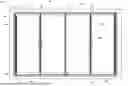
FIG. 1 is a front view of a refrigerated enclosure having multiple doors supported by a frame.
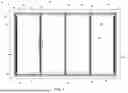
FIG. 2 is a perspective view of the refrigerated enclosure of FIG. 1.
FIG. 3 is a perspective view illustrating a door having an insulated panel assembly with left and right-side guards according to some implementations.
FIG. 4 is a detail view illustrating the relationship between the handle-sides of two adjoining doors at the top of the doors.
FIG. 5 is a top view illustrating a temperature-controlled enclosure having a transparent mullion between two adjoining doors having a first seal with the doors in a closed position.
FIG. 6 is a top view illustrating the transparent mullion of FIG. 5 between two adjoining doors of a temperature-controlled enclosure with the doors in an open position.
FIG. 7 is a top view illustrating the temperature-controlled enclosure of FIGS. 5 and 6 having the transparent mullion between two adjoining doors with a second seal.
FIG. 8 is a top view of another transparent mullion.
FIGS. 9-10 are perspective views of a third transparent mullion.
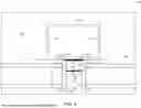
FIG. 11 is rear view of the front-facing portion of the refrigerated enclosure of FIG. 1. from within the refrigerated enclosure.
DETAILED DESCRIPTION
In various implementations, a temperature-controlled enclosure includes a body (e.g., housing), two or more doors having one or more transparent panes, and transparent mullions between the doors. The mullion can provide a scaling surface for insulating devices that are attached to the doors. The mullion can provide structural support (e.g., bearing weight of the portion of the enclosure above the doors and the weight of objects placed on top of the enclosure.
As used herein, “transparent” does not require that all visible light pass through. Transparent does not require that the entire surface be uniform or have uniform transparency or uniform translucency. A transparent element can, for example, be tinted and block some wavelengths of visible light. In some implementations, a transparent element is “fully transparent” in that it permits all wavelengths of visible light to pass through. In some implementations, a transparent element includes a coating. The coating may or may not allow all light to pass through.
In some cases, the coating can protect the transparent element from the environment. In some environments, the conditions of the environment can affect the coating. Placing the coating on the transparent element can increase the life of the transparent element. For example, some transparent elements, when placed in a cold environment for a period of time, the cold environment may cause the transparent element to turning yellow or cloud. The coating can prevent or decrease the degree of yellowing or clouding of the transparent element.
In some implementations, a transparent mullion is made of a polymer or a metal. A transparent mullion can be made of other materials, such as PVC, polycarbonate, polyethylene terephthalate glycol, or glass. In some implementations, a front-facing portion is made of a transparent material, and other parts of the mullion (e.g., side walls) are made of another material. For example, the transparent material can be an acrylic, a polycarbonate, or a glass. However, the transparent material can be any suitable material.
FIG. 1 shows an exemplary refrigerated enclosure 40. FIG. 2 is perspective view of the temperature-controlled enclosure of FIG. 1. Referring to FIGS. 1-2, the refrigerated enclosure 40 may be a refrigerator, freezer, or other enclosure defining a temperature-controlled space. In some implementations, refrigerated enclosure 40 is a refrigerated display case. For example, refrigerated enclosure 40 may be a refrigerated display case or refrigerated merchandiser in grocery stores, supermarkets, convenience stores, florist shops, and/or other commercial settings to store and display temperature-sensitive consumer goods (e.g., food products and the like). Refrigerated enclosure 40 can be used to display products that must be stored at relatively low temperatures and can include shelves, glass doors, and/or glass walls to permit viewing of the products supported by the shelves. In some implementations, refrigerated enclosure 40 is a refrigerated storage unit used, for example, in warehouses, restaurants, and lounges. Refrigerated enclosure 40 can be a free-standing unit or “built in” unit that forms a part of the building in which refrigerated enclosure 40 is located.
Refrigerated enclosure 40 includes a body 42. Body 42 includes a top wall 44, a bottom wall 46, a left-side wall 48, a right-side wall 50, a rear wall (not shown), and a front portion 52 defining a temperature-controlled space. Front portion 52 includes an opening into the temperature-controlled space. Thermal frame 54 can be mounted at least partially within the opening. Thermal frame 54 includes multiple perimeter frame segments (i.e., a header or top frame segment 56, a sill or bottom frame segment 58, a left-side frame segment 60, and a right-side frame segment 62 forming a closed shape along a perimeter of the opening.
Refrigerated enclosure 40 includes doors 64. Each of doors 64 includes an insulated panel assembly 66 and a handle 68. Each of doors 64 is connected to thermal frame 54 by way of an upper hinge 70 and a lower hinge 72. Insulated panel assembly 66 can include one or more panes of glass. In some implementations, insulated panel assembly 66 includes two or more layers of transparent panes bounding a sealed space in between, forming a sealed glass unit (SGU).
In some implementations, the gap or sealed space between two or more panels is filled with an insulating gas such as a noble gas (e.g., argon, krypton, etc.) which functions as a thermal insulator to reduce heat transfer through the panel. In some examples, the sealed space can be evacuated below atmospheric pressure.
Upper hinge 70 and the lower hinge 72 together define pivot axes 74, 76, respectively, about which door 64 swings. Pivot axis 74 and pivot axis 76 can be co-linear. Refrigerated enclosure 40 includes one or more hold-open devices 75 coupled between the doors and the thermal frame 54.
Thermal frame 54 includes transparent mullion 80 and transparent mullion 82 dividing the opening into multiple smaller openings. In this example, refrigerated enclosure 40 includes mullions extending between top frame segment 56 and bottom frame segment 58 to divide the opening into two smaller openings. Each of the smaller openings may correspond to a separate door (or in the example shown in FIG. 2, a separate pair of doors) of the assembly.
Transparent mullion 80 and transparent mullion 82 bear a portion of the weight of the includes a top wall 44. Transparent mullion 80 and transparent mullion 82 can also bear a portion of the weight of loads on top of the enclosure, such as the weight of items placed on top wall 44. The mullions 80, 82 are at least partially transparent to visible light. In some implementations, the mullions 80, 82 are fully transparent. In some implementations, a majority of the length of the mullions 80, 82 is transparent such that the visible light passing through permits a customer to clearly see objects on the other side of the mullion (e.g., products within the enclosure 40) with minimal or no obstruction.
Each of doors 64 includes an insulated panel assembly 66, handle 68, an upper rail 88, and a lower rail 90. Each of the insulated panel assemblies 66 is secured to a corresponding upper rail 88 and a corresponding lower rail 90. Each of doors 64 is connected to the thermal frame by way of the upper hinge 70 and the lower hinge 72.
In FIGS. 1 and 2, the refrigerated enclosure 40 is shown as a four-door assembly with two pairs of doors 64 positioned in an opening in front portion 52. Refrigerated enclosure 40 may have a lesser number of doors 64, or a greater number of doors 64. Applying a force to handle 68 causes the corresponding door 64 to rotate about hinges 70, 72 between an open position and a closed position. In some implementations, insulated panel assembly 66 is a transparent or translucent panel assembly through which items within a temperature-controlled space can be viewed when doors 64 are in the closed position. For example, insulated panel assembly 66 is shown to include multiple transparent or translucent panels with spaces there between. The spaces can be sealed and filled with an insulating gas (e.g., argon) or evacuated to produce a vacuum between the panels. In certain implementations, an insulated panel can include opaque panels with an insulating foam or other insulator there between.
For illustrative purposes. FIG. 2 shows a four-door assembly in which thermal frame 54 includes perimeter frame segments 56, 58, 60, and 62. In other implementations, thermal frame 54 includes a top frame segment and bottom frame segment with no side frame segments. In such implementations, thermal frame 54 can include one or more mullions depending, on the size of the refrigerated enclosure in which thermal frame 54 is to be installed and the number of doors.
In some implementations, a door does not include a dedicated external structural member on one or more of the sides of the doors. For example, a door may omit a rail on the hinge side of the insulated panel assembly, a rail on the handle side of the insulated panel assembly, or both. Some doors described herein may provide increased visibility to the contents of a refrigerated enclosure.
In some implementations, a door system includes side guards on one or more sides of the doors. Side guards can protect the edges of some or all of the panes of an insulated panel assembly. In some implementations, side members also provide (alone or in combination with other elements of the system) thermal insulation and/or sealing between the interior space of the enclosure and the outside environment. Side insulating devices such as described below can be included, for example, on any of the door systems shown in FIGS. 1 through 12.
FIG. 3 is a perspective view illustrating a door having an insulated panel assembly 66 with left and right-side guards according to some implementations. Door 64 includes insulated panel assembly 66, handle 68, hinge-side guard 92, and handle-side guard 94. Hinge-side guard 92 and handle-side guard 94 can run the height of the panes of insulated panel assembly 66.
In various implementations, a door system includes an insulating device between the side of a door and a thermal frame. Components of an insulating device between a door and thermal frame can be secured to the door, the thermal frame, or combination of both. In some implementations, the insulating devices include resilient elements, such as blades (e.g., wipers) that are of made a flexible material.
In various implementations, a door system includes an insulating device between the side of a door and the side of an adjoining door. Components of an insulating device between doors can be secured to one of the doors or combination of both doors. In some implementations, the insulating devices include resilient elements, such as blades (e.g., wipers) that are made of a flexible material.
FIG. 4 is a detail view illustrating the relationship between the handle-sides of two adjoining doors at the top of the doors. Transparent mullion 80 is located behind and between the adjoining edges of doors 64. The doors 64 move between the open position and the closed position. A person desiring to access the interior volume of the refrigerated enclosure 40 can use the handle 68 to one or more of the doors 64 from the closed position to the opened position. The doors 64 contact and seal against the transparent mullion 80 when the doors 64 are in the closed position. The person viewing the contents of the refrigerated enclosure 40 can see through both the doors 64 and the transparent mullion 80, enhancing the visual and shopping experience of the person, and allowing the person to view the product or contents contained within the refrigerated enclosure 40 without requiring opening the doors 64 because the transparent mullion 80 does not interfere and block a portion of the person's line of vision to the contents of the refrigerated enclosure 40. This can also reduce cooling loss when the person may want to closer observe some of the contents while deciding to remove one or more of the contents for later purchase and unnecessarily opening one or more of the doors 64 and subsequently allowing the cooled air in the refrigerated enclosure 40 to escape. Moving the desired door 64 from the closed position to the open position separated the door 64 from the transparent mullion 80 so the person can access the contents of the refrigerated enclosure 40.
FIG. 5 is a top view illustrating a transparent mullion between two adjoining doors of a temperature-controlled enclosure with the doors in a closed position. FIG. 6 is a top view illustrating the transparent mullion of FIG. 5 between two adjoining doors of a temperature-controlled enclosure with the doors in a partially open position. Referring to FIGS. 5 and 6, a temperature controlled enclosure 500 includes two adjoining doors 502 and a transparent mullion 504. In FIG. 5, the doors 502 are in a closed position 526 contacting and scaling against the transparent mullion 504 to prevent cooled air from within the temperature controlled enclosure 500 from exiting the temperature controlled enclosure 500. The doors 502 and door components can also be transparent to visible light, thereby, allowing a person outside the temperature controlled enclosure 500 to view the contents within the temperature controlled enclosure 500. In FIG. 6, the doors 502 of the temperature controlled enclosure 500 are in an intermediate open position 602 (i.e., not yet in a fully open position) and spaced apart from the transparent mullion 80 as the person accessing the interior 506 of the temperature controlled enclosure 500 actuates the doors 502.
The transparent mullion 504 has a front wall 508 defining a front-facing surface 510 oriented toward the doors 502. The transparent mullion 504 has two side walls 512, 514 coupled to the front wall 508, and a back wall 516 opposite the front wall 508. The side walls 512 and 514 are opposite one another. The back wall 516 is coupled between the two side walls 512, 514.
In this implementation, the transparent mullion 504 has a rectangular profile. The transparent mullion 504 supports the weight (i.e., is a load-bearing member extending from a bottom frame segment of the temperature controlled enclosure 500 to a top frame segment of the temperature controlled enclosure 500. The transparent mullion 504 can be a rectangular transparent tube. The transparent mullion 504 can be made from acrylic or other similar material.
A portion of the front-facing surface 510 defines a sealing surface 518. The sealing surface 518 can cover some or all of the front-facing surface 510. The sealing surface 518 is positioned and oriented to receive and contact the doors 502 such that cooled air is prevented from exiting the interior 506 of the temperature controlled enclosure 500 when the doors 502 are in the closed position 526. In this implementation, the sealing surface 518 is a planar surface.
The doors 502 include seals 520 which engage the sealing surface 518 of the transparent mullion 504 to prevent the cooled air from exiting the interior volume 506 of the temperature controlled enclosure 500 when the doors 502 are in the closed position 526. In this implementation, the seals 520 are resilient seals. The resilient seal 520 protect the edges of the panes of glass of the insulated panel assembly 66 from any impacts from shopping carts, which could cause the glass to break. The resilient seals 520 to be in place between the doors 502 to prevent any of the air outside the temperature controlled enclosure 500 to get into within the temperature controlled enclosure 500 when the doors 502 are closed. The seals 520 can be made from a poly vinyl carbonate, an acrylonitrile butadiene styrene, or any suitable polymer or polymer mixture. In some implementations, the seals 520 are transparent. In some implementations, the seals 520 are transparent to further enhance the shopper's visibility.
In this implementation, the seals 520 each have a first blade 522 and a second blade 524. The first blades 522 contact the scaling surface 518 of the transparent mullion 504 when the doors 502 are in the closed position 526. In some cases, the first blades 522 can contact (i.e., distal ends 528 of each of the first blades 522 touch) or even partially overlap on the sealing surface 518. The second blades 524 are offset from the first blades 522. The second blades 524 contact (i.e., distal ends 530 of each of the second blades 524 touch) or even partially overlap one another to form a second barrier to cooled air escaping past the seals 520 from the interior 506. The blades 524 are spaced apart from the transparent mullion 504.
The blades 524 extend away from the respective door 502. The blades 524 each extend relative to a plane defined by rear surface of the respective door 502. As shown in FIG. 5, the blades 524 extend generally parallel to the plane defined by the rear surface of the respective door 502 when in a relaxed position (i.e., at rest). However, in other implementations, the blades 524 can extend from the respective door 502 at any suitable angle. For example, the blades 524 can extend at an angle between zero degrees and one hundred and eighty degrees from the respective door 502.
Referring to FIG. 6, the user has moved the doors 502 toward the open position 602. The second blades 524 have separated and are no longer contact to seal cooled air from exiting the interior 506. The first blades 522 are deformed from their initial resting position and still in contact with the portion of the sealing surface 518 due to movement of the doors 502, thus still preventing cooled air from exiting the interior 506. In some implementations, the first blades 522 and blades 524 can be coextruded to form the seals 520 into a single part. In some cases, a single part seal 520 can be installed to the doors 502 with fewer steps and complexity than multiple part seals 520.
FIG. 7 is a top view illustrating the temperature-controlled enclosure of FIGS. 5 and 6 having the transparent mullion between two adjoining doors with a second seal 702. The doors 502 are in the closed position 526.
The seals 702 on the doors 502 each have a bulbous portion 704 oriented toward the transparent mullion 504. Each bulbous portion 704 contacts a respective sealing portion 706 of the sealing surface 518. In some implementations, the size of the bulbous portions 704 are such that the bulbous portions 706 contact one another.
The seals 702 each have second blades 524 are offset from the bulbous portions 704. The second blades 524 contact (i.e., distal ends 530 of each of the second blades 524 touch) or even partially overlap one another to form a second barrier spaced apart from the bulbous portions 704 to cooled air escaping past the seals 520 from the interior 506.
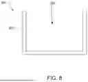
FIG. 8 is a top view of another transparent mullion 800. The transparent mullion 800 has a front wall 802 defining a front-facing surface 804 oriented toward the doors. 806 The transparent mullion 800 has two side walls 806, 808 coupled to the front wall 802. The side walls 806 and 808 are opposite one another. The walls 802, 806, and 808 define a body. In this implementation, the transparent mullion 800 has a U-shaped profile. The transparent mullion 800 supports the weight (i.e., is a load-bearing member extending from a bottom frame segment of the temperature controlled enclosure to a top frame segment of the temperature controlled enclosure.
In some implementations, a transparent mullion 800 includes a coating. The coating may or may not allow all light to pass through. In some cases, the coating can protect the transparent mullion 800 from the environment. In some environments, the conditions of the environment can affect the coating. Placing the coating on the transparent mullion 800 can increase the life of the transparent mullion 800. For example, some transparent mullion 800, when placed in a cold environment for a period of time, the cold environment may cause the transparent mullion 800 to turning yellow or cloud. The coating can prevent or decrease the degree of yellowing or clouding of the transparent mullion 800.
FIGS. 9-10 are perspective views of a third transparent mullion 900. The transparent mullion 900 has a transparent front-facing portion 902 defining one or more sealing surfaces 904 and a load-bearing portion 906. The transparent mullion 900 has an upper end 908 and a lower end 1002. The upper end 908 is opposite the lower end 1002. The upper end 908 is coupled to the top frame segment of the temperature controlled enclosure. The lower end 1002 is coupled to the bottom frame segment of the temperature controlled enclosure.
The load-bearing portion 906 has an upper load bearing portion 912 and a lower load bearing portion 1004. Referring to FIG. 9, the upper load bearing portion 912 attaches to the top frame segment of the temperature controlled enclosure. The upper load bearing portion 912 has a rectangular body 916 which inserts into the top frame segment of the temperature controlled enclosure and is coupled by fasteners passing through voids 918 extending through the rectangular body 916. A portion of the upper load bearing portion 912 is inserted into the transparent front facing portion 902 and held within the transparent front facing portion 902 by friction and/or an adhesive.
Referring to FIG. 10, the transparent mullion 900 is coupled to bottom frame segment of the temperature controlled enclosure at the lower end 1002 by the lower load bearing portion 1004. In this implementation, the lower load bearing portion 1004 is an L-shaped bracket. The upper load bearing portion 912 has a portion 1006 (i.e., a projection) which inserts into the transparent front facing portion 902 and held within the transparent front facing portion 902 by friction and/or an adhesive. The lower load bearing portion 1004 is coupled to the bottom frame segment 58.
In some implementations, the transparent front facing portion 902 has an internal groove 1008 on an inner surface 1010 in which one or both of the lower load bearing portion 1004 and the upper load bearing portion 912 slide into to engage to the transparent front facing portion 902.
In other implementations, the lower load bearing portion 1004 and the upper load bearing portion 912 are a single unitary piece that extends from the upper end 908 to the lower end 1002, i.e., a single load-bearing portion 906. In such implementations, the transparent front facing portion 902 can snap onto, or otherwise be fastened to, the load-bearing portion 906.
In some implementations, the doors or seals have magnets. The magnets can be one or more magnets arranged in an array so the magnets do not appreciably hinder viewing the products contained in the refrigerated enclosure 40. For example, an array of magnets can be in either the blades 524 and/or the mullion and door frame (e.g., the portion 704), or any other suitable portion of the refrigerated enclosure 40. The transparent mullion can have clear magnets or transparent magnetized elements to magnetically couple to the magnets on the doors.
Alternatively or in addition, the magnets can be an array of clear or translucent magnets. Using clear magnets can further enhance the customer's viewing experience and increase visual access to the refrigerated products. Using clear magnets can increase the quality of the scaling between the doors and the transparent mullions. For example, clear magnets can be optically transparent ferromagnetic materials such as nanogranular FeCo—(Al-fluoride) films.
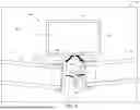
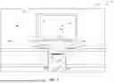
FIG. 11 is a view of a rear-facing portion of the refrigerated enclosure 40 of FIG. 1, from within the refrigerated enclosure 40. Referring to FIG. 11, the refrigerated enclosure 40 can include one or more lights to illuminate objects in the temperature-controlled enclosure 40. Refrigerated enclosure 40 includes the body 42 which has the top wall 44, the bottom wall 46, the left-side wall 48, the right-side wall 50, the doors 64, and a rear portion 1102 (the opposite side of the front portion 52) defining the temperature-controlled space. The rear portion 1102 is the inner surface of the front portion 52 within the refrigerated enclosure 40 proximal to the doors.
The refrigerated enclosure 40 can include one or more lights 1104a-d positioned on the rear portion 1102 of the refrigerated enclosure 40. The lights 1104a-d are spaced apart from the transparent mullions 82. No lights 1104a-d are placed on the transparent mullion 82 so the customers view is not blocked by the lights 104a-d. For instance, lights may not be necessary on the transparent mullions 82 because they may permit sufficient light into the display case from outside. The lights 1104a-d can be referred to as interior perimeter lighting. That is, the lights 1104a-d are coupled to and extend about some or all of the interior perimeter, or near the interior perimeter spaced outward from the doors 64.
The lights 1104a are positioned on the top frame segment 56. The lights 1104b are positioned on the bottom frame segment 58. The lights 1104c are positioned on the left-side frame segment 60. The lights 1104d are positioned on the right-side frame segment 62. The lights 1104a-d can extend of some or all of the length of each of the top frame segment 56, the bottom frame segment 58, the left-side frame segment 60, and the right-side frame segment 62 of the rear portion 1102. The lights 1104a-d can extend of some or all of the thickness of each of the top frame segment 56, the bottom frame segment 58, the left-side frame segment 60, and the right-side frame segment 62 of the rear portion 1102. Each of the lights 1104a-d can include one or more segments extending over some or all of the length of each of the top frame segment 56, the bottom frame segment 58, the left-side frame segment 60, and the right-side frame segment 62 of the rear portion 1102.
The lights 1104a-d are generally oriented away from the rear portion 1102 away from the doors 64 and the customer outside the refrigerated enclosure 40 and toward the interior of the refrigerated enclosure 40. The lights 1104a-d can be angled and any suitable angle between zero and one hundred and eighty degrees relative to the rear portion 1102 in one or both of a combination of the horizontal or vertical axis. The lights 1104a-d can be oriented to illuminate the refrigerated products contained within the refrigerated enclosure 40.
In some cases, the wattage of the elements or the size of individual elements of the lights 1104a-d can vary to increase or decrease the intensity of light at a desired location. In some implementations, the intensity of the illumination by the lights 1104b,d can increase based on the height of the individual elements of the lights 1104b,d based on the height from the bottom frame segment 58. In other words, the lights 1104b,d are brighter the higher the light placement. In other implementations, the intensity of the illumination by the lights 1104b,d can decrease based on the height of the individual elements of the lights 1104b,d based on the height from the bottom frame segment 58. In other words, the lights 1104b,d are brighter the lower the light placement in the refrigerated enclosure 40. In other implementations, the intensity of the illumination by the lights 1104b,d can increase and then decrease based on the height of the individual elements of the lights 1104b,d based on the height from the bottom frame segment 58. In other words, the lights 1104b,d increase in brightness as the height increases, then a point occurs where the brightness of the lights decreases as the height increases in the refrigerated enclosure 40.
In this implementation, the lights 1104a-d are light emitting diodes. However, in other implementations, any suitable light source may be used. In some implementations, the lights 1104a-d may increase the temperature of the top frame segment 56, the bottom frame segment 58, the left-side frame segment 60, and the right-side frame segment 62 of the rear portion 1102 along with heater wires coupled to or contained within the top frame segment 56, the bottom frame segment 58, the left-side frame segment 60, and the right-side frame segment 62 to reduce condensation and enhance the customer's viewing experience of the products within the refrigerated enclosure.
In various implementations described above, a temperature-controlled enclosure is illustrated in a door of a display case. In some implementations, a display door for a temperature-controlled enclosure is a walk-in temperature-controlled enclosure.
In various implementations described above, upper and lower gaskets are provided on the door-side of the interface between a door and a thermal frame. A gasket can, however, in some implementations, be on the other side of the interface. For example, in some implementations, upper and lower gaskets are secured to a thermal frame that resiliently engages a contact plate on the rear surface of the door.
In various implementations described above, adjoining doors each include insulating elements that engage one another. In other implementations, an inter-door insulating device is provided only on one of the doors. For example, an inter-door insulating device can be attached to one door and resiliently engage an adjacent door.
As used herein, “coupled” includes directly or indirectly connected. Two elements are coupled if they contact one another (e.g., where faces of a frame member and a contact plate are in contact with one another), but may also be coupled where they do not contact one another.
As used herein, the terms “perpendicular,” “substantially perpendicular,” or “approximately perpendicular” refer to an orientation of two elements (e.g., lines, axes, planes, surfaces, walls, or components) with respect to one and other that forms a ninety-degree (perpendicular) angle within acceptable engineering, machining, or measurement tolerances. For example, two surfaces can be considered orthogonal to each other if the angle between the surfaces is within an acceptable tolerance of ninety degrees (e.g., ±1-5 degrees).
As used herein, a “ridge” includes any element or portion thereof that projects from a surface of a component over at least a portion of the surface. A ridge may be in the form of, for example, a rail, elongated protrusion, rim, bar, or lip. A ridge can project in any direction, including up, down, left, right, sideways, or obliquely.
As used herein, an “air passage” includes any space that allows air to move through or within. In some cases, an air passage can be a through passage that permits air to continuously flow through the passage from one end to another. In other cases, an air passage (or portion thereof) is a blind passage that does not allow for continuous airflow. Air movement in a passage can be caused by pressure differentials, thermal gradients, or otherwise. “Air passage” does not imply that air actually moves within the air passage.
It should be noted that the orientation of various elements may differ according to other exemplary embodiments and that such variations are intended to be encompassed by the present disclosure.
While a number of examples have been described for illustration purposes, the foregoing description is not intended to limit the scope of the invention, which is defined by the scope of the appended claims. There are and will be other examples and modifications within the scope of the following claims. For example, the construction and arrangement of the refrigerated enclosure with a thermal door frame as shown in the various exemplary embodiments is illustrative only. Although only a few embodiments of the present inventions have been described in detail in this disclosure, those skilled in the art who review this disclosure will readily appreciate that many modifications are possible (e.g., variations in sizes, dimensions, structures, shapes and proportions of the various elements, values of parameters, mounting arrangements, use of materials, colors, orientations, etc.) without materially departing from the description and advantages of the subject matter disclosed herein. For example, elements shown as integrally formed may be constructed of multiple parts or elements, the position of elements may be reversed or otherwise varied, and the nature or number of discrete elements or positions may be altered or varied. Accordingly, all such modifications are intended to be included within the scope of the present invention as defined in the appended claims. Other substitutions, modifications, changes, and omissions may be made in the design, operating conditions, and arrangement of the various exemplary embodiments without departing from the scope of the present inventions.
Claims
What is claimed is:1. A mullion for a temperature-controlled enclosure, comprising:
a transparent front-facing portion defining one or more sealing surfaces; and
a load-bearing portion.
2. The mullion of claim 1, wherein
the mullion comprises a body having a rectangular tubular shape, and
at least a forward-facing wall of the body is transparent.
3. The mullion of claim 1, wherein the mullion comprises a body defines a U-shape and comprises:
a transparent-front-facing portion; and
a pair of opposing side walls.
4. The mullion of claim 1, wherein the mullion is configured to extend between an upper frame portion of the temperature-controlled enclosure and a lower frame portion of the temperature-controlled enclosure.
5. The mullion of claim 4, wherein the load-bearing portion is configured to bear a portion of a weight of the upper frame portion of the temperature-controlled enclosure.
6. The mullion of claim 1, wherein the mullion comprises:
a body, wherein at least a portion of the body is included in the load-bearing portion; and
a transparent front plate configured to snap into the body, the transparent front plate comprising at least one of the one or more sealing surfaces.
7. The mullion of claim 1, further comprising one or more connecting brackets configured to couple the mullion to a frame of the temperature-controlled enclosure.
8. The mullion of claim 1, further comprising a resilient seal configured to contact one or more surfaces of doors of the temperature-controlled enclosure.
9. The mullion of claim 1, further comprising one or more perimeter lights positioned about mullion and coupled to the temperature-controlled enclosure, the perimeter lights configured to illuminate objects in the temperature-controlled enclosure.
10. A temperature-controlled enclosure for displaying cold items, comprising:
a body comprising a front opening and defining an interior space of the temperature-controlled enclosure;
a frame assembly coupled in the front opening of the body, the frame assembly comprising an upper frame portion and a lower frame portion;
two or more doors coupled to the frame assembly, at least two of the doors comprising one or more transparent panes; and
one or more mullions coupled to the frame assembly and extending from the upper frame portion and the lower frame portion, wherein each of at least one of the mullions is between two adjoining ones of the two or more doors, the one or more mullion comprising a front-facing transparent portion.
11. The temperature-controlled enclosure of claim 10, wherein further comprising one or more brackets, each of at least one of the brackets coupled between the one or more mullions and the upper frame portion or the lower frame portion.
12. The temperature-controlled enclosure of claim 11, wherein at least one of the brackets comprises a projection that extends into the one or more mullions.
13. The temperature-controlled enclosure of claim 10, further comprising one or more lights coupled to the one or more mullions and configured to illuminate objects in the temperature-controlled enclosure.
14. The temperature-controlled enclosure of claim 10, wherein at least one of the mullions comprises a load bearing portion configured to bear a portion of a weight of the upper frame portion of the temperature-controlled enclosure.
15. The temperature-controlled enclosure of claim 10, further comprising one or more insulating devices coupled to at least one of the two or more doors and configured to contact the one or more mullions at least when at least one door is closed.
16. The temperature-controlled enclosure of claim 15, wherein at least one of the insulating devices comprises a blade.
17. The temperature-controlled enclosure of claim 10, further comprising insulating devices on at least one of the two adjoining doors coupled to a sealing surface of at least one of the mullions.
18. The temperature-controlled enclosure of claim 17, wherein the insulating devices comprises a resilient blade configured to engage the sealing surface.
19. The temperature-controlled enclosure of claim 18, wherein the resilient blade extends at an angle relative a rear surface of the doors.
20. The temperature-controlled enclosure of claim 17, wherein the insulating device comprises a resilient bulb.
21. The temperature-controlled enclosure of claim 10, further comprising one or more perimeter lights positioned about mullion and coupled to the temperature-controlled enclosure, the perimeter lights configured to illuminate objects in the temperature-controlled enclosure.
22. A system for maintaining temperature in a temperature-controlled enclosure, comprising:
a door comprising one or more transparent panes;
a mullion comprising a transparent front-facing portion; and
an insulating device that resides between the door and the mullion when the door is closed, wherein the insulating device comprises a transparent blade.
23. The system of claim 22, further comprising one or more perimeter lights positioned about mullion and coupled to the temperature-controlled enclosure, the perimeter lights configured to illuminate objects in the temperature-controlled enclosure.
Images & Drawings included:


Sources:
- United States Patent and Trademark Office - verify current appl. status at the USPTO↗
Recent applications in this class:
- » 20260047696 2026-02-19
REFRIGERATOR - » 20260007255 2026-01-08
A REFRIGERATION UNIT AND SYSTEM - » 20250375049 2025-12-11
REFRIGERATOR HAVING PANEL ASSEMBLY COVERING OPENING OF OUTER PLATE OF DOOR - » 20250344880 2025-11-13
REFRIGERATOR - » 20250040732 2025-02-06
REFRIGERATOR - » 20250040731 2025-02-06
REFRIGERATOR HAVING PANEL ASSEMBLY COVERING OPENING OF OUTER PLATE OF DOOR - » 20240122375 2024-04-18
Display case door with door frame electrical connection - » 20240081555 2024-03-14
AEROTHERMODYNAMIC SEPARATOR FOR REFRIGERATED DISPLAY CABINET - » 20240008661 2024-01-11
Refrigerator - » 20230329454 2023-10-19
Refrigerator having panel assembly covering opening of outer plate of door