MARINE PROPULSION DEVICE
US20260054813A1
2026-02-26
19/282,008
2025-07-28
Smart Summary: A marine propulsion device helps boats move through water. It has a motor that powers a drive shaft, which then turns a propeller shaft connected to a propeller. The motor is positioned so that its output shaft runs from front to back. There are two mechanisms that help transfer the motor's rotation to the drive and propeller shafts. The setup allows the propeller to be located at the back of the device, making it efficient for propulsion. 🚀 TL;DR
Abstract:
A marine propulsion device includes: a motor; a drive shaft; a first transmission mechanism that transmits rotation of an output shaft of the motor to the drive shaft; a propeller shaft; a second transmission mechanism that transmits rotation of the drive shaft to the propeller shaft; and a propeller. The motor is disposed so that an extension direction of the output shaft is a front-rear direction. The first transmission mechanism is disposed in front of the motor. The second transmission mechanism is disposed below the first transmission mechanism. The drive shaft extends in a vertical direction between the first transmission mechanism and the second transmission mechanism. The propeller shaft extends rearward from the second transmission mechanism. The propeller is provided in a rear part of the propeller shaft.
Assignee:
- SUZUKI MOTOR CORPORATION 546 🇯🇵 Hamamatsu-shi, Japan
Applicant:
Interested in similar patents?
Get notified when new applications in this technology area are published.
Classification:
B63H20/20 » CPC main
Outboard propulsion units, e.g. outboard motors or Z-drives; Arrangements thereof on vessels; Transmission between propulsion power unit and propulsion element with provision for reverse drive
B63H20/12 » CPC further
Outboard propulsion units, e.g. outboard motors or Z-drives; Arrangements thereof on vessels; Means enabling movement of the position of the propulsion element, e.g. for trim, tilt or steering; Control of trim or tilt Means enabling steering
Description
CROSS-REFERENCE TO RELATED APPLICATION(S)
This application is based on and claims priority under 35 USC 119 from Japanese Patent Application No. 2024-144580 filed on Aug. 26, 2024, the entire content of which is incorporated herein by reference.
TECHNICAL FIELD
The present invention relates to a marine propulsion device including a motor as a power source for rotating a propeller.
BACKGROUND ART
JP2005-162055A (Patent Literature 1) describes an outboard motor including a motor (electric motor) as a power source for rotating a propeller. In the outboard motor, the motor is disposed in an upper part of the outboard motor and the propeller is disposed in a lower part of the outboard motor. That is, when the outboard motor is mounted on a boat, the motor is positioned above the water surface and the propeller is positioned below the water surface.
In the outboard motor, the motor is disposed vertically so that an output shaft thereof extends in a vertical direction. The outboard motor is also provided with a drive shaft that extends in the vertical direction from the motor toward a propeller shaft, and a lower end of the output shaft of the motor and an upper end of the drive shaft are connected to each other via a drive gear and a driven gear. A lower end of the drive shaft is connected to the propeller shaft via a bevel gear, and the propeller is provided in the propeller shaft.
CITATION LIST
Patent Literature
- Patent Literature 1: JP2005-162055A
Generally, most motors have an axial dimension (direction in which an output shaft extends) greater than a radial dimension. Therefore, when the motor is disposed vertically so that an output shaft thereof extends in the vertical direction of the outboard motor, as in the outboard motor described in JP2005-162055A, a vertical dimension of a marine propulsion device tends to be large.
SUMMARY
The present invention is made considering, for example, the problem described above, and an object of the present invention is to provide a marine propulsion device in which a vertical dimension of the marine propulsion device is reduced.
To solve the above problem, the present invention provides a marine propulsion device including: a motor;
-
- a drive shaft;
- a first transmission mechanism configured to transmit rotation of an output shaft of the motor to the drive shaft;
- a propeller shaft;
- a second transmission mechanism configured to transmit rotation of the drive shaft to the propeller shaft; and
- a propeller, wherein
- the motor is disposed so that an extension direction of the output shaft is a front-rear direction,
- the first transmission mechanism is disposed in front of the motor,
- the second transmission mechanism is disposed below the first transmission mechanism,
- the drive shaft extends in a vertical direction between the first transmission mechanism and the second transmission mechanism,
- the propeller shaft extends rearward from the second transmission mechanism, and
- the propeller is provided in a rear part of the propeller shaft.
According to the present invention, a vertical dimension of a marine propulsion device can be reduced.
BRIEF DESCRIPTION OF DRAWINGS
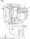
FIG. 1 is an overall view illustrating a marine propulsion device according to an example of the present invention as viewed from the left.
FIG. 2 is an explanatory diagram illustrating an upper part of the marine propulsion device in FIG. 1 as viewed from behind.
FIG. 3 is a cross-sectional view of the marine propulsion device cut along a line III-III in FIG. 2 as viewed from the left.
FIG. 4 is a perspective view illustrating the upper part of the marine propulsion device in FIG. 1.
FIG. 5 is an explanatory diagram illustrating a motor, a speed reducer housing, a drive shaft housing, a mount housing, a lower case, and an inverter separated from each other in the marine propulsion device according to the example of the present invention.
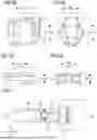
FIG. 6 is an explanatory diagram illustrating dimensions of the motor in the marine propulsion device according to the example of the present invention.
FIG. 7 is an explanatory diagram illustrating dimensions of the inverter in the marine propulsion device according to the example of the present invention.
FIG. 8 is an explanatory diagram illustrating a pilot shaft, an upper mount, a shift rod, and the like in the marine propulsion device according to the example of the present invention as viewed from above.
DESCRIPTION OF EMBODIMENTS
A marine propulsion device according to an embodiment of the present invention includes a motor, a drive shaft, a first transmission mechanism for transmitting rotation of an output shaft of the motor to the drive shaft, a propeller shaft, a second transmission mechanism for transmitting rotation of the drive shaft to the propeller shaft, and a propeller.
In the marine propulsion device of the embodiment, the motor is disposed so that an extension direction of an output shaft thereof is a front-rear direction. The first transmission mechanism is disposed in front of the motor. The second transmission mechanism is disposed below the first transmission mechanism. The drive shaft extends vertically between the first transmission mechanism and the second transmission mechanism. The propeller shaft extends rearward from the second transmission mechanism. The propeller is provided in a rear part of the propeller shaft.
In the marine propulsion device of the embodiment, when the motor is driven, the rotation of the output shaft is transmitted to the drive shaft by the first transmission mechanism, and the rotation of the drive shaft is transmitted to the propeller shaft by the second transmission mechanism. Accordingly, the propeller shaft rotates and the propeller rotates.
In the marine propulsion device of the embodiment, the motor is disposed horizontally so that an extension direction of the output shaft thereof is the front-rear direction. Generally, most motors have a radial dimension smaller than an axial dimension. Therefore, according to the marine propulsion device of the embodiment, the motor is disposed horizontally so that the extension direction of the output shaft thereof is the front-rear direction of the marine propulsion device, whereby a vertical dimension of the entire marine propulsion device can be made smaller than that of a marine propulsion device in which the motor is disposed vertically so that the extension direction of the output shaft thereof is the vertical direction of the marine propulsion device.
Example
A marine propulsion device according to an example of the present invention will be described with reference to drawings. In the description of the example, directions of up (Ud), down (Dd), front (Fd), back (Bd), left (Ld), and right (Rd) follow arrows drawn at the lower left in FIGS. 1 to 5 and 8. The directions refer to directions in the marine propulsion device.
FIG. 1 illustrates a marine propulsion device 1 according to the example of the present invention as viewed from the left. FIG. 2 illustrates an upper part of the marine propulsion device 1 as viewed from behind. FIG. 3 illustrates a cross section of the marine propulsion device 1 cut along a line III-III in FIG. 2 as viewed from the left. FIG. 4 illustrates the upper part of the marine propulsion device 1 as viewed from the upper left front. FIG. 5 illustrates a motor 3, a speed reducer housing 25, a drive shaft housing 26, a mount housing 28, a lower case 27, and an inverter 35 separated from each other.
In FIG. 1, the marine propulsion device 1 is a device for propelling a boat. The marine propulsion device 1 of the example is an outboard motor, and is mounted on the boat. The marine propulsion device 1 includes a marine propulsion device body 2, a pair of left and right clamp brackets 51 that mount the marine propulsion device body 2 on the boat, a pilot shaft 52 that pivots the marine propulsion device body 2 horizontally relative to the boat, a swivel bracket 53 that supports the pilot shaft 52 to be pivotable, a pair of left and right upper mounts 57 that connect an upper end of the pilot shaft 52 to the marine propulsion device body 2, and a pair of left and right lower mounts 60 that connect a lower end of the pilot shaft 52 to the marine propulsion device body 2. The upper mount 57 is a specific example of a “mount”.
As illustrated in FIG. 3, the marine propulsion device body 2 includes the motor 3 as a power source for rotating a propeller 20, a drive shaft 8 that transmits power of the motor 3 to the propeller 20, a speed reducer 9 that reduces rotation of an output shaft 4 of the motor 3 and transmits the rotation to the drive shaft 8, a propeller shaft 13, a rotation transmission mechanism 14 that transmits rotation of the drive shaft 8 to the propeller shaft 13, and the propeller 20 that converts the power of the motor 3 into thrust for the boat. The speed reducer 9 is a specific example of a “first transmission mechanism”, and the rotation transmission mechanism 14 is a specific example of a “second transmission mechanism”.
The motor 3 and the speed reducer 9 are disposed in an upper part of the marine propulsion device body 2. When the marine propulsion device 1 is mounted on the boat, the motor 3 and the speed reducer 9 are positioned above the water surface. Meanwhile, the rotation transmission mechanism 14, the propeller shaft 13, and the propeller 20 are disposed in a lower part of the marine propulsion device body 2. When the marine propulsion device 1 is mounted on the boat, the rotation transmission mechanism 14, the propeller shaft 13, and the propeller 20 are positioned below the water surface.
As illustrated in FIG. 3, the motor 3 includes the output shaft 4 that serves as a power output shaft, a rotor 5 provided on an outer periphery of the output shaft 4, a stator 6 provided on an outer periphery of the rotor 5, and a motor case 7 having a substantially cylindrical shape. The output shaft 4 excluding a tip, the rotor 5, and the stator 6 are accommodated in the motor case 7.
Here, FIG. 6A illustrates the motor 3. FIG. 6B illustrates the motor 3 in FIG. 6A as viewed from the right in FIG. 6A. As illustrated in FIGS. 6A and 6B, when comparing each of a dimension L1 in a direction D1 in which the output shaft 4 extends, a dimension L2 in a direction D2 perpendicular to the direction D1, and a dimension L3 in a direction D3 perpendicular to the directions D1 and D2 in the motor 3, the dimension L1 is larger than both the dimensions L2 and L3, and the dimension L3 is larger than the dimension L2.
As illustrated in FIG. 3, the motor 3 is disposed so that an extension direction of the output shaft 4 is a front-rear direction. That is, as can be seen from FIGS. 1, 3, 6A, and 6B, the motor 3 is positioned so that the direction D1 is the front-rear direction of the marine propulsion device 1, the direction D2 is a left-right direction of the marine propulsion device 1, and the direction D3 is a vertical direction of the marine propulsion device 1.
As illustrated in FIG. 3, the speed reducer 9 is disposed in front of the motor 3. The speed reducer 9 includes a motor drive gear 10, a reduction gear 11, and a connecting shaft 12. Both the motor drive gear 10 and the reduction gear 11 are bevel gears. A rotation axis of the motor drive gear 10 extends in the front-rear direction. A rear part of the motor drive gear is coupled to a front part of the output shaft 4 of the motor 3, and the motor drive gear 10 rotates integrally with the output shaft 4. A rotation axis of the reduction gear 11 extends in the vertical direction. The reduction gear 11 is disposed in front of the motor drive gear 10 and meshes with the motor drive gear 10. A gear ratio between the motor drive gear 10 and the reduction gear 11 (the number of teeth of the reduction gear 11/the number of teeth of the motor drive gear 10) is greater than 1. The connecting shaft 12 extends in the vertical direction. The reduction gear 11 is coupled to an upper end of the connecting shaft 12, and the connecting shaft 12 rotates integrally with the reduction gear 11.
The drive shaft 8 extends in the vertical direction. The drive shaft 8 is disposed between the speed reducer 9 and the rotation transmission mechanism 14. An upper end of the drive shaft 8 is connected to a lower end of the connecting shaft 12 of the speed reducer 9, and the drive shaft 8 rotates integrally with the connecting shaft 12.
The rotation transmission mechanism 14 is disposed below the speed reducer 9. The rotation transmission mechanism 14 includes a transmission gear 15, a forward gear 16, a reverse gear 17, a dog clutch 18, and a shift plunger 19. The transmission gear 15, the forward gear 16, and the reverse gear 17 are all bevel gears. A rotation axis of the transmission gear 15 extends in the vertical direction. The transmission gear 15 is coupled to a lower end of the drive shaft 8 and rotates integrally with the drive shaft 8. Rotation axes of the forward gear 16 and the reverse gear 17 extend in the front-rear direction. The forward gear 16 is disposed in front of the transmission gear 15, and the reverse gear 17 is disposed behind the transmission gear 15. The forward gear 16 and the reverse gear 17 each mesh with the transmission gear 15, and upon receiving rotation of the transmission gear 15, the forward gear 16 and the reverse gear 17 rotate in opposite directions to each other. A through hole is formed in each of a center of the forward gear 16 and a center of the reverse gear 17, and a front part of the propeller shaft 13 is inserted into the through holes. The forward gear 16 and the reverse gear 17 are not fixed to the propeller shaft 13 and are rotatable relative to the propeller shaft 13. The dog clutch 18 is disposed between the forward gear 16 and the reverse gear 17. The dog clutch 18 is attached to the front part of the propeller shaft 13 to not be rotatable relative to the propeller shaft 13 but to be movable in the front-rear direction relative to the propeller shaft 13. The shift plunger 19 is attached inside a front end of the propeller shaft 13 to be movable in the front-rear direction relative to the propeller shaft 13. A rear end of the shift plunger 19 is connected to the dog clutch 18 and a front end of the shift plunger 19 is positioned near a lower end of a shift rod 33, so that pivoting of the shift rod 33 is transmitted to the shift plunger 19 via a cam mechanism. When the shift rod 33 pivots due to driving of a shift actuator 32, the pivoting of the shift rod 33 is transmitted to the shift plunger 19 via the cam mechanism, causing the shift plunger 19 to move forward or rearward, and in response, the dog clutch 18 moves forward or rearward. When the dog clutch 18 moves forward, the dog clutch 18 and the forward gear 16 engage with each other, thereby transmitting rotation of the forward gear 16 to the propeller shaft 13. Meanwhile, when the dog clutch 18 moves rearward, the dog clutch 18 and the reverse gear 17 engage with each other, thereby transmitting rotation of the reverse gear 17 to the propeller shaft 13. The dog clutch 18 and the shift plunger 19 are specific examples of a “rotation direction switching mechanism”.
The propeller shaft 13 extends in the front-rear direction. The front part of the propeller shaft 13 extends into the rotation transmission mechanism 14, and a rear part of the propeller shaft 13 extends rearward from the rotation transmission mechanism 14. The propeller 20 is fixed to the rear part of the propeller shaft 13 and rotates integrally with the propeller shaft 13.
When the motor 3 is driven, the rotation of the output shaft 4 of the motor 3 is transmitted to the forward gear 16 and reverse gear 17 via the motor drive gear 10, the reduction gear 11, the connecting shaft 12, the drive shaft 8, and the transmission gear 15 in this order. When the dog clutch 18 is moved forward, the rotation of the forward gear 16 is transmitted to the propeller shaft 13 so that the propeller shaft 13 and the propeller 20 are rotated forward. Forward rotation of the propeller 20 generates thrust that moves the boat forward. Meanwhile, when the dog clutch 18 is moved rearward, the rotation of the reverse gear 17 is transmitted to the propeller shaft 13 so that the propeller shaft 13 and the propeller are rotated reversely. Reverse rotation of the propeller 20 generates thrust that moves the boat rearward.
The marine propulsion device body 2 also includes the speed reducer housing 25 that covers the speed reducer 9, the drive shaft housing 26 that covers the upper part of the drive shaft 8, the lower case 27 that covers the lower part of the drive shaft 8, the rotation transmission mechanism 14, and the front part of the propeller shaft 13, and the mount housing 28 that covers the upper mount 57. The speed reducer housing 25 is a specific example of a “transmission mechanism housing”.
As can be seen from FIGS. 1, 3, and 5, the drive shaft housing 26 is disposed below the speed reducer housing 25 and is attached to the speed reducer housing 25 using a fastening member such as a bolt. The lower case 27 is disposed below the drive shaft housing 26 and is attached to the drive shaft housing 26 using a fastening member such as a bolt. The mount housing 28 is disposed above the speed reducer housing 25 and is attached to the speed reducer housing 25 using a fastening member such as a bolt.
The motor 3 is positioned behind the speed reducer housing 25 and the drive shaft housing 26. Specifically, an upper part of the motor 3 is positioned behind the speed reducer housing 25 and a lower part of the motor 3 is positioned behind the drive shaft housing 26. As illustrated in FIG. 5, attachment portions 41 and 42 are respectively provided in a rear part of the speed reducer housing 25 and in an upper front part of the motor case 7 of the motor 3. Attachment portions 43 and 44 are respectively provided in a rear part of the drive shaft housing 26 and in a lower front part of the motor case 7. As illustrated in FIG. 1, the motor 3 is attached to the speed reducer housing 25 by coupling the attachment portion 42 of the motor 3 to the attachment portion 41 of the speed reducer housing 25 using a fastening member such as a bolt. The motor 3 is attached to the drive shaft housing 26 by coupling the attachment portion 44 of the motor 3 to the attachment portion 43 of the drive shaft housing 26 using a fastening member such as a bolt.
As illustrated in FIG. 3, the marine propulsion device body 2 includes a shift device 31 that controls switching of a rotation direction of the propeller 20. The shift device 31 includes the shift actuator 32 and the shift rod 33. The shift actuator 32 is an actuator that controls movement of the dog clutch 18, and is provided above and in front of the mount housing 28. The shift actuator 32 is positioned above a rear part of the swivel bracket 53, and when the marine propulsion device 1 is viewed from above, the shift actuator 32 is in a position that overlaps with the rear part of the swivel bracket 53. The shift actuator 32 is positioned above the pilot shaft 52. The shift actuator 32 is, for example, a small motor. The shift rod 33 is a rod that transmits power from the shift actuator 32 to the shift plunger 19. The shift rod 33 extends in the vertical direction from the shift actuator 32 toward the front end of the shift plunger 19. An upper end of the shift rod 33 is connected to the shift actuator 32. A lower end of the shift rod 33 is positioned near the front end of the shift plunger 19.
When the power source for rotating the propeller is a motor, possible methods for switching the rotation direction of the propeller include, for example, controlling an inverter to switch the rotation direction of a rotor of the motor, or keeping the rotation direction of a rotor of the motor constant and switching the rotation direction of a shaft provided midway along a path that transmits rotation of the rotor of the motor to the propeller, using, for example, a dog clutch. The latter method is applied to the marine propulsion device 1 of the example. The shift actuator 32 is electrically connected to, for example, a selector switch provided on a bar handle attached to the marine propulsion device 1 or an angle sensor that detects a tilt angle of a lever of a remote control device provided on the boat. The shift actuator 32 pivots the shift rod 33 in response to an operation of the selector switch on the handlebar or the lever of the remote control device. Rotational motion of the shift rod 33 is converted into linear motion in the front-rear direction of the shift plunger 19 by a cam mechanism provided between the lower end of the shift rod 33 and the front end of the shift plunger 19. As described above, movement of the shift plunger 19 causes the dog clutch 18 to move, and when the dog clutch 18 and the forward gear 16 engage with each other, the propeller 20 is rotated forward, generating thrust that moves the boat forward, and when the dog clutch 18 and the reverse gear 17 engage with each other, the propeller 20 is rotates reversely, generating thrust that moves the boat rearward. Accordingly, a boat operator can switch between forward and reverse driving of the boat by operating a selector switch on a bar handle or a lever on a remote control device.
The marine propulsion device body 2 includes the inverter 35 that controls the driving of the motor 3. As illustrated in FIG. 1, the inverter 35 includes an inverter body 36 provided with electric and electronic circuits that control the driving of the motor 3, and an inverter case 37 that accommodates the inverter body 36.
Here, FIG. 7A illustrates the inverter 35. FIG. 7B illustrates the inverter 35 in FIG. 7A as viewed from the right in FIG. 7A. As illustrated in FIGS. 7A and 7B, an outer shape of the inverter 35 is generally rectangular parallelepiped. When comparing a dimension M1 in a direction E1, a dimension M2 in a direction E2 perpendicular to the direction E1, and a dimension M3 in a direction E3 perpendicular to the directions E1 and E2 in the inverter 35, the dimension M1 is larger than both the dimensions M2 and M3, and the dimension M2 is larger than the dimension M3.
As illustrated in FIG. 1, the inverter 35 is disposed above the motor 3. As can be seen from FIGS. 1, 7A and 7B, the inverter 35 is positioned so that direction E1 is the front-rear direction of the marine propulsion device 1, the direction E2 is the left-right direction of the marine propulsion device 1, and the direction E3 is the vertical direction of the marine propulsion device 1. In other words, the inverter 35 is disposed so that the direction E1 coincides with the extension direction of the output shaft 4 of the motor 3. The inverter 35 is positioned below an upper end of the mount housing 28. In the example, the inverter 35 is positioned below an upper surface 28A of the mount housing 28.
The inverter 35 is attached to the motor 3. As illustrated in FIG. 5, attachment portions 45 and 46 are respectively provided in an upper left front part of the motor case 7 of the motor 3 and in a lower left front part of the inverter case 37 of the inverter 35. Similar attachment portions are also provided in an upper right front part of the motor case 7 and in a lower right front part of the inverter case 37. Attachment portions 47 and 48 are respectively provided in an upper left rear part of the motor case 7 and in a lower left rear part of the inverter case 37. Similar attachment portions are also respectively provided in an upper right rear part of the motor case 7 and in a lower right rear part of the inverter case 37. The inverter is attached to the motor 3 by coupling the left and right attachment portions 46 of the inverter 35 to the left and right attachment portions 45 of the motor 3 and coupling the left and right attachment portions 48 of the inverter 35 to the left and right attachment portions 47 of the motor 3 using fastening members such as bolts.
As illustrated in FIG. 4, the pair of left and right clamp brackets 51 and the swivel bracket 53 are disposed in front of the upper part of the marine propulsion device body 2. The swivel bracket 53 is disposed between the pair of clamp brackets 51. The swivel bracket 53 is coupled to each clamp bracket 51 via a tilt shaft 54, and the swivel bracket 53 can pivot (tilt up, tilt down) in the vertical direction relative to each clamp bracket 51 with the tilt shaft 54 as a pivot axis. A tilt cylinder 55 is provided between the pair of clamp brackets 51.
As illustrated in FIG. 3, the pilot shaft 52 extends in the vertical direction and is supported by the swivel bracket 53 to be pivotable. An upper mount fixing member 56 is coupled to the upper end of the pilot shaft 52, and front parts of the pair of left and right upper mounts 57 are fixed to the upper mount fixing member 56. Rear parts of the pair of upper mounts 57 each enter into the mount housing 28 and are attached to the mount housing 28 in the mount housing 28. A steering bracket 58 is provided in a front part of the upper mount fixing member 56. A lower mount fixing member 59 is coupled to the lower end of the pilot shaft 52, and front parts of the pair of left and right lower mounts 60 are fixed to the lower mount fixing member 59. As illustrated in FIG. 4, rear parts of the pair of lower mounts 60 are attached to the drive shaft housing 26.
FIG. 8 illustrates the pilot shaft 52, the upper mount fixing member 56, the upper mount 57, the steering bracket 58, and the shift rod 33 as viewed from above. As can be seen in FIGS. 1, 3, 4, and 8, an upper part of the shift rod 33 passes between the pair of upper mounts 57. As can be seen from FIGS. 1 and 3, the upper part of the shift rod 33 passes between the swivel bracket 53 and the speed reducer housing 25. A vertical middle part of the shift rod 33 passes between the pair of lower mounts 60. As illustrated in FIG. 3, a lower part of the shift rod 33 passes inside of the lower case 27.
As described above, in the marine propulsion device 1 according to the example of the present invention, the motor 3 is disposed horizontally so that the extension direction of the output shaft 4 is the front-rear direction. In FIGS. 6A and 6B, when the motor 3 is disposed horizontally so that the extension direction of the output shaft 4 is the front-rear direction, a dimension of the motor 3 in the vertical direction of the marine propulsion device 1 is the dimension L3 in the direction D3 of the motor 3. Meanwhile, when the motor 3 is disposed vertically so that the extension direction of the output shaft 4 is the vertical direction, the dimension of the motor 3 in the vertical direction of the marine propulsion device 1 is the dimension L1 in the direction D1 of the motor 3. As illustrated in FIGS. 6A and 6B, the dimension L3 is less than the dimension L1. Therefore, by disposing the motor 3 horizontally so that the extension direction of the output shaft 4 is the front-rear direction, the dimension in the vertical direction of the marine propulsion device 1 can be reduced compared to when the motor 3 is disposed vertically so that the extension direction of the output shaft 4 is the vertical direction.
The marine propulsion device 1 of the example includes the speed reducer housing that covers the speed reducer 9, and the drive shaft housing 26 that is disposed below the speed reducer housing 25 and covers the upper part of the drive shaft 8, where the upper part of the motor 3 is positioned behind the speed reducer housing 25, and the lower part of the motor 3 is positioned behind the drive shaft housing 26. That is, in the example, the motor 3 is disposed behind the speed reducer 9 and the upper part of the drive shaft 8. By such configuration, a vertical dimension of the marine propulsion device 1 can be made smaller than when the motor 3 is disposed vertically and above the speed reducer 9 and the drive shaft 8.
In the marine propulsion device 1 of the example, the inverter 35 is disposed above the motor 3 and mounted on the motor 3, and the inverter 35 is positioned below the upper end of the mount housing 28. By such configuration, a position of the inverter 35 is lowered. It is possible to prevent a portion of the inverter 35 from protruding upward. Therefore, the vertical dimension of the marine propulsion device 1 can be reduced. As can be seen from FIGS. 1, 7A, and 7B, the inverter 35 is disposed so that the direction E3 is the vertical direction of the marine propulsion device 1. As illustrated in FIGS. 7A and 7B, in the inverter 35, the dimension M3 in the direction E3 is smaller than both the dimension M1 in the direction E1 and the dimension M2 in the direction E2. Therefore, by disposing the inverter so that the direction E3 is the vertical direction of the marine propulsion device 1, the dimension of the inverter 35 in the vertical direction of the marine propulsion device 1 can be made smaller than when the inverter 35 is positioned so that the direction E1 is the vertical direction of the marine propulsion device 1, or when the inverter 35 is positioned so that the direction E2 is the vertical direction of the marine propulsion device 1. By disposing the inverter 35 above the motor 3 to be oriented as such, an amount by which the inverter 35 protrudes upward from the motor 3 can be reduced. As a result, the vertical dimension of the marine propulsion device 1 can be reduced.
In the marine propulsion device 1 of the example, the shift rod 33 extends from the shift actuator 32 passing between the pair of upper mounts 57 and between the pair of lower mounts 60 toward the front end of the shift plunger 19. By such configuration, each upper mount 57 and each lower mount 60 can function as a partition that prevents external objects from coming into contact with the shift rod 33, and each upper mount 57 and each lower mount 60 can protect the shift rod 33.
In the marine propulsion device 1 of the example, the shift rod 33 extends from the shift actuator 32 passing between the swivel bracket 53 and the speed reducer housing 25 toward the front end of the shift plunger 19. In some marine propulsion devices of the related arts, the shift rod passes inside a cylindrical pilot shaft. According to the marine propulsion device 1 of the example, the shift rod 33 can be more easily assembled to the marine propulsion device 1 than in the marine propulsion devices of the related arts. By disposing the shift rod 33 outside the pilot shaft 52, a degree of freedom in setting a distance between the shift rod 33 and the drive shaft 8 increases. Therefore, it is possible to easily set the distance between the shift rod 33 and the drive shaft 8 to suit, for example, the size and the arrangement of each gear in the rotation transmission mechanism 14.
In the marine propulsion device 1 of the above-described example, a battery serving as a power source for the motor 3 may be provided above the inverter 35. According to the battery-equipped marine propulsion device in which a battery is provided above the inverter of the marine propulsion device 1 of the above-described example, a vertical dimension of the battery-equipped marine propulsion device can be made smaller than that of other battery-equipped marine propulsion devices in which a battery is provided above an inverter of a marine propulsion device in which the inverter is disposed above a vertically disposed motor.
While the marine propulsion device 1 in the above-described example is an outboard motor, the present invention can also be applied to other types of marine propulsion devices other than outboard motors, such as inboard-outboard motors.
The present invention can be modified as appropriate without departing from the spirit or the concept of the invention as can be read from the claims and the entire specification, and marine propulsion devices incorporating such modifications are also included in the technical concept of the present invention.
Claims
1. A marine propulsion device comprising:
a motor;
a drive shaft;
a first transmission mechanism configured to transmit rotation of an output shaft of the motor to the drive shaft;
a propeller shaft;
a second transmission mechanism configured to transmit rotation of the drive shaft to the propeller shaft; and
a propeller, wherein
the motor is disposed so that an extension direction of the output shaft is a front-rear direction,
the first transmission mechanism is disposed in front of the motor,
the second transmission mechanism is disposed below the first transmission mechanism,
the drive shaft extends in a vertical direction between the first transmission mechanism and the second transmission mechanism,
the propeller shaft extends rearward from the second transmission mechanism, and
the propeller is provided in a rear part of the propeller shaft.
2. The marine propulsion device according to claim 1, further comprising:
a transmission mechanism housing configured to cover the first transmission mechanism; and
a drive shaft housing being disposed below the transmission mechanism housing and configured to cover an upper part of the drive shaft, wherein
an upper part of the motor is positioned behind the transmission mechanism housing, and a lower part of the motor is positioned behind the drive shaft housing.
3. The marine propulsion device according to claim 1, further comprising:
an inverter configured to control driving of the motor, wherein
the inverter is disposed above the motor and mounted on the motor.
4. The marine propulsion device according to claim 2, further comprising:
a marine propulsion device body including: the motor; the drive shaft; the first transmission mechanism; the propeller shaft; the second transmission mechanism; the propeller; the transmission mechanism housing; the drive shaft housing; a mount housing; and
an inverter;
a swivel bracket provided in front of the marine propulsion device body and configured to support a pilot shaft to be pivotable; and
a mount configured to connect the marine propulsion device body to an upper end of the pilot shaft, wherein
the mount housing is disposed above the transmission mechanism housing and attached to the transmission mechanism housing,
a rear part of the mount is attached to the mount housing, and
the inverter is a device configured to control driving of the motor, is disposed above the motor, and is positioned below an upper end of the mount housing.
5. The marine propulsion device according to claim 2, further comprising:
a marine propulsion device body including: the motor; the drive shaft; the first transmission mechanism; the propeller shaft; the second transmission mechanism; the propeller; the transmission mechanism housing; the drive shaft housing; a mount housing; a shift actuator; and a shift rod;
a swivel bracket provided in front of the marine propulsion device body and configured to support a pilot shaft to be pivotable; and
a pair of left and right mounts configured to connect the marine propulsion device body to an upper end of the pilot shaft, wherein
the mount housing is disposed above the transmission mechanism housing and attached to the transmission mechanism housing,
a rear part of each of the mounts is attached to the mount housing,
the second transmission mechanism is provided with a rotation direction switching mechanism that switches a rotation direction of the propeller shaft,
the shift actuator is an actuator that controls the rotation direction switching mechanism and is provided above or in front of the mount housing, and
the shift rod is a rod configured to transmit power from the shift actuator to the rotation direction switching mechanism, and extends from the shift actuator passing between the pair of mounts toward the rotation direction switching mechanism.
6. The marine propulsion device according to claim 2, further comprising:
a marine propulsion device body including: the motor; the drive shaft; the first transmission mechanism; the propeller shaft; the second transmission mechanism; the propeller; the transmission mechanism housing; the drive shaft housing; a mount housing; a shift actuator; and a shift rod;
a swivel bracket provided in front of the marine propulsion device body and configured to support a pilot shaft to be pivotable; and
a mount configured to connect the marine propulsion device body to an upper end of the pilot shaft, wherein
the mount housing is disposed above the transmission mechanism housing and attached to the transmission mechanism housing,
a rear part of the mount is attached to the mount housing,
the second transmission mechanism is provided with a rotation direction switching mechanism that switches a rotation direction of the propeller shaft,
the shift actuator is an actuator that controls the rotation direction switching mechanism and is provided above or in front of the mount housing, and
the shift rod is a rod configured to transmit power from the shift actuator to the rotation direction switching mechanism, and extends from the shift actuator passing between the swivel bracket and the transmission mechanism housing toward the rotation direction switching mechanism.
Images & Drawings included:


Sources:
- United States Patent and Trademark Office - verify current appl. status at the USPTO↗
Similar patent applications:
- » 20230382506
CHARGING CONTROL METHOD AND SYSTEM FOR MARINE PROPULSION DEVICE, AND MARINE PROPULSION DEVICE - » 20240116615
Marine propulsion device and method of controlling marine propulsion device - » 20200198747
Marine propulsion device controller for starting/stopping engine, marine propulsion system including the same, and engine starter of marine propulsion device - » 20220266969
Marine propulsion device and methods of making marine propulsion device having impact protection - » 14794971
Outboard marine propulsion devices and methods of making outboard marine propulsion devices having exhaust runner cooling passages - » 14543453
Outboard marine propulsion devices and exhaust systems for outboard marine propulsion devices - » 14570400
Marine propulsion devices and fuel injection systems for marine propulsion devices - » 20230306799
MARINE PROPULSION DEVICE INFORMATION TRANSMITTING AND RECEIVING SYSTEM AND MARINE PROPULSION DEVICE INFORMATION TRANSMITTING AND RECEIVING METHOD - » 20230127117
MARINE PROPULSION DEVICES HAVING ELECTRIC MOTORS AND METHODS FOR MAKING MARINE PROPULSION DEVICES HAVING ELECTRIC MOTORS - » 20210284311
Drive source switching system for marine propulsion device including multiple drive sources, and method of switching drive sources of marine propulsion device
Recent applications in this class:
- » 20250313324 2025-10-09
MARINE PROPULSION DEVICE - » 20240425164 2024-12-26
OUTBOARD MOTOR - » 20240109633 2024-04-04
DIVIDED GEAR WHEEL FOR A POWER TRANSMISSION SYSTEM USED IN A MARINE ENGINE - » 20230382509 2023-11-30
Outboard motor transmission with coaxial input and output shafts - » 20220348302 2022-11-03
Transmission element and gearbox of a power transmission system - » 20210188413 2021-06-24
Outboard motor - » 20210188412 2021-06-24
Divided gear wheel for a power transmission system used in a marine engine - » 20210171174 2021-06-10
Device for propelling a navigational seacraft, and navigational seacraft provided with such a device - » 20210129965 2021-05-06
Power transmission device and method for an outboard motor - » 20210001969 2021-01-07
Outboard motor
Recent applications for this Assignee:
- » 20260055721 2026-02-26
ELECTRIC PROPULSION MACHINE - » 20260054818 2026-02-26
MARINE PROPULSION DEVICE - » 20260054817 2026-02-26
MARINE PROPULSION DEVICE - » 20260054816 2026-02-26
OUTBOARD MOTOR - » 20260054815 2026-02-26
ELECTRIC PROPULSION DEVICE - » 20260054814 2026-02-26
ELECTRIC PROPULSION DEVICE - » 20260054812 2026-02-26
OUTBOARD MOTOR - » 20260054811 2026-02-26
OUTBOARD MOTOR - » 20260043372 2026-02-12
OUTBOARD-MOTOR CYLINDER BLOCK AND MANUFACTURING METHOD THEREFOR - » 20260028111 2026-01-29
SHIP PROPULSION MACHINE