HYBRID DRIVELINE CONTROL
US20260054820A1
2026-02-26
19/301,168
2025-08-15
Smart Summary: A computer system helps control the speed of a marine vessel that uses both electric and combustion engines. It calculates a target speed for the electric engine based on the desired speed and a set limit. Then, it figures out a target speed for the combustion engine using the same desired speed and limit. As the difference between the two target speeds gets smaller, it adjusts to stay within the speed limit. This system ensures the vessel operates efficiently by balancing power from both types of engines. 🚀 TL;DR
Abstract:
A computer system has processing circuitry to obtain a wanted speed of a marine vessel comprising a hybrid driveline; determine a first target speed for an electric propulsion source connected to the hybrid driveline based on the wanted speed and a speed threshold; determine a second target speed for a combustion propulsion source connected to the hybrid driveline based on the wanted speed and the speed threshold. A difference between the first target speed and the second target speed decreases with a difference between said target speeds and the speed threshold.
Assignee:
- Volvo Penta Corporation 86 🇸🇪 Göteborg, Sweden
Applicant:
Interested in similar patents?
Get notified when new applications in this technology area are published.
Classification:
B63H21/21 » CPC main
Use of propulsion power plant or units on vessels Control means for engine or transmission, specially adapted for use on marine vessels
B63H21/20 » CPC further
Use of propulsion power plant or units on vessels the vessels being powered by combinations of different types of propulsion units
B63H2021/202 » CPC further
Use of propulsion power plant or units on vessels the vessels being powered by combinations of different types of propulsion units of hybrid electric type
B63H2021/216 » CPC further
Use of propulsion power plant or units on vessels; Control means for engine or transmission, specially adapted for use on marine vessels using electric control means
Description
TECHNICAL FIELD
The disclosure relates generally to control of a driveline. In particular aspects, the disclosure relates to hybrid driveline control. The disclosure can be applied to marine vessels, such as leisure boats, ships, cruise ships, fishing vessels, yachts, ferries, among other vehicle types. Although the disclosure may be described with respect to a particular marine vessel, the disclosure is not restricted to any particular marine vessel.
BACKGROUND
In marine vessels utilizing both a combustion propulsion source and an electrical propulsion source, i.e. hybrid marine vessels, efficiency has been shown to be of great importance. Depending on the speed of the marine vessel, the respective utilization of the electric propulsion source and the combustion propulsion source may impact the overall energy optimization of the marine vessel, the emissions of the marine vessel and/or the noise generated by the propulsion of the marine vessel. It has been realized that there is a need for improvements with regards to the utilization of the combustion propulsion source and the electric propulsion source particular in situations where acceleration is required and/or to allow for smoother transitions between utilization of the electric propulsion source and the combustion propulsion source.
SUMMARY
According to a first aspect of the disclosure, a computer system is provided. The computer system comprises processing circuitry configured to obtain a wanted speed of a marine vessel comprising a hybrid driveline, determine a first target speed for an electric propulsion source connected to the hybrid driveline based on the wanted speed and a speed threshold, determine a second target speed for a combustion propulsion source connected to the hybrid driveline based on the wanted speed and the speed threshold. A difference between the first target speed and the second target speed decreases with a difference between said target speeds and the speed threshold. The processing circuitry is configured to control the electric propulsion source to the first target speed and the combustion propulsion source to the second target speed. The first aspect of the disclosure may seek to achieve a more energy optimizable marine vessel. A technical benefit may include that either the electric or combustion propulsion source may depending on the circumstances be utilized in order to smoothen transitions during switching between the propulsion sources or reaching a wanted speed in a more favorable manner in terms of generated noise, emissions, fuel consumption, re-charging capability etc.
Optionally in some examples, including in at least one preferred example, the processing circuitry may be further configured to responsive to the wanted speed being at the speed threshold determine the first and second target speed to be at the wanted speed. A technical benefit may include that the speed threshold utilized to allow for both the combustion propulsion source and the electric propulsion source to operate at the same speed when beneficial.
Optionally in some examples, including in at least one preferred example, the speed threshold may be determined based on a power threshold. The power threshold may be associated with used power of the hybrid driveline. A technical benefit may include that the speed threshold may be selected to allow for a more efficient utilization of the electric and combustion propulsion source in a specific operating region as the energy efficiency will vary depending on the used power and/or allow for control of the utilization of the electric propulsion source and the combustion propulsion source based on the current operation of the marine vessel.
Optionally in some examples, including in at least one preferred example, the speed threshold may be determined based on a planing speed of the marine vessel. A technical benefit may include that a large amount of power is usually required in order to cause the marine vessel to transition into a planing state, by selecting the speed threshold at or close to the planing speed, the transition into the planing state may be faster and smoother.
Optionally in some examples, including in at least one preferred example, the processing circuitry may be further configured to responsive to the wanted speed being below the speed threshold, determine the first target speed to be at the wanted speed, and determine the second target speed to be lower than the wanted speed. A technical benefit may include that electrical propulsion source may be more relied on to reach the wanted speed. This commonly allows for faster acceleration, due to an electric propulsion source usually being capable of increasing its speed faster than a combustion propulsion source.
Optionally in some examples, including in at least one preferred example, the processing circuitry may be further configured to responsive to the wanted speed being above the speed threshold determine the first target speed to be lower than the wanted speed, and determine the second target speed to be at the wanted speed. A technical benefit may include that the combustion propulsion source may be more relied upon to reach the wanted speed at higher speeds where combustion propulsion sources commonly are more energy efficient than electric propulsion sources.
Optionally in some examples, including in at least one preferred example, the processing circuitry may be further configured to responsive to the wanted speed being below the speed threshold determine the first target speed to be lower than the wanted speed, and determine the second target speed to be at the wanted speed. A technical benefit may include that an optimized operation may be achieved also in cases where the power source powering the electric propulsion source is running low.
Optionally in some examples, including in at least one preferred example, the speed threshold may be a predetermined threshold based on a planing speed of the marine vessel, and wherein the processing circuitry is further configured to in response to the wanted speed being below the speed threshold determine the first target speed to be at the wanted speed, and determine the second target speed to be lower than the speed threshold, and wherein the processing circuitry is further configured to responsive to the wanted speed being above the speed threshold determine the first target speed to be lower than the speed threshold, and determine the second target speed to be at the wanted speed.
According to a second aspect of the disclosure, a hybrid driveline for a marine vessel is provided. The hybrid driveline comprises an electric propulsion source and a combustion propulsion source connected to a propeller shaft of the hybrid driveline. The hybrid driveline further comprises a computer system according to any of the examples described herein. The second aspect of the disclosure may seek to achieve a more energy optimizable marine vessel. A technical benefit may include that either the electric or combustion propulsion source may depending on the circumstances be utilized in order to smoothen transitions during switching between the propulsion sources or reaching a wanted speed in a more favorable manner in terms of generated noise, emissions, fuel consumption, re-charging capability etc.
Optionally in some examples, including in at least one preferred example, the wanted speed may be a speed of the propeller shaft.
Optionally in some examples, including in at least one preferred example, the electric propulsion source may be connected to the propeller shaft by a freewheel gear. A technical benefit may include that the electric propulsion source or the combustion propulsion source may be disconnected from the propeller shaft when not operating which may further improve the energy efficiency of the marine vessel.
Optionally in some examples, including in at least one preferred example, the electric propulsion source and the combustion propulsion source may be connected to the propeller shaft at separate sides of the freewheel gear. A technical benefit may include that a more space-efficient and less complex driveline may be achieved.
According to a third aspect of the disclosure, a marine vessel may be provided. The marine vessel comprises the hybrid driveline of any of the examples described herein. The third aspect of the disclosure may seek to achieve a more energy optimizable marine vessel. A technical benefit may include that either the electric or combustion propulsion source may depending on the circumstances be utilized in order to smoothen transitions during switching between the propulsion sources or reaching a wanted speed in a more favorable manner in terms of generated noise, emissions, fuel consumption, re-charging capability etc.
According to a fourth aspect of the disclosure, a computer implemented method is provided. The method comprises obtaining, by processing circuitry of a computer system, a wanted speed of a marine vessel comprising a hybrid driveline, determining, by the processing circuitry, a first target speed for an electric propulsion source connected to the hybrid driveline based on the wanted speed and a speed threshold, determining, by the processing circuitry, a second target speed for a combustion propulsion source connected to the hybrid driveline based on the wanted speed and the speed threshold, wherein a difference between the first target speed and the second target speed decreases with a difference between the target speeds and the speed threshold, and controlling, by the processing circuitry, the electric propulsion source to the first target speed and the combustion propulsion source to the second target speed. The fourth aspect of the disclosure may seek to achieve a more energy optimizable manner of operating a marine vessel. A technical benefit may include that either the electric or combustion propulsion source may depending on the circumstances be utilized in order to smoothen transitions during switching between the propulsion sources or reaching a wanted speed in a more favorable manner in terms of generated noise, emissions, fuel consumption, re-charging capability etc.
Optionally in some examples, including in at least one preferred example, the speed threshold may be determined based on a power threshold. The power threshold may be associated with used power of the hybrid driveline. A technical benefit may include that the speed threshold may be selected to allow for a more efficient utilization of the electric and combustion propulsion source in a specific operating region as the energy efficiency will vary depending on the used power and/or allow for control of the utilization of the electric propulsion source and the combustion propulsion source based on the current operation of the marine vessel.
Optionally in some examples, including in at least one preferred example, the speed threshold may be determined based on a planing speed of the marine vessel. A technical benefit may include that a large amount of power is usually required in order to cause the marine vessel to transition into a planing state, by selecting the speed threshold at or close to the planing speed, the transition into the planing state may be faster and smoother.
Optionally in some examples, including in at least one preferred example, the method may further comprise responsive to the wanted speed being below the speed threshold determining, by the processing circuitry, the first target speed to be at the wanted speed, and determining, by the processing circuitry, the second target speed to be lower than the wanted speed. A technical benefit may include that electrical propulsion source may be more relied on to reach the wanted speed. This commonly allows for faster acceleration, due to an electric propulsion source usually being capable of increasing its speed faster than a combustion propulsion source.
Optionally in some examples, including in at least one preferred example, the method may further comprise responsive to the wanted speed being above the speed threshold, determining, by the processing circuitry, the first target speed to be lower than the wanted speed, and determining, by the processing circuitry, the second target speed to be at the wanted speed. A technical benefit may include that the combustion propulsion source may be more relied upon to reach the wanted speed at higher speeds where combustion propulsion sources commonly are more energy efficient than electric propulsion sources.
According to a fifth aspect, a computer program product is provided. The computer program product comprises program code for performing, when executed by processing circuitry, the method of any of the examples described herein.
According to a sixth aspect, a non-transitory computer-readable storage medium is provided. The non-transitory computer-readable storage medium comprises instructions, which when executed by processing circuitry, cause the processing circuitry to perform the method of any of the examples described herein.
The disclosed aspects, examples (including any preferred examples), and/or accompanying claims may be suitably combined with each other as would be apparent to anyone of ordinary skill in the art. Additional features and advantages are disclosed in the following description, claims, and drawings, and in part will be readily apparent therefrom to those skilled in the art or recognized by practicing the disclosure as described herein.
There are also disclosed herein computer systems, control units, code modules, computer-implemented methods, computer readable media, and computer program products associated with the above discussed technical benefits.
BRIEF DESCRIPTION OF THE DRAWINGS
Examples are described in more detail below with reference to the appended drawings.
FIG. 1 is an exemplary marine vessel and a computer system according to an example.
FIG. 2 is an exemplary hybrid driveline of a marine vessel and a computer system according to an example.
FIG. 3 is an exemplary block diagram of a marine vessel according to an example.
FIG. 4 is an exemplary block diagram of marine vessel according to another example.
FIG. 5 is an exemplary block diagram of a computer system comprising a hybrid driveline manager according to an example.
FIG. 6 is a graph of the target speed of the combustion propulsion source and the electric propulsion source as well as the current speed of the marine vessel according to an example.
FIG. 7 is an exemplary block diagram of aspects of a computer system comprising a hybrid driveline manager according to an example.
FIG. 8 is an exemplary flow chart depicting aspects of the operation of a hybrid driveline manager according to an example.
FIG. 9 is an exemplary flow chart depicting aspects of the operation of a hybrid driveline manager according to an example.
FIG. 10 is another view of FIG. 1.
FIG. 11 depicts a flow chart of a computer-implemented method according to one example.
FIG. 12A-B depicts flow charts of a computer-implemented method according to one example.
FIG. 13 depicts a computer program product and a non-transitory computer-readably storage medium for causing execution of a computer-implemented method according to one example.
FIG. 14 is a schematic diagram of an exemplary computer system for implementing examples disclosed herein, according to an example.
DETAILED DESCRIPTION
The detailed description set forth below provides information and examples of the disclosed technology with sufficient detail to enable those skilled in the art to practice the disclosure.
In a marine vessel having both a combustion propulsion source and an electric propulsion source, the different characteristics of the combustion propulsion source and the electric propulsion source may be utilized to improve aspects of the operation of the marine vessel. Commonly, the combustion propulsion source may be more energy efficient but the electric propulsion source is capable of providing a greater acceleration. It has been identified that to individually control the electric propulsion source and the combustion propulsion source to utilize the strength of each propulsion source may be advantageous.
Utilizing the different characteristics of the propulsion sources may allow for improvements with regards to the energy efficiency and/or the behavior of the marine vessel upon approaching planing. As the skilled person is aware, upon marine vessels reaching certain speeds the marine vessel may transition from being predominately supported by their buoyancy, e.g. the buoyancy of the hull, to being supported by hydrodynamic lift. Upon transitioning from a hydrostatic lift state wherein the buoyancy of the hull supports the marine vessel to a hydrodynamic lift state or a planing state, the speed and vertical propulsion force of the marine vessel will cause water to be guided downwards resulting in an upward reactionary force lifting the front of the marine vessel forward. Upon marine vessels reaching a fully planing state or hydrodynamic lift state, the resistance in the water counteracting the propulsion of the marine vessel is greatly reduced. However, it has been identified that the transitioning between the hydrostatic lift state to the hydrodynamic lift state or the planing state, requires a large amount of power to be provided by the propulsion system of the marine vessel.
In a marine vessel with a hybrid propulsion system, i.e. a propulsion system including both a combustion propulsion source such as a combustion engine and an electric propulsion source such as an electric motor, a large spike of power and an increase in speed may be required to be provided in a prompt manner in order to reach transition to the hydrodynamic lift state or planing state. The present disclosure may in some examples seek to achieve improvements in this regard.
FIG. 1 is schematic illustration of a computer system 700 and a marine vessel 1 in which some of the inventive concepts of the present disclosure may be applied. In non-limiting examples, the marine vessel 1 is a leisure boat, ship, cruise ship, fishing vessel, yacht, ferry, or the like. The marine vessel 1 is adapted to operate at bodies of water, e.g., a sea, ocean, lake, river, bay, gulf, strait, channel, reservoir, fjord, marsh, swamp, etc.
The marine vessel 1 may be a hybrid propulsion marine vessel and may thus comprise an electrical propulsion source 21 and a combustion propulsion source 22. The marine vessel may thus comprise an electrical propulsion source 21 and a combustion propulsion source 22 for propelling the marine vessel 1. The electrical propulsion source 21 may be in the form an electrical motor such as an AC motor or DC motor. The combustion propulsion source 22 may be in the form of a combustion engine such as a gasoline-powered combustion engine, diesel-powered combustion engine, or the like.
The marine vessel 1 may comprise a propulsion system comprising the combustion propulsion source 22 and the electric propulsion source 21. In the depicted example, the marine vessel comprises a hybrid driveline 20. The hybrid driveline 20 may comprise the electric propulsion source 21 and the combustion propulsion source 22. It may however be envisioned that the propulsion system comprises two or more drivelines each driveline comprising an electric and/or combustion power source such that a hybrid propulsion system is formed.
The computer system 700 comprises processing circuitry 702. The processing circuitry 702 may be configured to obtain a wanted speed of the marine vessel 1. In one example, the processing circuity 702 may be further configured to obtain a speed threshold.
The processing circuitry 702 is further configured to determine a first target speed for the electric propulsion source 21 based on the wanted speed and the speed threshold. The processing circuitry 702 is further configured to determine a second target speed for the combustion propulsion source 22 based on the wanted speed and the speed threshold. A difference between the first target speed and the second target speed decreases with a difference between the first and second target speed and the speed threshold. Accordingly, the difference between the first and second target speed decreases with the difference between the first target speed and the speed threshold and the difference between the second target speed and the speed threshold decreases.
The processing circuitry 702 is further configured to control the electric propulsion source 21 to the first target speed and the combustion propulsion source 22 to the second target speed.
Thereby, the electric propulsion source 22 is utilized in cases where a large acceleration is required, e.g. cases where the difference between the target speed of the propulsion sources are further from the wanted speed of the marine vessel. Due to the electric propulsion source being capable of proving an increase in torque in a very fast manner, this may be utilized in cases of planing or cases where the operator requires a large increase in speed. It may also be utilized in cases of rapid deceleration being required due to the electric propulsion source being efficient at quickly dropping its provided torque.
FIG. 2 schematically depicts a hybrid driveline 20 for a marine vessel and a computer system 700 according to an example of the present disclosure. The hybrid driveline 20 may be the hybrid driveline 20 of the marine vessel 1 of FIG. 1.
The hybrid driveline 20 comprises the electric propulsion source 21 and the combustion propulsion source 22. The electric propulsion source 21 and the combustion propulsion source 22 may be comprised in a common hybrid driveline 20. The electric propulsion source 21 and the combustion engine 22 may each be connected to a propeller shaft 25 of the hybrid driveline 20. The propulsion source 21 and the combustion engine 22 may be configured to drive said propeller shaft 25. The hybrid driveline 20 may further comprise a propelling member 30. The propelling member 30 may be connected to the propeller shaft 25. The propelling member 30 may thus be connected to and configured to be driven by the electric propulsion source 21 and the combustion propulsion source 22 via the propeller shaft 25. The propelling member 30 may be in the form of type of conventional propelling member readily available for the skilled person. In the depicted example, the propelling member 30 is provided in the form a propeller.
The electric propulsion source 21 may be configured to be powered by an energy storage 29. The energy storage 29 may preferably be a battery system although other alternatives may be utilized. The battery system may comprise one or more batteries configured to be electrically connected to the electric propulsion source 21 to power said electric propulsion source 21. The one or more batteries may be rechargeable. In one example, the electric propulsion source 21 may be configured to function as an electric machine configured to operate as a generator to recharge said one or more batteries of the battery system 29.
In the depicted example, the electric propulsion source 21 is connected to the propeller shaft 25 by a freewheel gear 26a. The freewheel gear 26a may be configured to selectively enable driving connection between the electric propulsion source 21 and the propeller shaft 25. This allows for the electric propulsion source 21 to be disconnected from the remaining hybrid driveline 20 when not operating. Thus losses generated by the resistance of the electric propulsion source 21 when not operating may be mitigated. The freewheel gear 26a may be considered an electric propulsion freewheel gear 26a.
In the depicted example, the combustion propulsion source 22 is connected to the propeller shaft 25 by a freewheel gear 26b. The freewheel gear 26b may be configured to selectively enable driving connection between the combustion propulsion source 22 and the propeller shaft 25. This allows for the combustion propulsion source 22 to be disconnected from the remaining hybrid driveline 20 when not operating. Thus, losses generated by the resistance of the combustion propulsion source 22 when not operating may be mitigated. The freewheel gear 26b may be considered a combustion propulsion freewheel gear 26b.
In the depicted example, the combustion propulsion source 22 and the electric propulsion source 21 are connected to the propeller shaft 25 by a shared freewheel gear 26a-b. In the depicted example, the electric propulsion source 21 and the combustion propulsion source 22 are connected to the propeller shaft at separate sides of the freewheel gear 26a-b. In one example, the combustion propulsion source 22 and the electric propulsion source 21 may each be connected to the propeller shaft 25 via a clutch configured to selectively transfer torque from the combustion propulsion source 22 to the propeller shaft 25 and the electric propulsion source 21 to the propeller shaft 25, respectively.
The hybrid driveline 20 may comprise a transmission 31. The transmission 31 may comprise a reverse gear 32 and a stem drive 33 for driving the propelling member 30.
The hybrid driveline 20 may comprise a driveline control system 250 configured to control the operation of the hybrid driveline 20. The driveline control system 250 may be operatively connected to the electric propulsion source 21 and the combustion propulsion source 22 and configured to control said propulsion sources. The driveline control system 250 may further be operatively connected to the freewheel gears 26a-b and configured to control said freewheel gears 26a-b.
The driveline control system 250 may comprise driveline control processing circuitry 2502. Said driveline control processing circuitry 2502 may be configured to control the propulsion sources 21, 22 and/or the freewheel gears 26a-b, etc.
The marine vessel 1 may further comprise an operator controlled throttle 28. In one example, the operator controlled throttle 28 may be comprised in the hybrid driveline 20. The driveline control system 250 may be configured to be operatively connected to the operator controlled throttle 28. The driveline control system 250 may be configured to obtain an indication I of a wanted speed from the operator controlled throttle 20. The driveline control system 250 may be configured to control the hybrid driveline 20 and preferably the electric propulsion source 21 and the combustion propulsion source 22 based on the indication I.
FIG. 2 further depicts the computer system 700. The computer system 700 may be partially or entirely comprised in the marine vessel 1. It may however be envisioned that the computer system 700 in its entirety is provided externally from the marine vessel 1. The computer system 700 may be partially or entirely be comprised in the hybrid driveline 20. In the depicted example, the hybrid driveline 20 comprises the computer system 700. The computer system 700 may be the computer system 700 described with reference to FIG. 1.
The computer system 700 may be provided externally or at least partially as a part of the driveline control system 250. In one example, the computer system 700 may be in its entirety comprised in the driveline control system 250. In one example, the computer system 700 may be comprised externally to the driveline control system 250 and configured to be operatively connected to said driveline control system 250. In one example, the computer system 700 may be partially be comprised in the driveline control system 250, whereby the parts of the computer system 700 being external to the driveline control system 250 may be configured to be operatively connected to the driveline control system 250.
Further referencing FIG. 2, the marine vessel 1 may further comprise sensor circuitry 2511. The sensor circuitry 2511 may be configured to monitor one or more parameters relating to the operation of the marine vessel 1. In one example, the sensor circuitry 2511 may be configured to monitor one or more parameters relating to the operation of the hybrid driveline 20. In one example, the sensor circuitry 2511 may be configured to monitor one or more parameters relating to the operation of the electric propulsion source 21 and the combustion propulsion source 22. The driveline control system 250 may be configured to be operatively connected to the sensor circuitry 2511. The driveline control system 250 may be configured to obtain sensor data from said sensor circuitry 2511. In one example, the computer system 700 may be configured to be operatively connected to the sensor circuitry 2511. The computer system 700 may be configured to obtain sensor data from said sensor circuitry 2511.
FIG. 3-4 depicts block views of the driveline control system 250 and the computer system 700. The computer system 700 may be partially or entirely comprised in the driveline control system 250. The computer system 700 may also be provided in entirety externally from the driveline control system 250.
The driveline control system 250 may be in operative communication with components of the marine vessel 1, such as the electric propulsion source 21 and the combustion propulsion source 22 and, in case of the computer system 700 being fully or partially external to the driveline control system 250, the computer system 700. The connection may be provided by e.g. a communications circuitry 2540 of the hybrid driveline system 20.
The driveline control system 250 may comprise some or all parts of the computer system 700. The computer system 700 may be operatively connected to the communications circuitry 2540, the sensor circuitry 2511, the energy storage 29, the electric propulsion source 21, the combustion propulsion source 22, the freewheel gear(s) 26a-b, the operator controlled throttle 28 and/or the transmission 31. The computer system 700 comprises processing circuitry 702. The computer system 700 may comprise a storage device 720, advantageously a non-volatile storage device such as a hard disk drives (HDDs), solid-state drives (SSDs) etc. In some examples, the storage device 720 is operatively connected to the computer system 700.
The computer system 700 and associated functionality and features will be discussed in some further detail. The computer system 700 may be configured to obtain sensor data relating to operational parameters of the hybrid driveline 20 from the sensor circuitry 2511.
In the example depicted in FIG. 3, the computer system 700 is at least partially provided as a part of the driveline control system 250. In particular, the computer system 700 is depicted as being fully comprised in the driveline control system 250.
The computer system 700 may thus at least partially be comprised driveline control system 250. The driveline control system 250 may be operatively connected to the communications circuitry 2540, the sensor circuitry 2511, the energy storage 29, the electric propulsion source 21, the combustion propulsion source 22, the freewheel gear(s) 26a-b, the operator controlled throttle 28 and/or the transmission 31. The driveline control system 250 may be configured to control and/or obtain data from said communications circuitry 2540, the sensor circuitry 2511, the energy storage 29, the electric propulsion source 21, the combustion propulsion source 22, the freewheel gear(s) 26a-b, the operator controlled throttle 28 and/or transmission 31.
In the example depicted in FIG. 4, the computer system 700 is at least partially provided as a part of external to the driveline control system 250. In particular, the computer system 700 is depicted as being fully comprised in an external control device, herein referenced as a control device 750. The device 750 may be a computing device. The device 750 may be a separate computing device of the hybrid driveline 20.
As depicted in FIG. 4, the driveline control system 250 may comprise processing circuitry 2502. The vehicle control system 250 may comprise a storage device 2520, advantageously a non-volatile storage device such as a hard disk drives (HDDs), solid-state drives (SSDs) etc. In some examples, the storage device 2520 is operatively connected to the driveline control system 250.
The device 750 may be in operative communication with the driveline control system 250. The device 750 may be in operative communication with the communications circuitry 2540, the sensor circuitry 2511, the energy storage 29, the electric propulsion source 21, the combustion propulsion source 22, the freewheel gear(s) 26a-b, the operator controlled throttle 28 and/or the transmission 31. The connection may be provided by e.g. a communications circuitry 740 of the device 750. The device 750 may be in communication with the communications circuitry 2540 of the of the hybrid driveline 20.
In FIG. 5 a block diagram of a hybrid driveline manager 200 is shown. The hybrid driveline manager 200 may form part of the computer system 700 previously introduced, and the functionalities of the hybrid driveline manager 200 may be provided by the processing circuitry 702 of the computer system 700. It should be mentioned that the hybrid driveline manager 200 is a specific example and the detailed examples provided in the following are optional implementation examples.
The hybrid driveline manager 200 is operatively connected to the combustion propulsion source 21. The hybrid driveline manager 200 may be operatively connected to the communications circuitry 2540, the sensor circuitry 2511, the energy storage 29, the electric propulsion source 21, the freewheel gear(s) 26a-b, the operator controlled throttle 28 and/or the transmission 31.
The computer system 700 may, e.g. via the hybrid driveline manager 200, obtain the wanted speed WS of the marine vessel 1. In one example, the hybrid driveline manager 200 may be configured to obtain the speed threshold T. It may be envisioned that the speed threshold T is a translational speed threshold or a rotational speed threshold.
The processing circuitry 702, e.g. the hybrid driveline manager 200, may be configured to determine the first target speed TS1 for the electric propulsion source 21 based on the wanted speed WS and the speed threshold T. The processing circuitry 702, e.g. the hybrid driveline manager 200, may be configured to determine the second target speed threshold TS2 for the combustion propulsion source 22 based on the wanted speed WS and the speed threshold T. A difference between the first target speed TS1 and the second target speed TS2 may decrease with a difference between the target speeds TS1, TS2 and the speed threshold T. The processing circuitry 702, e.g. the hybrid driveline manager 200, may be further configured to control the electric propulsion source 21 to the first target speed TS1 and the combustion propulsion source 22 to the second target speed TS2.
The processing circuitry 702, e.g. the hybrid driveline manager 200, may thus be configured to determine first target speed TS1 and the second target speed TS2 such that the difference between said first and second target speed TS1, TS2 decreases with the difference between the said target speeds TS1, TS2 and the speed threshold T.
Notably, the functionality described in the following with reference to the hybrid driveline manager 200 may be performed by means of the computer system 700. As the computer system 700 may comprise the hybrid driveline manager 200, the functionality may be called upon the processing circuitry 702.
Hence, the hybrid driveline manager 200 may be configured to obtain the wanted speed WS, determine target speeds TS1, TS2 and control the combustion propulsion source 22 and the electric propulsion source 21. In one example, the target speeds TS1, TS2 may be rotational speeds.
In one example, the processing circuitry 702, e.g. the hybrid driveline manager 200, may be configured to obtain the current speed CS of the marine vessel 1.
The processing circuitry 702, e.g. the hybrid driveline manager 200 may be configured to obtain data comprising said wanted speed WS and optionally the speed threshold T. The processing circuitry 702, e.g. the hybrid driveline manager 200, may be configured obtain said data from the driveline control system 200. In one example, the computer system 700 may form a part of said driveline control system 200 and may obtain said data from the sensor circuitry 2511 and/or from the components of the hybrid driveline 20 or a control unit of the marine vessel 1.
In an example where the combustion propulsion source 22 and the electric propulsion source 21 are connected to the same driveline 20 and the same propeller shaft 25, the speed threshold T and the wanted speed WS may be based on the speed of the propeller shaft 25 of the hybrid driveline 20. The wanted speed WS may be a wanted speed of said propeller shaft 25. The wanted speed may thus be a rotational speed. It may however be envisioned that the wanted speed is a translational speed.
In one example, the speed threshold T may be determined based on a set speed threshold. The set speed threshold may be associated with a speed of the propeller shaft 25 under which any of the combustion propulsion source 22 and the electric propulsion source 21 should be prioritized.
The set speed threshold may be based on previous operation of the marine vessel 1 and/or may be a preset value associated with the particular type of marine vessel 1 and hybrid driveline of said marine vessel 1.
In one example, the speed threshold T may be determined based on a planing speed PS of the marine vessel 1. Thus, the speed threshold T may be associated with a speed of the propeller shaft 25 wherein the marine vessel 1 initiates planing.
In one example, the processing circuity 702, e.g. the hybrid driveline manager 200, may be configured to determine the speed threshold T based on a predetermined planing speed threshold. The speed threshold T may thus be based on a planing speed PS provided as a predetermined planing speed threshold.
The predetermined planing speed threshold may be based on previous operation of the marine vessel 1 and/or may be a preset value associated with the particular type of marine vessel 1 and hybrid driveline of said marine vessel 1. The predetermined planing speed threshold may be associated with a speed wherein the marine vessel 1 is about to enter the planing state. Another example of determining a threshold for the planing speed will be described with reference to FIG. 7.
In one example, the speed threshold T may be determined based on a power threshold PT associated with the used power of the hybrid driveline 20. The speed threshold T may thus be determined as a speed corresponding to said power threshold PT.
In one example, the power threshold PT may be associated with a power of the hybrid driveline 20 below and/or above one of which the electric propulsion source 21 and the combustion propulsion source 22 should be prioritized.
In one example, the power threshold PT may be a predefined power threshold. The predefined power threshold may be stored in a non-volatile memory of the computer system 700.
In one example, which will be described in further detail later on, the power threshold PT is determined based on a change in the power of the hybrid driveline 20.
Further referencing FIG. 5, the processing circuity 702, e.g. the hybrid driveline manager 200 may be configured to obtain the wanted speed WS based on an indication I. The Indication I may be provided by the operator controlled throttle 28 of the marine vessel 1. The indication I may thus be an indication for the wanted speed WS of the propeller shaft 25. The hybrid driveline manager 200 may be configured to obtain the indication I via the communications circuitry 740 of the device 750 or the communications circuitry 2540 of the hybrid control system 250.
The current speed CS may be obtained from sensor data S obtained from the sensor circuity 2511 of the marine vessel 1. The processing circuitry 702, e.g. the hybrid driveline manager 200, may thus be configured to obtain sensor data S from the sensor circuitry 2511. Accordingly, the processing circuitry 702, e.g. the hybrid driveline manager 200, may be configured to obtain the current speed based on sensor data S obtained from said sensor circuitry 2511. The sensor circuitry 2511 may be configured to monitor the speed of the propeller shaft 25 of the marine vessel 1 and/or the speed of the combustion propulsion source 22 and/or the electric propulsion source 21. It may also be envisioned that the sensor circuitry 2511 may be configured to monitor the travelling speed of the marine vessel 1. The sensor data S may thus comprise any one of data associated with speed of the propeller shaft 25, the speed of the combustion propulsion source 22, the speed of the electric propulsion source 21 and/or the travelling speed of the marine vessel 1. The hybrid driveline manager 200 may be configured to obtain the current speed CS based on said sensor data S.
Additionally or alternatively, the processing circuitry 702, e.g. the hybrid driveline manager 200, may be configured to obtain the current speed CS based on a corresponding driveline power of the marine vessel 1. Additionally or alternatively, the processing circuitry 702, e.g. the hybrid driveline manager 200, may be configured to obtain the planing speed threshold based on a corresponding driveline power of the marine vessel 1. Thus, for the speed at which the marine vessel 1 beings to transition to the planing state, the corresponding driveline power may be identified by the processing circuitry 702, e.g. the hybrid driveline manager 200. The processing circuitry 702, e.g. the hybrid driveline manager 200, may be configured to identify the corresponding driveline power based on the sensor data S.
In one example, the driveline power may be based on the speed of the electric propulsion source 21 if the electric propulsion source 21 is connected to the propeller shaft 25 and/or the speed of the combustion propulsion source 22 if the combustion propulsion source 22 is connected to the propeller shaft 25. As the skilled person is aware, functionality for monitoring of the speed of the electric propulsion source 21 are commonly included in said electric propulsion source 21, such as encoders and/or current and voltage sensors. Correspondingly, the combustion propulsion source 22 may be provided with sensor devices for the same purposes.
Further referencing FIG. 5, the processing circuitry 702, e.g. the hybrid driveline manager 200, may be configured to determine operating conditions of the hybrid driveline 20 and based on said operating conditions control the combustion propulsion source 22 and the electric propulsion source 21. The operating conditions may include the wanted speed WS and the speed threshold T. In some examples, the operating conditions may include the set speed threshold, the power threshold PT, the planing speed PS of the marine vessel 1 and/or the predetermined planing speed threshold.
The processing circuitry 702, e.g. the hybrid driveline manager 200, may be configured to control the speed of the combustion propulsion source 22 and the electric propulsion source 21. The hybrid driveline manager 200 may be configured to determine the first target speed TS1 for the electric propulsion source 21, e.g. a electric propulsion source target speed TS1. The processing circuitry 702, e.g. the hybrid driveline manager 200, may be configured to control the electric propulsion source 21 to, e.g. to reach, the first target speed TS1. Correspondingly, the processing circuitry 702, e.g. the hybrid driveline manager 200, may be configured to determine the second target speed TS2 for the combustion propulsion source 22, e.g. a combustion propulsion source target speed TS2. The processing circuitry 702, e.g. the hybrid driveline manager 200, may be configured to control the combustion propulsion source 22 to, e.g. to reach, the second target speed TS2.
The speed of the hybrid driveline 20 and the travelling speed of the marine vessel 1 may thus be based on the first target speed TS1 and the second target speed TS2. It may however be envisioned that other propulsion sources of the marine vessel 1 may add to the propulsion torque of the marine vessel 1.
The processing circuitry 702, e.g. the hybrid driveline manager 200, may be configured to control a combustion propulsion source speed of the combustion propulsion source 22 and an electric propulsion source speed of the electric propulsion source 21. The electric propulsion source speed may be controlled based on the first target speed TS1. The combustion propulsion source speed may be controlled based on the second target speed TS2.
Further referencing FIG. 5, the processing circuitry 702, e.g. the hybrid driveline manager 200 may be configured to compare the wanted speed WS and the speed threshold T. The processing circuitry 702, e.g. the hybrid driveline manager 200, may be configured to determine the first target speed TS1 and the second target speed TS2 based on said comparison.
The processing circuitry 702, e.g. hybrid driveline manager 200, may be configured to responsive to the wanted speed WS being at the speed threshold T, determine the first target speed TS1 and the second target speed TS2 to be at the wanted speed WS. Accordingly, when the wanted speed WS is at the speed threshold T, the speed of both the combustion propulsion source 22 and the electric propulsion source 21 may be controlled to the wanted speed WS.
In the depicted example, the driveline control system 250 may comprise a combustion propulsion source controller 252 and an electric propulsion source controller 251. The combustion propulsion source controller 252 and the electric propulsion source controller 251 may be comprised in the processing circuitry 702. In one example, the combustion propulsion source controller 252 and the electric propulsion source controller 251 may be comprised in the hybrid driveline manager 200.
The combustion propulsion source controller 252 may be configured to control the combustion propulsion source 22. The electric propulsion source controller 251 may be configured to control the electric propulsion source 21. Upon the processing circuitry 702 determining the first target speed TS1, the electric propulsion source controller 251 may be configured to control the electric propulsion source 21 to the first target speed TS1.
Correspondingly, upon the processing circuitry 702 determining the second target speed TS2, the combustion propulsion source controller 252 may be configured to control the combustion propulsion source 22 to the second target speed TS2.
In one example, the electric propulsion source controller 251 and/or the combustion propulsion source controller 252 may be proportional integral derivative controllers, i.e. PID controllers. As the skilled person is aware PID controllers are controllers configured to continuously calculating an error value as the difference between a desired set point and a measured process variable and applying a correction based on proportional, integral, and derivative terms. Accordingly, the electric propulsion source controller 251 may be configured to calculate an error value between the first target speed TS1 and a current speed of the electric propulsion source 21 and control the electric propulsion source controller 251 based on the error value. Correspondingly, the combustion propulsion source controller 252 may be configured to calculate an error value between the second target speed TS2 and a current speed of the combustion propulsion source 22 and control the combustion propulsion source controller 252 based on the error value.
Depending on the application and type of marine vessel 1 and hybrid driveline 20, the control of the first target speed TS1 and the second target speed TS2 based on the comparison between the wanted speed WS and the speed threshold T may vary.
In many cases, the electric propulsion source 21 has a faster acceleration than the combustion propulsion source 22 but a lower efficiency at higher speeds. Thus, it has been realized that it may be beneficial to a higher degree utilize the electric propulsion source 21 to accelerate the speed at lower wanted speeds WS of the marine vessel 1.
Thus, in one example, the processing circuitry 702, e.g. the hybrid driveline manager 200, may be configured to responsive to the wanted speed WS being below the speed threshold T, determine the first target speed TS1 to be at the wanted speed WS and determine the second target speed TS2 to be lower than the wanted speed WS. Thus, the wanted speed WS may be reached mainly by means of the electric propulsion source 21 allowing for a quicker acceleration. As aforementioned, the second target speed TS2 may be determined such that the difference between the wanted speed (or first target speed TS1) decreases the closer the wanted speed WS is to the speed threshold T.
In order to utilize the combustion propulsion source 22 potentially being more efficient at higher wanted speeds WS, the combustion propulsion source 22 may be utilized to accelerate the speed at higher wanted speeds WS of the marine vessel 1.
Thus, in one example, the processing circuitry 702, e.g. the hybrid driveline manager 200, may be configured to responsive to the wanted speed WS being above the speed threshold T, determine the first target speed TS1 to be lower than the wanted speed WS and determine the second target speed TS2 to be at the wanted speed WS. Thus, the wanted speed WS may be reached mainly by means of the combustion propulsion source 22 allowing for an improved energy efficiency. As aforementioned, the first target speed TS1 may be determined such that the difference between the wanted speed (or second target speed TS2) decreases the closer the wanted speed WS is to the speed threshold T.
It may however also be envisioned that it may be beneficial to in some applications prioritize the electric propulsion source 21 at higher wanted speeds WS and/or the combustion propulsion source 22 at lower wanted speeds WS.
In one example, the processing circuitry 702, e.g. the hybrid driveline manager 200, may be configured to responsive to the wanted speed WS being below the speed threshold T, determine the second target speed TS2 to be at the wanted speed WS and determine the first target speed TS1 to be lower than the wanted speed WS. Thus, the wanted speed WS may be reached mainly by means of the combustion propulsion source 22. The first target speed TS1 may be determined such that the difference between the wanted speed (or second target speed TS2) decreases the closer the wanted speed WS is to the speed threshold T.
In one example, the processing circuitry 702, e.g. the hybrid driveline manager 200, may be configured to responsive to the wanted speed WS being above the speed threshold T, determine the first target speed TS1 to be at the wanted speed WS and determine the second target speed TS2 to be lower than the wanted speed WS. Thus, the wanted speed WS may be reached mainly by means of the electric propulsion source 21. The second target speed TS2 may be determined such that the difference between the wanted speed (or first target speed TS1) decreases the closer the wanted speed WS is to the speed threshold T.
FIG. 6 depicts graphs of the control of the speed of the electric propulsion source 21 and the speed of the combustion propulsion source 22 according to an example. In the depicted example, the first target speed TS1 is determined to be at the wanted speed and the second target speed TS2 to be below the wanted speed WS if the wanted speed WS is below the speed threshold T and the second target speed TS2 is determined to be at the wanted speed WS and the first target speed TS1 to be below wanted speed WS if the wanted speed is above the speed threshold T. At the speed threshold T, both the electric propulsion source 21 and the combustion propulsion source 22 may have the same target speed.
Thus, at lower wanted speeds WS the electric propulsion source 21 will operate a higher speed compared to the combustion propulsion source 22. If the wanted speed WS is higher, e.g. above the speed threshold T, the combustion propulsion source 22 will operate at a higher speed compared to the electric propulsion source 21.
FIG. 7 depicts aspects of the hybrid driveline manager 200 according to an example. The processing circuitry 702, e.g. the hybrid driveline manager 200, may be configured to obtain the planing speed threshold PTS. The processing circuitry 702, e.g. the hybrid driveline manager 200, may be configured to monitor a change in speed DS versus a change in driveline power DP as a power derivate PDD or a torque derivate TDD, and obtain the planing speed threshold PTS based on a speed at which the power derivate PDD or the torque derivate TDD is above a derivate threshold DDT.
The change in speed DS may be a change in speed of the hybrid driveline 20 and/or the speed of the combustion propulsion source 22 and the electric propulsion source 21.
The planing speed threshold PTS may be selected to correspond to a speed just before a speed at which the power derivate PDD or the torque derivate TDD significantly increases thus indicating the transition to the planing state.
In one example, the processing circuitry 702, e.g. the hybrid driveline manager 200, may be configured to obtain the sensor data S from the sensor circuitry 2511 to monitor the change in speed DS versus the change in driveline power DP. As depicted, the sensor data S may comprise speed data SD associated with the speed of the electric propulsion source 21 and/or the combustion propulsion source 22, torque data TD associated with the torque provided by the electric propulsion source 21 and the combustion propulsion source 22 and/or current or voltage data CD associated with the current and/or voltage of the electric propulsion source 21.
In one example, the processing circuitry 702, e.g. the hybrid driveline manager 200, may be configured to obtain speed data SD associated with the speed of the electric propulsion source 21 and/or the combustion propulsion source 22 from said sensor circuitry 2511.
In one example, the processing circuitry 702, e.g. the hybrid driveline manager 200, may be configured to obtain torque data TD, associated with the torque provided by the electric propulsion source 21 and the combustion propulsion source 22. The torque data TD may be obtained from the sensor circuitry 2511.
In one example, the processing circuitry 702, e.g. the hybrid driveline manager 200, may be configured to obtain current or voltage data CD associated with the current and/or voltage of electric propulsion source 21. The current or voltage data CD may be obtained from the sensor circuitry 2511.
The processing circuitry 702, e.g. the hybrid driveline manager 200, may be configured to determine the torque derivate PDD or the torque derivate TDD based on the sensor data S. In one example, the processing circuitry 702, e.g. the hybrid driveline manager 200 may be configured to compare the determined power derivate PDD or torque derivate TDD with the derivate threshold DDT. Responsive to the determined torque derivate TDD or power derivate PDD exceeding the derivate threshold, the current speed CS where said threshold is exceeded may be determined. The current speed CS may be the speed of the hybrid driveline and/or the electric propulsion source 21 and/or the combustion propulsion source 22. Based on the current speed CS for the time where the derivate exceeds the derivate threshold DDT, the planing speed threshold PTS may be obtained.
FIG. 8 depicts a flow chart of aspects of the operation of the hybrid driveline manager 200 according to one example. According to the example, the processing circuitry 702, e.g. the hybrid driveline manager 200, is configured to obtain the wanted speed WS.
In response to the wanted speed WS being below the speed threshold T, the processing circuitry 702, determines the first target speed TS1 to be at the wanted speed WS and the second target speed TS2 to be lower than the wanted speed WS.
In one example, speed threshold T is determined based on the planing speed PS of the marine vessel 1. Thus, the processing circuitry 702, e.g. the hybrid driveline manager 200, may determine that the wanted speed WS is not enough for causing the marine vessel 1 to transition into a planing state and in response to said determination control the electric propulsion source 21 to operate at a higher speed than the combustion propulsion source 22.
In one example, the speed threshold T is determined based on the used power of the hybrid driveline 200. Thus, the processing circuitry 702, e.g. the hybrid driveline manager 200, may determine that the used power of the hybrid driveline 20 is below a set threshold and in response to said determination control the electric propulsion source 21 to operate at a higher speed than the combustion propulsion source 22.
In response to the wanted speed WS being above the speed threshold T, the processing circuitry 702, determines the first target speed TS1 to be lower than the wanted speed WS and the second target speed TS2 to be at the wanted speed WS.
In one example, speed threshold T is determined based on the planing speed PS of the marine vessel 1. Thus, the processing circuitry 702, e.g. the hybrid driveline manager 200, may determine that the wanted speed WS is enough for causing the marine vessel 1 to transition into a planing state and in response to said determination control the combustion propulsion source 22 to operate at a higher speed than the electric propulsion source 21.
In one example, the speed threshold T is determined based on the used power of the hybrid driveline 200. Thus, the processing circuitry 702, e.g. the hybrid driveline manager 200, may determine that the used power of the hybrid driveline 20 is above a set threshold and in response to said determination control the combustion propulsion source 22 to operate at a higher speed than the electric propulsion source 21.
FIG. 9 depicts a flow chart of aspects of the operation of the hybrid driveline manager 200 according to one example. The example is provided as an alternative to the example described with reference to FIG. 8.
According to the depicted example, in response to the wanted speed WS being below the speed threshold T, the processing circuitry 702, determines the second target speed TS2 to be at the wanted speed WS and the first target speed TS1 to be lower than the wanted speed WS.
In one example, speed threshold T is determined based on the planing speed PS of the marine vessel 1. Thus, the processing circuitry 702, e.g. the hybrid driveline manager 200, may determine that the wanted speed WS is not enough for causing the marine vessel 1 to transition into a planing state and in response to said determination control the electric propulsion source 21 to operate at a higher speed than the combustion propulsion source 22.
In one example, the speed threshold T is determined based on the used power of the hybrid driveline 200. Thus, the processing circuitry 702, e.g. the hybrid driveline manager 200, may determine that the used power of the hybrid driveline 20 is below a set threshold and in response to said determination control the combustion propulsion source 22 to operate at a higher speed than the electric propulsion source 21.
In response to the wanted speed WS being above the speed threshold T, the processing circuitry 702, determines the second target speed TS2 to be lower than the wanted speed WS and the first target speed TS1 to be at the wanted speed WS.
In one example, speed threshold T is determined based on the planing speed PS of the marine vessel 1. Thus, the processing circuitry 702, e.g. the hybrid driveline manager 200, may determine that the wanted speed WS is enough for causing the marine vessel 1 to transition into a planing state and in response to said determination control the electric propulsion source 21 to operate at a higher speed than the combustion propulsion source 22.
In one example, the speed threshold T is determined based on the used power of the hybrid driveline 200. Thus, the processing circuitry 702, e.g. the hybrid driveline manager 200, may determine that the used power of the hybrid driveline 20 is above a set threshold and in response to said determination control the electric propulsion source 21 to operate at a higher speed than the combustion propulsion source 22.
FIG. 10 is another view of FIG. 1, according to an example. Referencing FIG. 10, the computer system 700 comprises processing circuitry 702 configured to obtain the wanted speed WS of the marine vessel 1 comprising the hybrid driveline 20. The processing circuitry 702 is configured to determine the first target speed TS1 for the electric propulsion source 21 connected to the hybrid driveline 20 based on the wanted speed WS and the speed threshold T. The processing circuitry 702 is configured to determine the second target speed TS2 for the combustion propulsion source 22 connected to the hybrid driveline 20 based on the wanted speed WS and the speed threshold T. The difference between the first target speed TS1 and the second target speed TS2 decreases with a difference between the first target speed TS1 and the second target speed TS2 and the speed threshold T. The processing circuitry 702 is configured to control the propulsion source 21 to the first target speed TS1 and the combustion propulsion source 22 to the second target speed TS2.
FIG. 11 is a flow chart of a computer implemented method 1000 according to an example.
The method comprises obtaining 1010, by processing circuitry 702, of a computer system 700, a wanted speed WS of the marine vessel 1 comprising the combustion propulsion source 22 and the electric propulsion source 21 for propelling the marine vessel 1.
The method further comprises determining 1020, by the processing circuitry 702, the first target speed TS1 for the electric propulsion source 21 based on the wanted speed WS and the speed threshold T.
The method further comprises determining 1030, by the processing circuitry 702, the second target speed TS2 for the combustion propulsion source 22 based on the wanted speed WS and the speed threshold T.
The method further comprises controlling 1040, by the processing circuitry 702, the electric propulsion source 21 to the first target speed TS1 and the combustion propulsion source 22 to the second target speed TS2.
The method may be performed by a computer system according to any of the examples provided herein.
FIG. 12A-B depicts flow charts of examples of the computer implemented method 1000 described with reference to FIG. 11.
In some examples, the speed threshold T may be based on the power threshold PT associated with the used power of the hybrid driveline 20.
In some examples, the speed threshold T may be determined based on the planing speed PS of the marine vessel 1.
FIG. 12A depicts a flow chart of the method 1000 described with reference to FIG. 11 which allows for an increased utilization of the electric propulsion source 21 at lower wanted speeds WS and/or the combustion propulsion source 22 at higher wanted speeds WS.
The computer-implemented method 1000 may comprise responsive to the wanted speed WS being below the speed threshold T, determining 1021, by the processing circuitry 702 of the computer system 700, the first target speed TS1 to be at the wanted speed WS and determining 1022, by the processing circuitry 702, the second target speed TS2 to be lower than the wanted speed WS.
The computer implemented method 1000 may comprise responsive to the wanted speed WS being above the speed threshold T determining 1023, by the processing circuitry 702, the first target speed TS1 to be lower than the wanted speed WS and determining 1024, by the processing circuitry 702, the second target speed TS2 to be at the wanted speed WS.
FIG. 12A depicts a flow chart of the method 1000 described with reference to FIG. 11 which allows for an increased utilization of the combustion propulsion source 22 at lower wanted speeds WS and/or the electric propulsion source 21 at higher wanted speeds WS.
The computer-implemented method 1000 may comprise responsive to the wanted speed WS being below the speed threshold T, determining 1025, by the processing circuitry 702 of the computer system 700, the first target speed TS1 to be lower than the wanted speed WS and determining 1026, by the processing circuitry 702, the second target speed TS2 to be at the wanted speed WS.
The computer implemented method 1000 may comprise responsive to the wanted speed WS being above the speed threshold T determining 1027, by the processing circuitry 702, the first target speed TS1 to be at the wanted speed WS and determining 1028, by the processing circuitry 702, the second target speed TS2 to be lower than the wanted speed WS.
The method 1000 may be expanded and altered to comprise any feature, variant or example presented herein, for example any of the steps performed by the hybrid driveline manager 200.
In FIG. 13 a computer program product 400 is shown. The computer program product 400 comprises a computer program 600 and a non-transitory computer readable medium 500. The computer program 600 may be stored on the computer readable medium 500. The computer readable medium 500 is, in FIG. 13, exemplified as a vintage 5,25″ floppy disc, but may be embodied as any suitable non-transitory computer readable medium such as, but not limited to, hard disk drives (HDDs), solid-state drives (SSDs), optical discs (e.g., CD-ROM, DVD-ROM, CD-RW, DVD-RW), USB flash drives, magnetic tapes, memory cards, Read-Only Memories (ROM), network-attached storage (NAS), cloud storage etc.
The computer program 600 comprises instruction 610 e.g. program instruction, software code, that, when executed by processing circuitry cause the processing circuitry to perform the method 1000 introduced with reference to FIG. 11-12.
FIG. 14 is a schematic diagram of a computer system 800 for implementing examples disclosed herein. The computer system 800 is adapted to execute instructions from a computer-readable medium to perform these and/or any of the functions or processing described herein. The computer system 800 may be connected (e.g., networked) to other machines in a LAN, an intranet, an extranet, or the Internet. While only a single device is illustrated, the computer system 800 may include any collection of devices that individually or jointly execute a set (or multiple sets) of instructions to perform any one or more of the methodologies discussed herein. Accordingly, any reference in the disclosure and/or claims to a computer system, computing system, computer device, computing device, control system, control unit, electronic control unit (ECU), processor device, processing circuitry, etc., includes reference to one or more such devices to individually or jointly execute a set (or multiple sets) of instructions to perform any one or more of the methodologies discussed herein. For example, control system may include a single control unit or a plurality of control units connected or otherwise communicatively coupled to each other, such that any performed function may be distributed between the control units as desired. Further, such devices may communicate with each other or other devices by various system architectures, such as directly or via a Controller Area Network (CAN) bus, etc.
The computer system 800 may comprise at least one computing device or electronic device capable of including firmware, hardware, and/or executing software instructions to implement the functionality described herein. The computer system 800 may include processing circuitry 802 (e.g., processing circuitry including one or more processor devices or control units), a memory 804, and a system bus 806. The computer system 800 may include at least one computing device having the processing circuitry 802. The system bus 806 provides an interface for system components including, but not limited to, the memory 804 and the processing circuitry 802. The processing circuitry 802 may include any number of hardware components for conducting data or signal processing or for executing computer code stored in memory 804. The processing circuitry 802 may, for example, include a general-purpose processor, an application specific processor, a Digital Signal Processor (DSP), an Application Specific Integrated Circuit (ASIC), a Field Programmable Gate Array (FPGA), a circuit containing processing components, a group of distributed processing components, a group of distributed computers configured for processing, or other programmable logic device, discrete gate or transistor logic, discrete hardware components, or any combination thereof designed to perform the functions described herein. The processing circuitry 802 may further include computer executable code that controls operation of the programmable device.
The system bus 806 may be any of several types of bus structures that may further interconnect to a memory bus (with or without a memory controller), a peripheral bus, and/or a local bus using any of a variety of bus architectures. The memory 804 may be one or more devices for storing data and/or computer code for completing or facilitating methods described herein. The memory 804 may include database components, object code components, script components, or other types of information structure for supporting the various activities herein. Any distributed or local memory device may be utilized with the systems and methods of this description. The memory 804 may be communicably connected to the processing circuitry 802 (e.g., via a circuit or any other wired, wireless, or network connection) and may include computer code for executing one or more processes described herein. The memory 804 may include non-volatile memory 808 (e.g., read-only memory (ROM), erasable programmable read-only memory (EPROM), electrically erasable programmable read-only memory (EEPROM), etc.), and volatile memory 810 (e.g., random-access memory (RAM)), or any other medium which can be used to carry or store desired program code in the form of machine-executable instructions or data structures and which can be accessed by a computer or other machine with processing circuitry 802. A basic input/output system (BIOS) 812 may be stored in the non-volatile memory 808 and can include the basic routines that help to transfer information between elements within the computer system 800.
The computer system 800 may further include or be coupled to a non-transitory computer-readable storage medium such as the storage device 814, which may comprise, for example, an internal or external hard disk drive (HDD) (e.g., enhanced integrated drive electronics (EIDE) or serial advanced technology attachment (SATA)), HDD (e.g., EIDE or SATA) for storage, flash memory, or the like. The storage device 814 and other drives associated with computer-readable media and computer-usable media may provide non-volatile storage of data, data structures, computer-executable instructions, and the like.
Computer-code which is hard or soft coded may be provided in the form of one or more modules. The module(s) can be implemented as software and/or hard-coded in circuitry to implement the functionality described herein in whole or in part. The modules may be stored in the storage device 814 and/or in the volatile memory 810, which may include an operating system 816 and/or one or more program modules 818. All or a portion of the examples disclosed herein may be implemented as a computer program 820 stored on a transitory or non-transitory computer-usable or computer-readable storage medium (e.g., single medium or multiple media), such as the storage device 814, which includes complex programming instructions (e.g., complex computer-readable program code) to cause the processing circuitry 802 to carry out actions described herein. Thus, the computer-readable program code of the computer program 820 can comprise software instructions for implementing the functionality of the examples described herein when executed by the processing circuitry 802. In some examples, the storage device 814 may be a computer program product (e.g., readable storage medium) storing the computer program 820 thereon, where at least a portion of a computer program 820 may be loadable (e.g., into a processor) for implementing the functionality of the examples described herein when executed by the processing circuitry 802. The processing circuitry 802 may serve as a controller or control system for the computer system 800 that is to implement the functionality described herein.
The computer system 800 may include an input device interface 822 configured to receive input and selections to be communicated to the computer system 800 when executing instructions, such as from a keyboard, mouse, touch-sensitive surface, etc. Such input devices may be connected to the processing circuitry 802 through the input device interface 822 coupled to the system bus 806 but can be connected through other interfaces, such as a parallel port, an Institute of Electrical and Electronic Engineers (IEEE) 1394 serial port, a Universal Serial Bus (USB) port, an IR interface, and the like. The computer system 800 may include an output device interface 824 configured to forward output, such as to a display, a video display unit (e.g., a liquid crystal display (LCD) or a cathode ray tube (CRT)). The computer system 800 may include a communications interface 826 suitable for communicating with a network as appropriate or desired.
The operational actions described in any of the exemplary aspects herein are described to provide examples and discussion. The actions may be performed by hardware components, may be embodied in machine-executable instructions to cause a processor to perform the actions, or may be performed by a combination of hardware and software.
Although a specific order of method actions may be shown or described, the order of the actions may differ. In addition, two or more actions may be performed concurrently or with partial concurrence.
According to an aspect, a computer system, hybrid driveline and method may be provided in accordance with any of the following examples.
Example 1: A computer system (700) comprising processing circuitry (702) configured to: obtain a wanted speed (WS) of a marine vessel (1) comprising a hybrid driveline (20); determine a first target speed (TS1) for an electric propulsion source (21) connected to the hybrid driveline (20) based on the wanted speed (WS) and a speed threshold (T); determine a second target speed (TS2) for a combustion propulsion source (22) connected to the hybrid driveline (20) based on the wanted speed (WS) and the speed threshold (T); wherein a difference between the first target speed (TS1) and the second target speed (TS2) decreases with a difference between said target speeds (TS1, TS2) and the speed threshold (T); and control the electric propulsion source (21) to the first target speed (TS1) and the combustion propulsion source (22) to the second target speed (TS2).
Example 2: The computer system (700) of example 1, wherein the processing circuitry (702) is further configured to: responsive to the wanted speed (WS) being at the speed threshold (T): determine the first and second target speed (TS1, TS2) to be at the wanted speed (WS).
Example 3: The computer system (700) of example 1 or 2, wherein the speed threshold (T) is determined based on a power threshold (PT) associated with the used power of the hybrid driveline (20).
Example 4: The computer system (700) of example 1 or 2, wherein the speed threshold (T) is determined based on a planing speed (PS) of the marine vessel (1).
Example 5: The computer system (700) of any one of examples 1 to 4, wherein the processing circuitry (702) is further configured to: responsive to the wanted speed (WS) being below the speed threshold (T): determine the first target speed (TS1) to be at the wanted speed (WS), and determine the second target speed (TS2) to be lower than the wanted speed (WS).
Example 6: The computer system (700) of any one of examples 1 to 5, wherein the processing circuitry (702) is further configured to: responsive to the wanted speed (WS) being above the speed threshold (T): determine the first target speed (TS1) to be lower than the wanted speed (WS), and determine the second target speed (TS2) to be at the wanted speed (WS).
Example 7: The computer system (700) any one of examples 1 to 4, wherein the processing circuitry (702) is further configured to: responsive to the wanted speed (WS) being below the speed threshold (T): determine the first target speed (TS1) to be lower than the wanted speed (WS), and determine the second target speed (TS2) to be at the wanted speed (WS).
Example 8: The computer system (700) of example 1, wherein the speed threshold (T) is a predetermined threshold based on a planing speed (PS) of the marine vessel, and wherein the processing circuitry (702) is further configured to: responsive to the wanted speed (WS) being below the speed threshold (T): determine the first target speed (TS1) to be at the wanted speed (WS), and determine the second target speed (TS2) to be lower than the speed threshold (T), and wherein the processing circuitry (702) is further configured to: in response to the wanted speed (WS) being above the speed threshold (T): determine the first target speed (TS1) to be lower than the speed threshold (T), and determine the second target speed (TS2) to be at the wanted speed (WS).
Example 9: A hybrid driveline (20) for a marine vessel (1) comprising an electric propulsion source (21) and a combustion propulsion source (22) connected to a propeller shaft (25) of the hybrid driveline (20), and operatively connected the computer system (700) of any one of examples 1 to 8.
Example 10: The hybrid driveline (20) of example 9, wherein the wanted speed (WS) is a speed of the propeller shaft (25).
Example 11: The hybrid driveline (20) of example 9 or 10, wherein the electric propulsion source (21) is connected to the propeller shaft (25) by a freewheel gear (26a).
Example 12: The hybrid driveline (20) of example 11, wherein the electric propulsion source (21) and the combustion propulsion source (22) are connected to the propeller shaft (25) at separate sides of the freewheel gear (26a).
Example 13: A marine vessel (1) comprising the hybrid driveline (20) of any one of examples 9 to 12.
Example 14: A computer implemented method (1000) comprising: obtaining (1010), by processing circuitry (702) of a computer system (700), a wanted speed (WS) of a marine vessel (1) comprising a hybrid driveline (20); determining (1020), by the processing circuitry (702), a first target speed (TS1) for an electric propulsion source (22) connected to the hybrid driveline (20) based on the wanted speed (WS) and a speed threshold (T); determining (1030), by the processing circuitry (701), a second target speed (TS2) for a combustion propulsion source (22) connected to the hybrid driveline (20) based on the wanted speed (WS) and the speed threshold (T); wherein a difference between the first target speed (TS1) and the second target speed (TS2) decreases with a difference between the target speeds (TS1, TS2) and the speed threshold (T); and controlling (1040), by the processing circuitry (702), the electric propulsion source (21) to the first target speed (TS1) and the combustion propulsion source (22) to the second target speed (TS2).
Example 15: The computer implemented method (1000) of example 14, wherein the speed threshold (T) is based on a power threshold (PT) associated with the used power of the hybrid driveline (20).
Example 16: The computer implemented method (1000) of example 14, wherein the speed threshold (T) is determined based on a planing speed (PS) of the marine vessel (1).
Example 17: The computer implemented method (1000) of any one of examples 14 to 16, further comprising: responsive to the wanted speed (WS) being below the speed threshold (T): determining (1021), by the processing circuitry (702), the first target speed (TS1) to be at the wanted speed (WS), and determining (1022), by the processing circuitry (702), the second target speed (TS2) to be lower than the wanted speed (WS).
Example 18: The computer implemented method (1000) of examples 16 or 17, further comprising: responsive to the wanted speed (WS) being above the speed threshold (T): determining (1023), by the processing circuitry (702), the first target speed (TS1) to be lower than the wanted speed (WS), and determining (1024), by the processing circuitry (702), the second target speed (TS2) to be at the wanted speed (WS).
Example 19: A computer program product (600) comprising program code (610) for performing, when executed by processing circuitry (702), the method of any of examples 14 to 18.
Example 20: A non-transitory computer-readable storage medium (500) comprising instructions, which when executed by processing circuitry (702), cause the processing circuitry (720) to perform the method of any of examples 14 to 18.
The terminology used herein is for the purpose of describing particular aspects only and is not intended to be limiting of the disclosure. As used herein, the singular forms “a,” “an,” and “the” are intended to include the plural forms as well, unless the context clearly indicates otherwise. As used herein, the term “and/or” includes any and all combinations of one or more of the associated listed items. It will be further understood that the terms “comprises,” “comprising,” “includes,” and/or “including” when used herein specify the presence of stated features, integers, actions, steps, operations, elements, and/or components, but do not preclude the presence or addition of one or more other features, integers, actions, steps, operations, elements, components, and/or groups thereof.
It will be understood that, although the terms first, second, etc., may be used herein to describe various elements, these elements should not be limited by these terms. These terms are only used to distinguish one element from another. For example, a first element could be termed a second element, and, similarly, a second element could be termed a first element without departing from the scope of the present disclosure.
Relative terms such as “below” or “above” or “upper” or “lower” or “horizontal” or “vertical” may be used herein to describe a relationship of one element to another element as illustrated in the Figures. It will be understood that these terms and those discussed above are intended to encompass different orientations of the device in addition to the orientation depicted in the Figures. It will be understood that when an element is referred to as being “connected” or “coupled” to another element, it can be directly connected or coupled to the other element, or intervening elements may be present. In contrast, when an element is referred to as being “directly connected” or “directly coupled” to another element, there are no intervening elements present.
Unless otherwise defined, all terms (including technical and scientific terms) used herein have the same meaning as commonly understood by one of ordinary skill in the art to which this disclosure belongs. It will be further understood that terms used herein should be interpreted as having a meaning consistent with their meaning in the context of this specification and the relevant art and will not be interpreted in an idealized or overly formal sense unless expressly so defined herein.
It is to be understood that the present disclosure is not limited to the aspects described above and illustrated in the drawings; rather, the skilled person will recognize that many changes and modifications may be made within the scope of the present disclosure and appended claims. In the drawings and specification, there have been disclosed aspects for purposes of illustration only and not for purposes of limitation, the scope of the disclosure being set forth in the following claims.
Claims
What is claimed is:1. A computer system comprising processing circuitry configured to:
obtain a wanted speed of a marine vessel comprising a hybrid driveline;
determine a first target speed for an electric propulsion source connected to the hybrid driveline based on the wanted speed and a speed threshold;
determine a second target speed for a combustion propulsion source connected to the hybrid driveline based on the wanted speed and the speed threshold; wherein a difference between the first target speed and the second target speed decreases with a difference between said target speeds and the speed threshold; and
control the electric propulsion source to the first target speed and the combustion propulsion source to the second target speed.
2. The computer system of claim 1, wherein the processing circuitry is further configured to:
responsive to the wanted speed being at the speed threshold:
determine the first and second target speed to be at the wanted speed.
3. The computer system of claim 1, wherein the speed threshold is determined based on a power threshold associated with the used power of the hybrid driveline.
4. The computer system of claim 1, wherein the speed threshold is determined based on a planing speed of the marine vessel.
5. The computer system of claim 1, wherein the processing circuitry is further configured to:
responsive to the wanted speed being below the speed threshold:
determine the first target speed to be at the wanted speed, and
determine the second target speed to be lower than the wanted speed.
6. The computer system of claim 1, wherein the processing circuitry is further configured to:
responsive to the wanted speed being above the speed threshold:
determine the first target speed to be lower than the wanted speed, and
determine the second target speed to be at the wanted speed.
7. The computer system of claim 1, wherein the processing circuitry is further configured to:
responsive to the wanted speed being below the speed threshold:
determine the first target speed to be lower than the wanted speed, and determine the second target speed to be at the wanted speed.
8. The computer system of claim 1, wherein the speed threshold is a predetermined threshold based on a planing speed of the marine vessel, and wherein the processing circuitry is further configured to:
responsive to the wanted speed being below the speed threshold:
determine the first target speed to be at the wanted speed, and determine the second target speed to be lower than the speed threshold,
and wherein the processing circuitry is further configured to:
response to the wanted speed being above the speed threshold:
determine the first target speed to be lower than the speed threshold, and
determine the second target speed to be at the wanted speed.
9. A hybrid driveline for a marine vessel comprising an electric propulsion source and a combustion propulsion source connected to a propeller shaft of the hybrid driveline, and operatively connected the computer system of claim 1.
10. The hybrid driveline of claim 9, wherein the wanted speed is a speed of the propeller shaft.
11. The hybrid driveline of claim 9, wherein the electric propulsion source is connected to the propeller shaft by a freewheel gear.
12. The hybrid driveline of claim 11, wherein the electric propulsion source and the combustion propulsion source are connected to the propeller shaft at separate sides of the freewheel gear.
13. A marine vessel comprising the hybrid driveline of claim 9.
14. A computer implemented method comprising:
obtaining, by processing circuitry of a computer system, a wanted speed of a marine vessel comprising a hybrid driveline;
determining, by the processing circuitry, a first target speed for an electric propulsion source connected to the hybrid driveline based on the wanted speed and a speed threshold;
determining, by the processing circuitry, a second target speed for a combustion propulsion source connected to the hybrid driveline based on the wanted speed and the speed threshold; wherein a difference between the first target speed and the second target speed decreases with a difference between the target speeds and the speed threshold; and
controlling, by the processing circuitry, the electric propulsion source to the first target speed and the combustion propulsion source to the second target speed.
15. The computer implemented method of claim 14, wherein the speed threshold is based on a power threshold associated with the used power of the hybrid driveline.
16. The computer implemented method of claim 14, wherein the speed threshold is determined based on a planing speed of the marine vessel.
17. The computer implemented method of claim 14, further comprising:
responsive to the wanted speed being below the speed threshold:
determining, by the processing circuitry, the first target speed to be at the wanted speed, and
determining, by the processing circuitry, the second target speed to be lower than the wanted speed.
18. The computer implemented method of claim 16, further comprising:
responsive to the wanted speed being above the speed threshold:
determining, by the processing circuitry, the first target speed to be lower than the wanted speed, and
determining, by the processing circuitry, the second target speed to be at the wanted speed.
19. A computer program product comprising program code for performing, when executed by processing circuitry, the method of claim 14.
20. A non-transitory computer-readable storage medium comprising instructions, which when executed by processing circuitry, cause the processing circuitry to perform the method of claim 14.
Images & Drawings included:


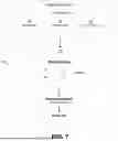
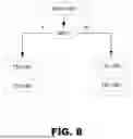
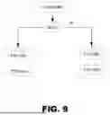


Sources:
- United States Patent and Trademark Office - verify current appl. status at the USPTO↗
Similar patent applications:
- » 20150066264
Methods and systems for hybrid driveline control - » 20150246669
Methods and systems for hybrid driveline control - » 20170015299
Method for controlling a hybrid driveline in order to optimize torque from a combustion engine arranged at the driveline - » 20170015305
Method for controlling a hybrid driveline - » 20170015300
Method for controlling a hybrid driveline in order to achieve gear change without interruption of torque - » 20210129828
Method and a control unit for controlling a hybrid driveline - » 20170015304
Method for controlling a hybrid driveline - » 20170028982
Method for controlling a hybrid driveline for reducing electrical losses - » 20170015307
Method for controlling a hybrid vehicle driveline - » 20170021819
Method for controlling a hybrid vehicle driveline
Recent applications in this class:
- » 20260054819 2026-02-26
CLOSED-LOOP AUTOMATIC CONTROL SYSTEM FOR SHIP SPEED AND METHOD THEREOF - » 20260048828 2026-02-19
JET PROPULSION BOAT AND METHOD OF CONTROLLING JET PROPULSION BOAT - » 20250368308 2025-12-04
PROPULSION ARRANGEMENT FOR MARINE VESSEL WITH CROSS-OVER FUNCTIONALITY - » 20250304232 2025-10-02
DUAL STEERING SYSTEM AND RELATED BOAT - » 20250289554 2025-09-18
INFORMATION PROCESSING METHOD AND PROGRAM - » 20250249996 2025-08-07
METHOD AND APPARATUS FOR CONTROLLING WATERJET-DRIVEN MARINE VESSEL - » 20250214694 2025-07-03
WATERCRAFT DEVICE WITH A HANDHELD CONTROLLER - » 20250206431 2025-06-26
PERSONAL WATERCRAFT AND CONTROLLING METHOD OF THE SAME - » 20250206430 2025-06-26
SYSTEM AND METHOD FOR OPERATING AN ELECTRIC VEHICLE BASED ON ACCELERATOR ACTUATION RATE - » 20250196987 2025-06-19
TROLLING MOTOR AND KICKER MOTOR MODE CONTROL
Recent applications for this Assignee:
- » 20260015072 2026-01-15
MARINE DRIVE UNIT - » 20260008471 2026-01-08
CONTROL UNIT AND METHOD THEREIN FOR DETECTING CHANGES IN OPERATION OF A POWERTRAIN OF A HEAVY-DUTY VEHICLE - » 20250376250 2025-12-11
MARINE INPUT DEVICE SATURATION - » 20250368308 2025-12-04
PROPULSION ARRANGEMENT FOR MARINE VESSEL WITH CROSS-OVER FUNCTIONALITY - » 20250360818 2025-11-27
METHOD FOR SAFELY ABORTING CHARGING OF A VEHICLE AND CHARGING STATION COMPRISING MEANS FOR SAFELY ABORTING CHARGING OF A VEHICLE - » 20250314214 2025-10-09
METHOD FOR OPERATING AN INTERNAL COMBUSTION ENGINE AN INTERNAL COMBUSTION ENGINE SYSTEM AND A VEHICLE - » 20250296657 2025-09-25
HULL UNIT WITH A HYDROFOIL SYSTEM AND MARINE VESSEL - » 20250282240 2025-09-11
COMMUNICATIONS INTERFACE, A COMMUNICATIONS SYSTEM AND A VEHICLE - » 20250214466 2025-07-03
COMMUNICATIONS MODULE, A COMMUNICATIONS SYSTEM AND A MARINE VESSEL - » 20250206429 2025-06-26
MARINE DRIVE UNIT