INSULATING CONTAINER
US20260054884A1
2026-02-26
18/815,023
2024-08-26
Smart Summary: An insulating container features two layers: an outer container and an inner container. The outer container has a tapered design and a handle, while the inner container fits inside it, leaving a gap in between. A special ceramic coating is applied to the inner surface of the inner container to help keep contents hot or cold. The container also has a removable lid with a mouth for a straw, making it easy to drink from. This design helps maintain the temperature of drinks and provides convenience for users. 🚀 TL;DR
Abstract:
Disclosed herein are systems and methods for a container having a ceramic coating. The container includes an outer container having a first wall extending from a top edge to a bottom edge, an inner container received within the outer container having a second wall with an upper edge below the top edge of the outer container, a gap formed between the inner and outer containers, a handle coupled to the outer container, and a lid removably engaged with at least one of the first and second walls. The first wall has an intermediate section tapering between upper and lower sections, the ceramic coating is applied to an inner surface of the second wall from a lower edge to the top edge of the first wall to line an interior volume. The lid includes a mouth configured to receive a straw and disposed adjacent a perimeter edge of the lid.
Inventors:
- Steve WHITWORTH 6 🇺🇸 Katy, TX, United States
- David FINDLAY 6 🇺🇸 Katy, TX, United States
- Rachel ROADES 1 🇺🇸 Katy, TX, United States
Applicant:
Interested in similar patents?
Get notified when new applications in this technology area are published.
Classification:
B65D25/14 » CPC main
Details of other kinds or types of rigid or semi-rigid containers Linings or internal coatings
A47G19/2205 » CPC further
Table service; Drinking vessels or saucers used for table service Drinking glasses or vessels
B65D47/0857 » CPC further
Closures with filling and discharging, or with discharging, devices; Closures with discharging devices other than pumps with pouring spouts or tubes; with discharge nozzles or passages having articulated or hinged closures made separately from the base element provided with the spout or discharge passage
B65D81/3869 » CPC further
Containers, packaging elements, or packages, for contents presenting particular transport or storage problems, or adapted to be used for non-packaging purposes after removal of contents with thermal insulation drinking cups or like containers formed with double walls, i.e. hollow
A47G19/22 IPC
Table service Drinking vessels or saucers used for table service
B65D47/08 IPC
Closures with filling and discharging, or with discharging, devices; Closures with discharging devices other than pumps with pouring spouts or tubes; with discharge nozzles or passages having articulated or hinged closures
B65D81/38 IPC
Containers, packaging elements, or packages, for contents presenting particular transport or storage problems, or adapted to be used for non-packaging purposes after removal of contents with thermal insulation
Description
BACKGROUND OF THE DISCLOSURE
Field of the Disclosure
The present disclosure relates to drinkware and, more specifically, to drinkware including a ceramic coating.
Description of the Background of the Disclosure
Beverage containers can be useful to transport, physically protect, thermally insulate, and consume various fluids. Fluid beverages are often enjoyed at cold temperatures and, thus, it is desired for beverage containers to thermally insulate the fluid beverages contained therein. Metallic materials are often used to construct beverage containers to provide durability and insulation. However, the metallic materials may alter the taste of the fluid beverages upon contact, which can produce undesirable tastes and sensations to a user when consuming the fluid beverage from the beverage container.
SUMMARY
Various aspects are described in connection with illustrative implementations of a container disclosed herein.
In some aspects, a beverage container includes an outer container having a first wall that extends continuously from a top edge to a bottom edge, wherein the outer container is made of metal. The beverage container includes an inner container that is received within and circumscribed by the outer container, the inner container having a second wall with an upper edge that is disposed below the top edge of the outer container, the second wall extending continuously from the upper edge to a lower edge that is adjacent an inner base, wherein the second wall is made of metal. An interior volume is defined between the top edge of the first wall and the inner base. The first wall has an intermediate section that tapers in diameter between an upper section and a lower section, the upper section having a substantially constant diameter between the top edge and the intermediate section, and the lower section defines a reduced diameter that is smaller than the constant diameter of the upper section. The beverage container includes a gap that is formed between the inner container and the outer container, wherein the gap extends between the upper edge and the bottom edge, and wherein the gap extends between the inner base and an outer base of the outer container. The beverage container includes a handle that is coupled to an outer surface of body section of the outer container, the handle having a lowermost point that is disposed above the waist section of the outer container. The beverage container includes a lid that is removably, sealingly engaged with at least one of the first wall and the second wall to cover the interior volume, the lid having a mouth that is configured to be selectively opened or closed and the mouth further being configured to receive a straw therethrough, wherein the mouth is disposed adjacent to a perimeter edge defined by the lid. A ceramic coating is applied to an inner surface of the second wall from the lower edge to a coating cutoff between the lower edge and the top edge of the first wall, inclusive, to line the interior volume.
According to some aspects, the lid further includes a flipper that is rotatable to selectively open and close the mouth. According to some aspects, the ceramic coating may comprise a composition including proportions of a polymethylsiloxane, silica sol dispersion, manganese ferrite spinel, water, aluminum oxide, and iron oxide red. According to some aspects, the ceramic coating may comprise multiple layers of the coating. According to some aspects, the coating cutoff may be between about 70% and about 100% of an inside surface height measured between the inner base and the top edge. According to some aspects, the coating cutoff may be between about 70% and about 90% of the inside surface height. According to some aspects, the coating may vary in thickness. According to some aspects, the coating cutoff may be disposed below a fastening portion that secures the lid to the container. According to some aspects, the outer base may seal a vacuum within the gap. According to some aspects, the lid may engage the first wall.
According to some aspects, a beverage container includes an outer container having a first wall that extends continuously from a top edge to a bottom edge, wherein the outer container is substantially cylindrical and defines a longitudinal axis through a centerpoint defined by the top edge, wherein the outer container is made of metal. The beverage container includes an inner container received within and circumscribed by the outer container, the inner container having a second wall with an upper edge that is disposed below the top edge of the outer container, the second wall extending continuously from the upper edge to a lower edge that is adjacent an inner base, wherein the second wall is made of metal. An interior volume is defined between the top edge of the first wall and the inner base. The beverage container includes a gap formed between the inner container and the outer container between the upper edge and the bottom edge. The beverage container includes a handle coupled to an outer surface of body section of the outer container, the handle having a lowermost point that is disposed above the bottom edge of the outer container. The beverage container includes a lid that is removably, sealingly engaged with at least one of the first wall and the second wall to cover the interior volume, the lid having an aperture that is configured to receive a straw therethrough, wherein the aperture is disposed adjacent to the longitudinal axis. A ceramic coating is applied to an entirety of an inner surface of the second wall from the lower edge to the upper edge and to an upper portion of an inner surface of the first wall to completely line the interior volume.
According to some aspects, the lid may further include a spout that is rotatable to selectively open and close the aperture. According to some aspects, the ceramic coating may comprise a composition including proportions of a polymethylsiloxane, silica sol dispersion, manganese ferrite spinel, water, aluminum oxide, and iron oxide red. According to some aspects, the ceramic coating may comprise multiple layers of the coating. According to some aspects, the coating may vary in thickness. According to some aspects, the outer base may seal a vacuum within the gap. According to some aspects, the lid may define an upper lid section and a lower lid section, and the lower lid section may define an inner diameter that is larger than an outer diameter of the first wall. According to some aspects, the second wall may taper between the upper edge and the lower edge. According to some aspects, the straw may be coupled to the lid. According to some aspects, the coating may be applied to a portion of the first wall.
Various alternative implementations of the foregoing aspects are disclosed. The foregoing various aspects may be combined in any manner without limitation. The foregoing and other aspects and advantages of the disclosure will appear from the following description. In the description, reference is made to the accompanying drawings, which form a part hereof, and in which there is shown by way of illustration a preferred configuration of the disclosure. Such configuration does not necessarily represent the full scope of the disclosure, however, and reference is made therefore to the claims herein for interpreting the scope of the disclosure.
BRIEF DESCRIPTION OF THE DRAWINGS
The present disclosure will be better understood and features, aspects, and advantages other than those set forth above will become apparent when consideration is given to the following detailed description thereof. Such detailed description makes reference to the following drawings.
FIG. 1 is a front elevation view of a container in a first configuration including a lid and a straw, according to an embodiment of the present disclosure;
FIG. 2 is a front isometric view of the container of FIG. 1, in a second configuration including an alternate style of lid;
FIG. 3 is a cross-sectional view of the container taken along the line III-III of FIG. 1, in a third configuration, shown without the straw;
FIG. 4 is an isometric view of a container in a first configuration including a lid, according to an embodiment of the present disclosure;
FIG. 5 is a cross-sectional view of the container taken along the line V-V of FIG. 4;
FIG. 6 is an isometric view of a container in a first configuration including a lid, according to an embodiment of the present disclosure;
FIG. 7 is a cross-sectional view of the container taken along the line VII-VII of FIG. 6, in the first configuration;
FIG. 8 is a front elevation view of a container in a first configuration including a lid, according to an embodiment of the present disclosure;
FIG. 9 is a cross-sectional view of the container showing a view that is normal to a plane defined along the line IX-IX of FIG. 8, in the first configuration;
FIG. 10 is an isometric view of the lid of the container of FIG. 8;
FIG. 11 is a front elevation view of a container in a first configuration including a lid and a straw, according to an embodiment of the present disclosure;
FIG. 12 is an isometric view of the container of FIG. 11, in a second configuration, shown without the lid and the straw;
FIG. 13 is a cross-sectional view of the container taken along the line XIII-XIII of FIG. 12, in the second configuration;
FIG. 14 is an isometric view of the lid of the container of FIG. 11;
FIG. 15 is an isometric view of a container in a first configuration including a lid, according to an embodiment of the present disclosure;
FIG. 16 is a cross-sectional view of the container showing a view that is normal to a plane defined along the line XVI-XVI of FIG. 14, in the first configuration;
FIG. 17 is an isometric view of a container in a first configuration including a lid, according to an embodiment of the present disclosure;
FIG. 18 is a cross-sectional view of the container showing a view that is normal to a plane defined along the line XVIII-XVIII of FIG. 17, in the first configuration;
FIG. 19 is an isometric view of a container in a first configuration including a lid, according to an embodiment of the present disclosure;
FIG. 20 is a cross-sectional view of the container showing a view that is normal to a plane defined along the line XX-XX of FIG. 19, in the first configuration;
FIG. 21 is a flow diagram of an example coating process, according to an embodiment of the present disclosure;
FIG. 22 is a flow diagram of an example manufacturing process, according to an embodiment of the present disclosure; and
FIG. 23 is a flow diagram of an example coating process, according to an embodiment of the present disclosure.
Before the embodiments of the disclosure are explained in detail, it is to be understood that the disclosure is not limited in its application to the details of construction and the arrangement of the components set forth in the following description or illustrated in the drawings. Aspects of the disclosure are capable of other embodiments and of being practiced or being carried out in various ways.
DETAILED DESCRIPTION OF THE DRAWINGS
FIGS. 1-3 illustrate an embodiment of a container 100, which may be configured as an insulating beverage container, according to aspects of the present disclosure. In some applications, the container 100 is configured for transport, protection, thermal insulation, and consumption of one or more fluid beverages. It should be understood, however, that the teachings herein are not limited to any particular beverage container, and are applicable to enclosures for containers of other products, including solids and liquids of various forms, temperatures, and compositions according to aspects of the present disclosure. In the illustrated embodiment, the container 100 includes an outer container 104, an inner container 108, and a gap 112 formed between the outer container 104 and the inner container 108. The container 100 also includes a handle 116 and a lid 120. As will be described below, in some embodiments, the container 100 may not include the handle 116, the lid 120, or both.
The container 100 defines a longitudinal axis L that extends through a geometric center of the container 100 (e.g., of the inner container 108) and an axial direction is defined along the longitudinal axis L. The longitudinal axis L extends centrally through a top end 124 and a bottom end 128 of the container 100. The container 100 has an upper section 132, an intermediate section 136, and a lower section 140. The upper section 132 extends from the top end 124 to the intermediate section 136, and the lower section 140 extends from the intermediate section 136 to the bottom end 128.
Referring to FIG. 3, in some aspects, the outer container 104 includes a first wall or outer wall 144 that extends continuously from a top edge 148 to a bottom edge 152. The outer wall 144 extends through the upper section 132, the intermediate section 136, and the lower section 140 of the container 100. In the illustrated embodiment, the outer wall 144 of the outer container 104 is cylindrical and rotationally symmetrical about the longitudinal axis L. The outer wall 144 defines a first diameter OD1 about the longitudinal axis L within the upper section 132. The first diameter OD1 is substantially constant or uniform between the top edge 148 and the intermediate section 136. Further, the outer wall 144 defines a second diameter OD2 about the longitudinal axis L within the intermediate section 136. The second diameter OD2 narrows or tapers inwardly toward the longitudinal axis L moving axially downward from the upper section 132 toward the lower section 140. The outer wall 144 further defines a lower diameter OD3 about the longitudinal axis L. The lower diameter OD3 tapers or narrows inwardly toward the longitudinal axis L moving axially downward from the intermediate section 136 to the bottom edge 152 of the container 100. The lower section 140 is configured to fit within a cup holder in, e.g., an automotive vehicle, watercraft, or stadium or auditorium seating. Accordingly, the lower diameter OD3 is provided in range of between about 2 inches and about 4 inches. The outer wall 144 defines an outer base 156 at the bottom end 128 of the container 100. The outer base 156 can be a planar, disc-shaped surface. It is appreciated that any of OD1, OD2, or OD3 can be an inner or outer diameter of the outer wall 144.
With reference to FIG. 1, the outer wall 144 of the outer container 104 includes an outer surface 160 that extends along the upper section 132, the intermediate section 136, and the lower section 140. The outer surface 160 includes a rim portion 164 that is disposed adjacent the top end 124 of the container 100. The rim portion 164 can be bounded axially between the top edge 148 and a transition line 168 that extends circumferentially about the longitudinal axis L. In some embodiments, an outer coating (not shown) is applied to the outer surface 160 below the transition line 168. In some embodiments, the outer coating (now shown) is not applied to the rim portion 164 above the transition line 168, such that the rim portion 164 defines a different surface finish than the outer surface 160 below the transition line 168. In other embodiments, the outer coating (not shown) is applied to one or more, two or more, or all of the upper section 132, the intermediate section 136, and the lower section 140.
The handle 116 is coupled to the outer wall 144 within upper section 132 and protrudes outwardly from the outer surface 160 in a direction, away from the longitudinal axis L, to define a handle opening 172. In particular, the handle 116 is provided in the form of a rotated, U-shaped element that is coupled to the outer surface 160 at an upper handle end 176 and a lower handle end 180. Both the upper handle end 176 and the lower handle end 180 are coupled to the outer wall 144 within the upper section 132 and disposed entirely, axially above the intermediate section 136 and the lower section 140. In some aspects, the handle 116 is formed of a plastic material, a metal material, or an organic material and is a separate component that is attached to the outer container 104. The upper handle end 176 and the lower handle end 180 may be secured to the outer wall 144 by using an adhesive, a fastener, a mechanical interlock, welding, or any suitable technique. The upper handle end 176 is arranged below the rim portion 164 of the outer wall 144 at the top end 124 of the outer container 104. In some embodiments, the handle 116 may be removably attached to the outer wall 144 by magnets, a mechanical interlock, an adhesive tape, fasteners, or any suitable method. In this way, the handle 116 can be repositioned or adjusted on the container 100 or may be removed entirely, as desired by the user. In some aspects, the handle 116 can be integrally formed with the outer container 104, so as to constitute a unitary component with the outer container 104. In some aspects, the handle 116 and the outer container 104 can be formed of the same materials or coated with the same materials. In some embodiments, the handle 116 and the outer container 104 are coated or treated with different materials from one another.
Referring again to FIG. 3, the inner container 108 includes a second wall or inner wall 184 that extends continuously from an upper edge 188 to an inner base 192. The inner wall 184 defines an interior volume 196 between the inner base 192 and the upper edge 188. The second wall 184 extends within the upper section 132, the intermediate section 136, and the lower section 140 of the container 100. The second wall 184 is received within and circumscribed by the outer container 104. The inner wall 184 defines a first diameter ID1 about the longitudinal axis L within the upper section 132. The first diameter ID1 is substantially constant or uniform between the upper edge 188 and the intermediate section 136. Further, the inner wall 184 defines a second diameter ID2 about the longitudinal axis L within the intermediate section 136. The second diameter ID2 narrows or tapers inwardly toward the longitudinal axis L moving axially downward from the upper section 132 toward the lower section 140. The inner wall 184 further defines a lower diameter ID3 about the longitudinal axis L. The lower diameter ID3 tapers or narrows inwardly toward the longitudinal axis L moving axially downward from the intermediate section 136 to the inner base 192 of the container 100. In some embodiments, the first inner diameter ID1 is equal to a maximum diameter of the second inner diameter ID2, while the lower diameter ID3 is equal to a minimum diameter of the second inner diameter ID2. It is appreciated that any of ID1, ID2, ID3, or ID4 can be an inner or outer diameter of the inner wall 184.
As described above, the gap 112 is formed between the inner container 108 and the outer container 104. In some embodiments, the gap 112 extends circumferentially around the longitudinal axis L between the inner container 108 and the outer container 104. As described above, the inner wall 184 of the inner container 108 and the outer wall 144 of the outer container 104 define diameters within the upper section 132, the intermediate section 136, and the lower section 140. It is appreciated that an outer diameter IOD of the inner wall 184 is less than an inner diameter OID of the outer wall 144 at any plane between the inner base 192 and the upper edge 188 that extends radially relative to the longitudinal axis L. The gap 112 therefore extends from the outer diameter IOD of the inner wall 184 to the inner diameter OID of the outer wall 144 between the inner base 192 and the upper edge 188. In some embodiments, the gap 112 extends below the inner base 192. Specifically, the gap 112 further extends from the inner base 192 of the inner wall 184 to the outer base 156 of the outer wall 144. In some embodiments, the gap 112 extends above the upper edge 188. Specifically, the gap 112 additionally extends from the engagement wall 228 to the outer wall 144 between the upper edge 188 and the top edge 148. It is therefore appreciated that an outer diameter EOD of the engagement wall 228 is less than an inner diameter OID of the outer wall 144 at any plane between the upper edge 188 and the top edge 148 that extends radially relative to the longitudinal axis L.
The gap 112 is substantially empty and void. In some embodiments, the construction of the inner container 108 and the outer container 104 is such that a vacuum is maintained within the gap 112. In some embodiments, the gap 112 is filled with insulative materials, such as, e.g., one or more fluids, one or more solids, one or more gases, or combinations thereof.
Referring to FIG. 2, the lid 120 is removably coupled at the top edge 148 to cover the interior volume 196 of the container 100. The lid 120 includes a gasket 204 and is configured to sealingly engage at least one of the inner wall 184 and the outer wall 144. As illustrated in FIG. 3, the lid 120 includes an upper lid section 208 having a first outer lid diameter OLD1 and a lower lid section 212 having a second outer lid diameter OLD2. The upper lid section 208 rests on the top edge 148. The second outer lid diameter OLD2 is smaller than the first outer lid diameter OLD1, allowing the lower lid section 212 to extend at least partially below the top edge 148 of the first wall 144 into the interior volume 196 between the top edge 148 of the outer wall 144 and the upper edge 188 of the inner wall 184. In some embodiments, the gasket 204 is disposed around the lower lid section 212. Additionally, the upper lid section 208 includes a mouth 216 that is configured to be selectively opened or closed to respectively allow or prevent access to the interior volume 196 through the lid 120.
As illustrated in FIG. 1, in some embodiments, the mouth 216 is configured to receive a straw 220 therethrough. The straw 220 allows the user to suck, pour, or otherwise move fluid from the interior volume 196 of the container 100 to the ambient environment. However, as illustrated in FIG. 2, in some embodiments, the upper lid section 208 includes the mouth 216 (as shown in FIG. 1) that is closable using a flipper 224. The flipper 224 is rotatably coupled to the lid 120 (e.g., the upper lid section 208). The flipper 224 can be rotated between an open position, in which the mouth 216 is not covered by the flipper 224, and a closed position, in which the mouth 216 is covered and sealed by the flipper 224. In some embodiments, the lid 120 is formed of a translucent or transparent material to provide a window for visibility into the interior volume 196. In some embodiments, the entire lid 120 is formed of a translucent or transparent material. In some embodiments, the lid 120 is at least partially opaque to conceal the contents within the interior volume 196 and/or to insulate the contents or interior portions of the container, e.g., the inner wall 184 or any coating applied thereto from light or heat. In some embodiments, the flipper 224 includes an engagement feature to secure the flipper 224 in the closed position. In some embodiments, the lid 120 is similar or identical to the lid described in U.S. patent application Ser. No. 18/233,772, which is incorporated herein by reference in its entirety.
In the illustrated embodiment of FIG. 3, the inner wall 184 includes an engagement wall 228 that extends between the top edge 148 of the outer wall 144 and the upper edge 188. Accordingly, the upper edge 188 flares outwardly relative to the longitudinal axis L to provide a smooth transition to the engagement wall 228. The engagement wall 228 defines a fourth diameter ID4 that is greater than the first diameter ID1 of the upper section 132 of the inner wall 184. Additionally, the fourth diameter ID4 is smaller than the first outer lid diameter OLD1 of the upper lid section 208, so that the upper lid section 208 can rest on the top edge 148. Furthermore, the fourth diameter ID4 is larger than the second outer lid diameter OLD2 of the lower lid section 212, so that the lower lid section 212 can extend into the container 100 and engage the engagement wall 228.
An inside surface 232 of the container 100 is defined along the inner wall 184 from the inner base 192 to the top edge 148 and includes the engagement wall 228. The inside surface 232 extends from the top edge 148 to the inner base 192, thereby surrounding and encompassing the interior volume 196 of the container 100. The inside surface 232 includes a fastening portion 236 between the top edge 148 and the upper edge 188 (e.g., along the engagement wall 228). The fastening portion 236 is configured to secure the lid 120 by engaging a corresponding fastening portion disposed around the lower lid section 212 (e.g., a threading, the gasket 204, or another known fastening mechanism). In some embodiments, the fastening portion 236 includes inner threading 240 disposed thereon and protruding inwardly toward the longitudinal axis L from the inside surface 232. In some embodiments, other types of fastening or closure mechanisms may be used, such as, e.g., an interlocking slot, and tab assembly. In some embodiments, the fastening portion 236 does not include any threading or fastener and, instead, a pressure-fit or interference fit is formed due to the relative dimensions of the inside surface 232 and the gasket 204 carried by the lid 120.
Still referring to FIG. 3, a coating 244 is applied to the inside surface 232 of the container 100. The coating 244 includes a layer of material that is applied to the inside surface 232 to line the interior volume 196 of the container 100. In some embodiments, the coating 244 is applied to the entirety of the inside surface 232 along the inner wall 184 and the outer wall 144, including along the inner base 192. Accordingly, the coating 244 extends continuously from the top edge 148 to the inner base 192 and completely surrounds and lines the interior volume 196. In some embodiments, the coating 244 is applied to the entirety of the inside surface 232 along the inner wall 184 and the outer wall 144, including along the inner base 192, as well as to a portion of the upper section 132 of the outer surface 160. For example, the coating 244 can be also applied to a top half of the upper section 132 of the outer surface 160. As illustrated in FIG. 3, in some embodiments, the coating 244 is not applied to the inside surface 232 above the upper edge 188, such as along the fastening portion 236 or along the engagement wall 228, but the coating 244 is applied to the inside surface 232 along the inner wall 184. Accordingly, the coating 244 extends continuously from the upper edge 188 to the inner base 192 and completely surrounds and lines the interior volume 196. In some embodiments, the coating 244 is not applied to the engagement wall 228 to reduce the risk of the coating 244 cracking to do frequent rubbing or other mechanical abrading caused by securing and removing the lid 120.
In some embodiments, the coating 244 is applied to the inside surface 232 between the inner base 192 and a coating cutoff 248, inclusive, which is disposed between the inner base 192 and the top edge 148. The coating cutoff 248 extends around the inside surface 232 along a plane that extends radially relative to the longitudinal axis L. In some embodiments, the coating cutoff 248 is disposed a coating distance 252 from the inner base 192 that is between about 50% and about 100% of an inside surface height 256 measured between the inner base 192 and the top edge. In some embodiments the coating distance 252 is between about 60% and about 100%, or about 60% and about 90%, or about 70% and about 100%, or between about 70% and about 90% of the inside surface height 256. In some embodiments, the coating cutoff 248 is disposed below the engagement wall 228 and the fastening portion 236 disposed thereon.
In some embodiments, the coating 244 contains multiple layers, such as, e.g., a first layer, a second layer, a third, layer, or a fourth layer, or more. In some embodiments, the coating 244 is applied discontinuously along the inside surface 232, such that there are areas or regions in which the coating 244 is absent. In some embodiments, the coating 244 varies in thickness T along the inside surface 232. In some aspects, the coating 244 is a composition including various proportions of a polymethylsiloxane, silica sol dispersion, manganese ferrite spinel, water, aluminum oxide, and iron oxide red, as illustrated in Table 1 below.
| Ingredients | By Weight | |
| polymethylsiloxane | 30-36 | |
| silica sol dispersion | 16-20 | |
| manganese ferrite spinel | 19 | |
| water | 13-17 | |
| aluminum oxide | 6 | |
| iron oxide red | 12 | |
Referring briefly to FIG. 21, an example flow diagram for a coating process is depicted, which may be performed to a apply a coating to a container e.g., the coating 244 to the container 100. Step S100 includes cleaning, roughening, or otherwise preparing a surface of a container, such as the container 100. In some embodiments, cleaning or roughening the surface of the container can include pressure washing, sandblasting, abrasive blasting, mechanically sanding, using a degreaser, or using a chemical cleaner. Step S104 includes applying a ceramic coating to a desired surface of the container. As discussed above, the coating 244 can be applied to all of or a portion of the inner wall 184 or the outer wall 144 of the container 100. Additionally, the coating 244 can be applied to the container 100 using a variety of techniques including spraying, wiping, pouring, brushing, or other techniques of applying a liquid to a surface. As such, the coating 244 can be applied by a sprayer, a brush, a roller, an applicator pad, a funnel, or another type of liquid applicator. In some embodiments, during the coating process, excess amounts of the coating 244 can be removed using a cloth, a vacuum, a squeegee, or another known tool for absorbing or moving a fluid solution. The excess coating can then be recycled and reused for coating another container.
Step S108 includes drying the coating on the container at a predetermined temperature for a predetermined amount of time. Step S112 is a decision step at which the container and coating are inspected for defects. If the container or coating includes a defect, i.e., decision=YES, the method continues to step S116. If the container or coating does not include a defect, i.e., decision=NO, the method continues to step S120. The container 100 or the coating 244 can be inspected by a human or machine operator. For example, a surface of the container 100 or the coating 244 can be checked for scratches, cracks, dents, coating thickness, consistency of coating thickness, and other factors using sensors.
Step S116 is a decision step at which it is determined if the defect is repairable. If the defect is repairable, i.e., decision=YES, the method proceeds to step S124 where the defect is repaired, and continues on to step S120. If the defect is not repairable, i.e., decision=NO, the method proceeds to step S128 where the container is discarded.
Step S120 is also a decision step at which it is determined if the container requires another layer of the coating. If the container requires another layer of the coating, i.e., decision=YES, the method returns to step S104, and another layer of the coating is applied. If the container does require another layer of the coating, i.e., decision=NO, Step S132 includes polishing the container and coating. The container 100 can be polished using chemicals and a brush, cloth, or other applicator.
Step S136 includes marking the outer wall of the container with indicator(s). For example, the indicator can mark the containers that include or will include the ceramic coating. The indicator can be used by a machine or human operator throughout the manufacturing process. For example, after the indicator is applied, a conveyor system and any detectors thereof (e.g., human or machine) can identify and sort coated containers from uncoated containers. As described further below, indicator(s) can be a logo, a symbol, a design, and/or a pattern that can be applied using a variety of techniques.
In some embodiments, the indicator(s) are located on the outer wall, in any of an upper section, lower section, or intermediate section of the container. In some embodiments, the indicator(s) are applied using an adhesive, an engraver, a paint, a color contrast coating, an abrasion tool (such as a knurling tool to create a texture on the outer wall or exterior coating), or other technique of marking a surface. In some embodiments, the container includes an exterior coating along the outer wall thereof, and the indicator(s) are engraved (e.g., laser engraved, engraved with a cutting tool, or otherwise engraved) by removing one or more layers of the coating on the exterior wall.
In some embodiments, a color of one or more of the logo, symbol, design, or pattern indicator(s) is used to indicate the presence of the coating to the machine or human operator. For example, if the color of one or more of the logo, design, or pattern indicator(s) does not match a color of the exterior coating that covers the outer wall, the container may include the interior ceramic coating. In other examples, the presence of the indicator(s) that are a specific design or symbol indicates that the container includes the ceramic coating.
As described above, the indicator(s) can be detected by a human or machine detector. In some embodiments, the indicator(s) can be detected by a camera that is positioned adjacent a conveyor system transporting the container. Specifically, the camera can scan the outer wall of the container and determine if the container includes the ceramic coating. The camera can then communicate with the conveyor system transporting the container, to route the container to a correct fulfillment (e.g., packaging) station.
In some embodiments, after the container is polished, and prior to the container being marked with the indicator, the container is added to a marking system for marking the container with the indicator(s) or other logos, symbols, and designs. In some embodiments, the marking system includes a camera that is positioned adjacent a conveyor system of the marking system. The camera can detect a presence, or lack thereof, of the ceramic coating within the container. For example, the camera can measure a surface finish characteristic, such as light reflectivity, that differs between coated and uncoated surfaces. The camera can then communicate with the marking system to ensure that the containers including the ceramic coating, are marked with the indicator(s).
As described above, the container 100 can advantageously be coated with multiple layers of the coating 244 to increase a durability of the coating 244. For example, providing multiple layers of the coating can reduce a likelihood of cracking, scratching, or otherwise breaking through the coating 244 to the surface of the inner wall 184 or the outer wall 144 of the container 100 underneath the coating. In some embodiments, a number of layers of the coating 244 to be applied to the container 100 is predetermined by a procedure stored in a memory of a human or machine operator. In other examples, layers of the coating 244 are applied to the container 100 until the coating 244 is sufficiently thick (e.g., determined by a sensor controlled by the human or machine operator).
In some embodiments, throughout the method of FIG. 21 one or more layers of the coating 244 are applied to different areas of the surface of the container 100. For example, a first layer of the coating 244 can be applied to a first area extending from the inner base 192 to the top edge 148, while a second layer of the coating 244 can be applied to a second area extending from the upper edge 188 to the top edge 148, to increase a durability of the coating 244 in high contact areas, such as the engagement wall 228. It is appreciated that the first and second areas can overlap or can instead be disconnected. It is additionally appreciated that layers of the coating 244 can be applied to any number of different areas of the container 100.
FIG. 22 depicts an example flow diagram for a manufacturing process, which may be performed to assemble a container and apply a ceramic coating thereto, e.g., the coating 244 to the container 100. Step S200 includes forming an inner container and an outer container of a double walled container, such as the inner container 108 and the outer container 104 of the container 100. Step S204 includes vacuum sealing a gap between the inner container and the outer container, using a seal, at a first predetermined temperature, such as the outer base 156 sealing the container 100. It is appreciated that the outer base 156 can be a variety of materials including rubber, silicone, or metal. A rubber or silicone outer base 156 could be melted to the outer container 104 to seal the vacuum within the gap 112, while a metal outer base 156 could be welded to seal the vacuum within the gap 112. Step S208 including preparing a surface of the container. Step S212 includes marking the container with an indicator. Step S216 includes applying a ceramic coating on the container. Step S220 includes drying the coating on the container at a second predetermined temperature. It is appreciated that the second predetermined temperature is less than the first predetermined temperature. The second predetermined temperature being less than the first predetermined temperature ensures that the outer base 156, or other seal, does not mistakenly melt or otherwise compromise the vacuum seal. Step S224 includes polishing the container and the coating.
In some embodiments, the indicator applied in step S212 can mark the containers that will be coated with the ceramic coating in step S216. The indicator can be used by a machine or human operator throughout the manufacturing process. For example, after the indicator is applied, a conveyor system and any detectors thereof (e.g., human or machine) can identify and sort coated containers from uncoated containers. As described further below, indicator(s) can be a logo, a symbol, a design, and/or a pattern.
In some embodiments, the indicator(s) are located on the outer wall, in any of an upper section, lower section, or intermediate section of the container. In some embodiments, the indicator(s) are applied using an adhesive, an engraver, a paint, a color contrast coating, an abrasion tool (such as a knurling tool to create a texture on the outer wall or exterior coating), or other technique of marking a surface.
As described above, the indicator(s) can be detected by a human or machine detector. In some embodiments, the indicator(s) can be detected by a camera that is positioned adjacent a conveyor system that is transporting the container. Specifically, the camera can scan the container for the indicator(s) and determine if the container should be lined with the ceramic coating. If the indicator(s) are detected, the camera can then communicate with the conveyor system transporting the container, to route the container to a coating station for application of the ceramic coating.
Adding the indicator(s) to the containers prior to coating can enable the conveyor system to identify and direct those containers that are destined to be coated to the coating station while other containers, that do not include the indicator(s), are directed away from the coating station. As a result, the coating station can be integrated into the conveyor system (e.g., with an existing conveyor system), and the use of automation can enable faster and more efficient manufacturing assembly lines.
FIG. 23 depicts an example flow diagram for an automated coating process, which may be performed to automate the application of a coating to a container, e.g., the coating 244 to the container 100. Step S300 includes adding a container to a coating system, such as the container 100. Step S304 includes scanning a code associated with the container 100 (e.g., attached thereto) to recognize a type of the container (e.g., a size, shape, color, or other defining detail of the container) and communicate the type of the container to the coating system. Step S308 includes conveying the container along a conveyance system to a coating chamber, such as the container 100. Step S312 includes extending an automated coating arm into an internal volume of the container and rotating or translating the coating arm or the container as a coating is dispensed from the coating arm onto a desired area of an internal surface of the container, such as applying the coating 244 onto the inner wall 184 of the container 100.
In some embodiments, the desired area of the inner wall 184 of the container 100 to be coated, and therefore a movement of the container relative to the automated arm, or movement of the coating arm, to coat the desired area, is based on the type of the container 100 that is being coated. For example, data regarding the specific areas to be coated can be stored within the coating system, and associated with the type of the container 100. The coating system can then control movement of the coating arm and dispensation of the coating to precisely coat one or more areas of the container as specified by the data associated with the type of the container 100. It is appreciated that the coating 244 can be applied using a sprayer, a brush, a roller, or another automated coating mechanism for applying a coating to a surface. Additionally, it is appreciated that the coating chamber can be climate controlled for temperature and humidity to ensure proper application of the coating 244.
Step S316 includes extending a second automated coating arm to an exterior of the container and rotating or otherwise moving the coating arm or the container as a coating is dispensed from the second coating arm onto an external surface of the container, such as applying the coating 244 onto the outer wall 144 of the container 100. Similar to the application of the coating 244 to the inner wall 184, the coating system can control movement of the second coating arm or the container and dispensation of the coating 244 to coat a specific area of the container 100 based on the data associated with the type of the container 100. Additionally, it is appreciated that the coating 244 can be applied using a sprayer, a brush, a roller, or another automated coating mechanism for applying a coating to a surface.
Step S320 includes wiping, squeegeeing, or otherwise removing excess coating from the surface of the container. In some embodiments, the removed excess coating can be reloaded into the first or second coating arms and reapplied to another container. Step S324 includes conveying the container to a drying chamber and drying the coating on the container. Step S328 includes conveying the container to a packaging station to be packaged and shipped to a user.
Turning back to FIGS. 4 and 5, another embodiment of a container 300 includes a longitudinal axis L2, an outer container 304, an inner container 308, a gap 312, a lid 320, an upper section 332, an intermediate section 336, a lower section 340, a top edge 348, an upper edge 388, an engagement wall 428, a fastening portion 440, an inner base 392, an outer base 356, an interior volume 396, and a coating 444. The outer container 304 includes an outer wall 344 and the inner container 308 includes the inner wall 384 that extend between the upper section 332, the intermediate section 336, and the lower section 340. The lid 320 includes an upper lid section 408, a lower lid section 412, and a gasket 404 surrounding the lower lid section 412. In this embodiment, elements that are shared with—i.e., that are structurally and/or functionally identical to—elements present in the first embodiment of the container 100 are represented by equivalent reference numerals. Thus, discussion of the container 100 above also generally applies to similarly numbered or named components of the container 300 (and vice versa).
The illustrated container 300 of FIGS. 4 and 5 defines a different shape than the container 100 of FIGS. 1-3. Additionally, the container 300 of FIGS. 4 and 5 includes a different configuration of the lid 320 as compared to the container 100 of FIGS. 1-3.
Referring to FIG. 5, the outer wall 344 defines a first diameter OD12 about the longitudinal axis L2 within the upper section 332. The first diameter OD12 is substantially constant or uniform between the top edge 348 and the intermediate section 336. Further, the outer wall 344 defines a second diameter OD22 about the longitudinal axis L2 within the intermediate section 336. The second diameter OD22 widens or tapers outwardly away from the longitudinal axis L2 moving axially downward from the upper section 332 toward the lower section 340. The outer wall 344 further defines a lower diameter OD32 about the longitudinal axis L2. The lower diameter OD32 is substantially constant or uniform between the intermediate section 336 and the bottom edge 352 of the container 300. Additionally, at least a portion of the outer wall 344 within the lower section 340 varies in a wall thickness (i.e., a dimension measured between and perpendicular to the outer surface and the inner surface of the outer wall).
Still referring to FIG. 5, the second wall or inner wall 384 defines a first diameter ID12 about the longitudinal axis L2 within the upper section 332. The first diameter ID12 is substantially constant or uniform between the upper edge 388 (e.g., a bottom of the fastening portion 440) and the intermediate section 336. Further, the inner wall 384 defines a second diameter ID22 about the longitudinal axis L2 within the intermediate section 336. The second diameter ID22 widens or tapers outwardly away from the longitudinal axis L22 moving axially downward from the upper section 332 toward the lower section 340. The inner wall 384 further defines a lower diameter ID32 about the longitudinal axis L2. The lower diameter ID32 is substantially constant or uniform between the intermediate section 336 and the inner base 392 of the container 300. In some embodiments, the first inner diameter ID12 is equal to a minimum diameter of the second inner diameter ID2, while the lower diameter ID3 is equal to a maximum diameter of the second inner diameter ID2.
The inner wall 384 includes the engagement wall 428 that extends between the top edge 348 of the outer wall 344 and the upper edge 388. The engagement wall 428 defines a fourth diameter ID42 that is equal to the first diameter ID12 of the inner wall 384, so that the upper section 332 of the inner wall 384 defines a constant or uniform diameter. Still referring to FIG. 5, the lid 320 includes a first outer lid diameter OLD12 of the upper lid section 408, that is greater than the first diameter OD12 so that the upper lid section 408 can rest on the top edge 348. Furthermore, the fourth diameter ID42 is larger than a second outer lid diameter OLD22 of the lower lid section 412, so that the lower lid section 412 can extend into the container 300 and engage the engagement wall 428.
As illustrated in FIG. 5, a mouth 416 of the lid 320 is disposed adjacent a perimeter of the upper lid section 408. Additionally, in some embodiments, the mouth 416 of the lid 320 includes a spout 460. The spout 460 includes an upper spout section 464 that is rotatably coupled to the upper lid section 408. The upper spout section 464 is rotatable between an open position and a closed position. The spout 460 further includes a lower spout section 468 that extends into the interior volume 396 of the container 300 to allow fluid to flow from the container 300 through the spout 460 to the ambient environment.
In some embodiments, spout channels extending through the spout 460 taper between the upper spout section 464 and the lower spout section 468. Specifically, the spout channel in the upper spout section 464 may define a larger diameter than the spout channel in the lower spout section 468. This taper can provide smoother flow of fluids through the spout 460 and the spout channel. In some embodiments, a straw or other conduit (not shown) is connected to the lower spout section 468. The straw (not shown) can allow the spout 460 to access and convey fluids disposed in the lower section 340 of the container 300. In particular, a top end of the straw is removably press fit onto the lower spout section 468. The straw can abut the inner bottom of the lid 320 (e.g., a bottom of the upper lid section 408) to form a pressure-tight seal that minimizes or eliminates any intake of air or fluid from the top end of the straw when a user sucks through the spout 460, thereby concentrating the suction at the bottom end of the straw to maximize fluid extraction/dispensing from the container 300.
In some embodiments, the straw can be a straight, linear straw that extends parallel to the axis L2 from the lid 320 to the lower section 340 (e.g., to the inner base 392). In some embodiments, the straw can be sized or shaped to extend linearly or curvilinearly to be disposed at an oblique angle relative to the axis L2. The spout channel extending through the upper spout section 464 is designed to be selectively aligned with the spout channel extending through the lower spout section 468. As described above, the upper spout section 464 is rotatable between an open position and a closed position by engaging the engagement arm 470. In some embodiments, in the open position where the straw and the channels of the spout sections 464, 468 are aligned, the engagement arm 470 is sized and shaped to abut a recessed wall on an exterior side of the lid 320. This way, the maximum rotational distance of the spout 460 (e.g., the upper spout section 464) corresponds to full alignment and unrestricted flow of fluid through the straw and spout channels. It is also designed so that a partial rotational distance, i.e., rotating the spout 460 (e.g., the upper spout section 464) less than its full extent, causes partial alignment between the straw and the spout channels, to provide a reduced or restricted flow configuration. However, to avoid accidental or unintended leaking or dispensing of fluid from the spout 460, the partial rotation may be greater than 50% of the full rotational distance before fluid will flow through the spout channels. Additionally, in some embodiments, the lower spout section 468 is sized and shaped to prevent fluid from flowing around it, whether in the seated/closed position, the fully open position, or any partially rotated position.
It is also preferable that when the spout 460 is in the fully open position, the spout 460 extends obliquely outwardly relative to the axis L2 so that the outlet end of the spout channel (e.g., an end of the upper spout section 464 that is opposite the lower spout section 468) is positioned a greater distance from the axis L2 than the exterior surface of the lid 320. This position enables a user to have unobstructed access to the outlet of the spout channel. In some embodiments, when fully open, the outlet end of the spout channel is coextensive with the outer diameter OD32 of the lower section 340 of the outer wall 344. In some embodiments, when fully open, the outlet end of the spout is positioned a greater distance from the axis L2 than the exterior surface of the outer wall 344 in the lower section 340.
In some embodiments, the spout 460 includes an engagement arm 470 that a user can manipulate to rotate the upper spout section 464 between the open and closed position. Additionally, the lid 320 can include a hole 472 that is open while the spout 460 is in the open position and closed while the spout 460 is in the closed position. The hole 472 allows ambient air to flow into the container 300 to promote pressure equalization between the ambient environment and the interior volume 396 for a consistently smooth flow of fluid out of the container 300 through the spout 460.
Still referring to FIG. 5, the coating 444 of the container 300 extends from the inner base 392 to the upper edge 388. The coating 444 is therefore not applied to the engagement wall 428 to reduce the risk of the coating 444 cracking to do frequent rubbing or other mechanical abrading caused by securing and removing the lid 320. As illustrated in FIG. 5, the outer base 356 comprises a high-friction material such as rubber, silicone, or other known high friction material. The outer base 356 can be configured to contact a surface (not shown) on which the container 300 is resting to mitigate sliding or other movement of the container 300 across the surface.
FIGS. 6 and 7 illustrate another embodiment of a container 500 that includes a longitudinal axis L3, an outer container 504, an inner container 508, a gap 512, a lid 520, an upper section 532, an intermediate section 536, a lower section 540, a top edge 548, an engagement wall 628, a fastening portion 640, an inner base 592, an outer base 556, an interior volume 596, and a coating 644. The outer container 504 includes an outer wall 544 and the inner container 508 includes the inner wall 584 that extend between the upper section 532, the intermediate section 536, and the lower section 540. The lid 520 includes an upper lid section 608, a lower lid section 612, and a gasket surrounding the lower lid section 612. In this embodiment, elements that are shared with—i.e., that are structurally and/or functionally identical to—elements present in the previous embodiments of the container 100, 300 are represented by equivalent reference numerals. Thus, discussion of the container 100 above also generally applies to similarly numbered or named components of the container 300 (and vice versa). Thus, discussion of the container 100, 300 above also generally applies to similarly numbered or named components of the container 500 (and vice versa).
The illustrated container 500 of FIGS. 6 and 7 defines a different shape than the container 100 of FIGS. 1-3 and the container 300 of FIGS. 4 and 5. Additionally, the lid 520 of the container 500 of FIG. 6 is different than the lids 120, 320 of the containers 100 of FIGS. 1-3 and the container 300 of FIGS. 4 and 5.
Referring to FIG. 7, the outer wall 544 defines a first diameter OD13 about the longitudinal axis L3 within the upper section 532. The first diameter OD13 is substantially constant or uniform between the top edge 548 and a neck 676 of the container 500. The neck 676 is disposed within the upper section 532 and defines a second diameter OD23 about the longitudinal axis L3 within the upper section 532. The second diameter OD23 is larger than the first diameter OD13 and is substantially constant or uniform between the neck 676 and the intermediate section 536. Further, the outer wall 544 defines a third diameter OD33 about the longitudinal axis L3 within the intermediate section 536. The third diameter OD33 widens or tapers outwardly away the longitudinal axis L3 moving axially downward from the upper section 532 toward the lower section 540. The outer wall 544 further defines a lower diameter OD43 about the longitudinal axis L3. The lower diameter OD43 is substantially constant or uniform between the intermediate section 536 and the bottom edge 552 of the container 500.
Still referring to FIG. 7, the second wall or inner wall 584 defines a first diameter ID13 about the longitudinal axis L3 within the upper section 532. The first diameter ID13 is substantially constant or uniform between the top edge 548 and the intermediate section 536. Further, the inner wall 584 defines a second diameter ID23 about the longitudinal axis L within the intermediate section 536. The second diameter ID23 widens or tapers outwardly away from the longitudinal axis L3 moving axially downward from the upper section 532 toward the lower section 540. The inner wall 584 further defines a lower diameter ID33 about the longitudinal axis L3. The lower diameter ID33 is substantially constant or uniform between the intermediate section 536 and the inner base 592 of the container 500.
In the present embodiment, the outer wall 544 includes the engagement wall 628 that extends between the top edge 548 of the outer wall 544 and the neck 676. The engagement wall 628 includes the fastening portion 640. The fastening portion 640 is configured to secure the lid 520 by engaging a corresponding fastening portion disposed around the lower lid section 612 (e.g., a threading, a gasket (not shown), or another known fastening mechanism). In some embodiments, the fastening portion 640 includes threading disposed thereon and protruding outwardly from the longitudinal axis L3 from the outer wall 544. In some embodiments, other types of fastening or closure mechanisms may be used, such as, e.g., an interlocking slot, and tab assembly. In some embodiments, the fastening portion 640 does not include any threading or fastener and, instead, a pressure-fit or interference fit is formed due to the relative dimensions of the outer wall 544 and sections of the lid 120.
Still referring to FIG. 7, the lid 520 includes a first outer lid diameter OLD13 of the upper lid section 608 that is greater than the first diameter OD13, so that the upper lid section 608 can rest on the top edge 548. Additionally, in some embodiments, the lower lid section 612 includes a central cavity extending from a lower edge of the lower lid section 612 to the upper lid section 608. The central cavity allows the lower lid section 612 to be inserted over the upper section 532 of the container 500. Specifically, the first diameter OD13 is smaller than a first inner lid diameter ILD13 of the lower lid section 612, so that the lower lid section 612 can extend around the engagement wall 628 of the container 500.
Referring briefly to FIG. 6, the upper lid section 608 of the illustrated embodiment in FIG. 6, includes a mouth that is closable using a flipper 624. In some embodiments, the upper lid section 608 further includes a handle 692 to allow a user to carry the container 500. When installed on the container 500, the handle 692 is coupled to a first side of the lid 520 and a second side of the lid 520 that is radially opposite the first side about the longitudinal axis L3. The handle 692 is coupled to the lid 520 utilizing mechanical fasteners (e.g., screws, or other known fasteners). The handle 692 can be rotatable about the lid 520 to allow the container 500 and lid 520 to be easily carried and stored.
In some embodiments, the handle 692 may be secured to the lid 520 by using an adhesive, a fastener, a mechanical interlock, welding, or any suitable technique. In some embodiments, the handle 692 may be removably attached to the lid 520 by magnets, a mechanical interlock, an adhesive tape, fasteners, or any suitable method. In this way, the handle 692 can be repositioned or adjusted on the lid 520 or may be removed entirely, as desired by the user. In some aspects, the handle 692 can be integrally formed with the lid 520, so as to constitute a unitary component with the lid 520. In some aspects, the handle 692 and the lid 520 can be formed of the same materials or coated with the same materials. In some embodiments, the handle 692 and the lid 520 are coated or treated with different materials from one another.
Referring again to FIG. 7, the coating 644 of the container 500 extends from the inner base 592 to the top edge 548. In the illustrated embodiment, as the fastening portion 640 is disposed on an exterior surface of the container 500, the coating 644 can be applied to an entirety of an interior surface of the container 500 without risk of frequent rubbing or other mechanical abrading caused by securing and removing the lid 320. In some embodiments, mitigating abrasion to the coating 644 on the engagement wall 628 allows the coating 644 to extend from the inner base 592 to the top edge 548, and advantageously reduces contact of the fluid within the container 500 with metal surfaces of the container 500, potentially leading to a better tasting beverage retained within the container 500.
FIGS. 8-10 illustrate another embodiment of a container 700 that includes a longitudinal axis L4, an outer container 704, an inner container 708, a gap 712, a lid 720, an upper section 732, an intermediate section 736, a lower section 740, a top edge 748, an upper edge 788, an engagement wall 828, a fastening portion 840, an inner base 792, an outer base 756, an interior volume 796, a gasket 804, and a coating 844. The outer container 704 includes an outer wall 744 and the inner container 708 includes the inner wall 784 that extends between the upper section 732, the intermediate section 736, and the lower section 740. The lid 720 includes an upper lid section 808, a lower lid section 812, and a gasket surrounding the lower lid section 812. In this embodiment, elements that are shared with—i.e., that are structurally and/or functionally identical to—elements present in the previous embodiments of the container 100, 300, 500 are represented by equivalent reference numerals. Thus, discussion of the container 100, 300, 500 above also generally applies to similarly numbered or named components of the container 700 (and vice versa).
The illustrated container 700 of FIGS. 8-10 defines a different shape than the container 100 of FIGS. 1-3, the container 300 of FIGS. 4 and 5, and container 500 of FIGS. 6 and 7. Additionally, the container 700 of FIGS. 8-10 and includes a different configuration of the lid 720 as compared to the container 100 of FIGS. 1-3, the container 300 of FIGS. 4-5, and the container 500 of FIGS. 6 and 7.
Referring to FIG. 9, in many aspects, the container 700 defines a profile or shape that is similar to the container 300, including the outer container 704 and the inner container 708 that define substantially constant or uniform diameters within the upper section 732, outward tapered diameters within the intermediate section 736, and substantially constant or uniform diameters again in the lower section 740. Additionally, the outer container 704 and the inner container 708 define similar positioning of the engagement wall 828, and similar engagement interaction between the engagement wall 828 (e.g., the fastening portion 840 thereof) and the lower lid section 812. However, the container 700 generally defines larger dimensions than the container 300. Specifically, the inner container 708, the outer container 704, and the lid 720 define larger diameters at least at the upper section 732, the intermediate section 736, the lower section 740, and the top edge 748 than similarly numbered components of the container 300. As such, the container 700 can advantageously hold more fluid.
Referring to FIGS. 8-10, the lid 720 includes the upper lid section 808 that rests on the top edge 748, and the lower lid section 812 that extends into the interior volume 796 of the container 700, when the lid 720 is installed on the container 700. The upper lid section 808 includes a handle 892 to allow a user to carry the container 700. When installed on the container 700, the handle 892 is coupled to a first side of the lid 720 and a second side of the lid 720 that is radially opposite the first side about the longitudinal axis L4. The handle 892 is coupled to the lid 720 utilizing mechanical fasteners (e.g., screws, or other known fasteners). The handle 892 is rotatable relative to the lid 720, such that the handle 892 can be rotated downward toward the outer base 756 of the container 700 to be disposed substantially below the lid 720, which provides easier access for dispensing or consuming contents through the lid 720 and affords a shorter total height of the container for facilitating storage in compact spaces. Further, the handle 892 can be rotated upward to be above the lid 720, as illustrated in FIGS. 8 and 9, to allow the container 700 and lid 720 to be easily carried by hand or attached to external objects, such as, e.g., a vehicle, cooler, or backpack.
In some embodiments, the handle 892 may be secured to the lid 720 by using an adhesive, a fastener, a mechanical interlock, welding, or any suitable technique. In some embodiments, the handle 892 may be removably attached to the lid 720 by magnets, a mechanical interlock, an adhesive tape, fasteners, or any suitable method. In this way, the handle 892 can be repositioned or adjusted on the lid 720 or may be removed entirely, as desired by the user. In some aspects, the handle 892 can be integrally formed with the lid 720, so as to constitute a unitary component with the lid 720. In some aspects, the handle 892 and the lid 720 can be formed of the same materials or coated with the same materials. In some embodiments, the handle 892 and the lid 720 are coated or treated with different materials from one another.
Referring to FIGS. 9 and 10, in some embodiments, a mouth 816 of the lid 720 includes a spout 860 that allows fluid to flow from the interior volume 796 to the ambient environment. The spout 860 extends from an upper surface of the upper lid section 808. The spout 860 is closable by a cap 884. The cap 884 is secured to the spout 860 via a threaded engagement, a friction engagement, a snap engagement, or any other known engagement. In some embodiments, a closure mechanism of the cap 884 extends into the spout 860, and a threading disposed around an outer diameter of the closure mechanism engages a threading disposed around an inner diameter of the spout 860 to secure the cap 884 to the spout 860.
The cap 884 is secured to the lid 720 using an arm 824 (see FIG. 10). The arm 824 is coupled at a first end to the cap 884 and at a second end to the lid 720. The arm 824 can be flexible to allow the arm 824 to be bent and the cap 884 to be moved from an open position, in which the spout 860 is not covered by the cap 884, and a closed position, in which the mouth (not shown) is covered and sealed by the cap 884. Additionally, the arm 824 can be rotated relative to the lid 720 about a coupling that secures the arm 824 to the lid 720. Specifically, the arm 824 can rotate along a plane that extends about radially relative to the longitudinal axis L4, to provide the user multiple degrees of freedom for moving the arm 824 and the cap 884.
Referring briefly again to FIG. 9, the coating 844 of the container 700 extends from the inner base 792 to the upper edge 788. The coating 844 is therefore not applied to the engagement wall 828 to reduce the risk of the coating 844 cracking to do frequent rubbing or other mechanical abrading caused by securing and removing the lid 720.
FIGS. 11-13 illustrate another embodiment of a container 900 that includes a longitudinal axis L5, an outer container 904, an inner container 908, a gap 912, a lid 920 (see FIG. 14), an upper section 932, an intermediate section 936, a lower section 940, a top edge 948, an upper edge 988, an engagement wall 1028, a fastening portion 1040, an inner base 992, an interior volume 996, and a coating 1044. The outer container 904 includes an outer wall 944 and the inner container 908 includes the inner wall 984 that extend between the upper section 932, the intermediate section 936, and the lower section 940. The lid 920 includes an upper lid section 1008, a lower lid section 1012, and a gasket surrounding the lower lid section 1012. In this embodiment, elements that are shared with—i.e., that are structurally and/or functionally identical to—elements present in the previous embodiments of the container 100, 300, 500, 700 are represented by equivalent reference numerals. Thus, discussion of the container 100, 300, 500, 700 above also generally applies to similarly numbered or named components of the container 900 (and vice versa).
Referring to FIGS. 11 and 14, the lid 920 includes a mouth 1016 that is configured to be selectively opened or closed to respectively allow or prevent access to the interior volume 196 through the lid. As illustrated in FIG. 11, in some embodiments, the mouth 1016 is configured to receive a straw 220 therethrough. The straw 220 allows the user to suck, pour, or otherwise dispense fluid from the interior volume 196 of the container 100 to the ambient environment. Additionally, the illustrated container 900 of FIGS. 11-14 defines a different shape than the container 100 of FIGS. 1-3, the container 300 of FIGS. 4 and 5, container 500 of FIGS. 6 and 7, and container 700 of FIGS. 8-10.
Referring to FIG. 13, the outer wall 944 defines a first diameter OD15 about the longitudinal axis L5 within the upper section 932. The first diameter OD15 narrows or tapers inwardly toward the longitudinal axis L5 moving axially downward from the upper section 932 (e.g., the top edge 948) toward the lower section 940. Further, the outer wall 944 defines a second diameter OD25 about the longitudinal axis L5 within the intermediate section 936. The second diameter OD25 narrows or tapers inwardly toward the longitudinal axis L5 moving axially downward from the upper section 932 toward the lower section 940. In some embodiments, the rate of taper of the outer wall 944 is constant between the top edge 948 and the lower section 940 (e.g., within upper section 932 and the intermediate section 936). In other embodiments, the rate of taper or pitch angle of the outer wall 944 is different between the upper section 932 and the intermediate section 936. Additionally, the outer wall 944 defines a lower diameter OD35 about the longitudinal axis L5. The lower diameter OD35 is substantially constant or uniform from the intermediate section 936 to the bottom edge 952 of the container 900.
Still referring to FIG. 13, the second wall or inner wall 984 defines a first diameter ID15 about the longitudinal axis L5 within the upper section 932. The first diameter ID15 narrows or tapers inwardly toward the longitudinal axis L5 moving axially downward from the upper edge 988 toward the lower section 940. Further, the inner wall 984 defines a second diameter ID25 about the longitudinal axis L5 within the intermediate section 936. The second diameter ID25 narrows or tapers inwardly toward the longitudinal axis L5 moving axially downward from the upper section 932 toward the lower section 940. The inner wall 984 further defines a lower diameter ID35 about the longitudinal axis L5. The lower diameter ID35 is substantially constant or uniform between the intermediate section 936 and the inner base 992 of the container 900.
In the present embodiment, the outer wall 944 includes the engagement wall 1028 that extends between the top edge 948 and the upper edge 988 of the container 900. The engagement wall 228 defines a fourth diameter ID45 that is substantially constant or uniform between the top edge 948 and the upper edge 988. The engagement wall 1028 includes the fastening portion 1040. The fastening portion 1040 is configured to secure the lid 920 by engaging a corresponding fastening portion disposed around the lower lid section 1012 (e.g., a threading, a gasket 1004, or another known fastening mechanism).
Still referring to FIG. 13, the coating 1044 of the container 900 extends from the inner base 992 to the upper edge 988. The coating 1044 is therefore not applied to the engagement wall 1028 to reduce the risk of the coating 1044 cracking to do frequent rubbing or other mechanical abrading caused by securing and removing the lid 920 (as shown in FIGS. 11 and 14).
Referring briefly to FIG. 14, the lid 920 includes the mouth 1016 that is configured to be selectively opened or closed to respectively allow or prevent access to the interior volume 996 through the lid 920. As illustrated in FIG. 14, in some embodiments, the mouth 1016 is disposed in a center of the lid 920. Additionally, referring to FIG. 11, when the lid 920 is installed on the container 900 a center of the mouth 1016 is disposed along the longitudinal axis L5. The straw 1020, therefore intersects and extends from the longitudinal axis L5 at least at the mouth 1016 of the lid 920. In some embodiments, the straw 1020 can be repositioned within the mouth 1016 to permit rotating and tilting of the straw 1020 relative to the longitudinal axis L5. Repositioning of the straw 1020 can allow the user to maximize an amount of fluid transferred through the straw 1020 by ensuring the straw 1020 is at least partially submerged in the fluid retained by the container 900. For example, the container 900 can be tilted such that the fluid flows to a bottom of the container 900 relative to gravity. The straw 1020 can then be partially submerged within the fluid to maximize the amount of fluid flow rate through the straw 1020 and to minimize the amount of fluid remaining within the container 900 after use.
In some embodiments, the mouth 1016 being disposed along the longitudinal axis L5 further mitigates the potential of spilling the fluid from the container 900 through the mouth 1016. Specifically, fluid may only escape the mouth 1016 without the use of the straw 1020 when the container 100 is tilted such that the fluid level is disposed along or above the longitudinal axis L5, relative to gravity, at the lid 920.
FIGS. 15 and 16 illustrate another embodiment of a container 1100 that includes a longitudinal axis L6, an outer container 1104, an inner container 1108, a gap 1112, a lid 1120, an upper section 1132, an intermediate section 1136, a lower section 1140, a top edge 1148, an upper edge 1188, an engagement wall 1228, a fastening portion 1240, an inner base 1192, an interior volume 1196, and a coating 1244. The outer container 1104 includes an outer wall 1144 and the inner container 1108 includes the inner wall 1184 that extend between the upper section 1132, the intermediate section 1136, and the lower section 1140. The lid 1120 includes an upper lid section 1208, a lower lid section 1212, and a gasket surrounding the lower lid section 1212. In this embodiment, elements that are shared with—i.e., that are structurally and/or functionally identical to—elements present in the previous embodiments of the container 100, 300, 500, 700, 900 are represented by equivalent reference numerals. Thus, discussion of the containers 100, 300, 500, 700, 900 above also generally applies to similarly numbered or named components of the container 1100 (and vice versa).
The illustrated container 1100 of FIGS. 15 and 16 defines a different shape than the container 100 of FIGS. 1-3, the container 300 of FIGS. 4 and 5, container 500 of FIGS. 6 and 7, container 700 of FIGS. 8-10, and container 900 of FIGS. 10-14.
Referring to FIG. 16, the outer wall 1144 defines a first diameter OD16 about the longitudinal axis L6 within the upper section 1132. The first diameter OD16 is substantially constant or uniform from the upper section 1132 to the intermediate section 1136. Further, the outer wall 1144 defines a second diameter OD26 about the longitudinal axis L6 within the intermediate section 1136. The second diameter OD26 narrows or tapers inwardly toward the longitudinal axis L6 moving axially downward from the upper section 1132 toward the lower section 1140. Additionally, the outer wall 944 defines a lower diameter OD36 about the longitudinal axis L6. The lower diameter OD36 narrows or tapers inwardly toward the longitudinal axis L6 moving axially downward from the intermediate section 1136 toward the bottom edge 1152 of the container 1100. In some embodiments, the lower section 1140 is surrounded and sealed within a base cap 1288. The base cap 1288 is coupled to the container 1100 at a bottom end of the container 1100. The base cap 1288 defines a fourth diameter OD46 that is substantially constant or uniform within the lower section 1140. The fourth diameter OD46 is larger than a maximum diameter of the lower diameter OD36 so that the lower section 1140 can be retained within a volume of the base cap 1288.
Still referring to FIG. 16, the second wall or inner wall 1184 defines a first diameter ID16 about the longitudinal axis L6 within the upper section 1132. The first diameter ID16 is substantially constant or uniform within the upper section 1132 between the upper edge 1188 (e.g., a bottom of the engagement wall 1228) and the intermediate section 1136. Further, the inner wall 1184 defines a second diameter ID26 about the longitudinal axis L6 within the intermediate section 1136. The second diameter ID26 narrows or tapers inwardly toward the longitudinal axis L6 moving axially downward from the upper section 1132 toward the lower section 1140. The inner wall 984 further defines a lower diameter ID36 about the longitudinal axis L6. The lower diameter narrows or tapers inwardly toward the longitudinal axis L6 moving axially downward from the intermediate section 1136 to the inner base 1192 of the container 1100. In some embodiments, a maximum diameter of the lower diameter ID36 is smaller than a minimum diameter of the second diameter ID26, such that there is a step between the lower diameter ID36 and the second diameter ID26.
In the illustrated embodiment, the outer wall 1144 includes the engagement wall 1228 that extends between the top edge 1148 and the upper edge 1188 of the container 1100. The engagement wall 1228 defines a fourth diameter ID46 that is substantially constant or uniform between the top edge 1148 and the upper edge 1188. The engagement wall 1228 includes the fastening portion 1240. The fastening portion 1240 is configured to secure the lid 1120 by engaging a corresponding fastening portion disposed around the lower lid section 1212 (e.g., a threading, a gasket 1204, or another known fastening mechanism). As illustrated in FIG. 16, the lid 1120 is secured via a friction fit engagement between the lid 1120 and the engagement wall 1228. Specifically, friction between the gasket 1204 and the engagement wall 1228 secures the lid 1120 to the container 1100.
Referring to FIGS. 15 and 16, the lid 1120 includes a mouth 1216 that is configured to be selectively opened or closed using a flipper 1224 rotatably coupled to the lid 1120, to respectively allow or prevent access to the interior volume 1196 through the lid 1120. Still referring to FIG. 16, the coating 1244 of the container 1100 extends from the inner base 1192 to the top edge 1148. In some embodiments, the coating 1244 is applied to the engagement wall 1028 regardless of the risk of frequent rubbing or other mechanical abrading caused by securing and removing the lid 1120. As described above, the lid 1120 is secured to the container 1100 via a press-fit or friction fit engagement. In some embodiments, a friction fit engagement between the gasket 1204 and the container 1100 causes less abrasion to the coating 1244 on the engagement wall 1228 over time. Mitigating abrasion to the coating 1244 on the engagement wall 1228 allows the coating 1244 to extend from the inner base 1192 to the top edge 1148, and advantageously reduces contact of the fluid within the container 1100 with metal surfaces of the container 1100, potentially leading to a better tasting beverage retained within the container 1100.
FIGS. 17-20 illustrate another embodiment of a container 1300 that includes a longitudinal axis L7, an outer container 1304, an inner container 1308, a gap 1312, a lid 1320, an upper section 1332, an intermediate section 1336, a lower section 1340, a top edge 1348, an upper edge 1388, an engagement wall 1428, a fastening portion 1440, an inner base 1392, an interior volume 1396, and a coating 1444. The outer container 1304 includes an outer wall 1144 and the inner container 1308 includes the inner wall 1384 that extend between the upper section 1332, the intermediate section 1336, and the lower section 1340. The lid 1320 includes an upper lid section —1408, a lower lid section 1412, and a gasket 1404 surrounding the lower lid section 1412. In this embodiment, elements that are shared with—i.e., that are structurally and/or functionally identical to—elements present in the previous embodiments of the container 100, 300, 500, 700, 900, 1100 are represented by equivalent reference numerals. Thus, discussion of the containers 100, 300, 500, 700, 900, 1100 above also generally applies to similarly numbered or named components of the container 1300 (and vice versa).
The illustrated container 1300 of FIGS. 17-20 defines a different shape than the container 100 of FIGS. 1-3, the container 300 of FIGS. 4 and 5, container 500 of FIGS. 6 and 7, container 700 of FIGS. 8-10, container 900 of FIGS. 10-14, and container 1100 of FIGS. 15 and 16.
Referring to FIG. 18, the outer wall 1344 defines a first diameter OD17 about the longitudinal axis L7 within the upper section 1332. The first diameter OD17 is substantially constant or uniform between the top edge 1348 and the intermediate section 1336. Further, the outer wall 1344 defines a second diameter OD27 about the longitudinal axis L7 within the intermediate section 1336. The second diameter OD27 is substantially constant or uniform between the upper section 1332 and the lower section 1340. The outer wall 1344 further defines a lower diameter OD37 about the longitudinal axis L7. The lower diameter OD37 is substantially constant or uniform between the intermediate section 1336 and a bottom edge 1352 of the container 1300. In some embodiments, the first, second, and third diameters OD17, OD27, OD37 are equal to one another, such that the outer wall 1344 defines a substantially constant or uniform diameter between the top edge 1348 and the bottom edge 1352. In some embodiments, the outer wall 1344 includes a fourth outer diameter OD47 that extends substantially constant from the bottom edge 1352 toward the intermediate section 1336. The fourth outer diameter OD47 defines a smaller diameter than the first, second, and third diameters OD17, OD27, OD37.
Still referring to FIG. 18, the second wall or inner wall 1384 defines a first diameter ID17 about the longitudinal axis L2 within the upper section 332. The first diameter ID17 is substantially constant or uniform between the upper edge 1388 (e.g., a bottom of the fastening portion 1440) and the intermediate section 1336. Further, the inner wall 1384 defines a second diameter ID27 about the longitudinal axis L7 within the intermediate section 1336. The second diameter ID27 narrows or tapers inward toward from the longitudinal axis L7 moving axially downward from the upper section 1332 toward the lower section 1340. The inner wall 1384 further defines a lower diameter ID37 about the longitudinal axis L7. The lower diameter ID37 is substantially constant or uniform between the intermediate section 1336 and the inner base 1392 of the container 1300.
In the illustrated embodiment, the outer wall 1344 includes the engagement wall 1428 that extends between the top edge 1348 and the upper edge 1388 of the container 1300. The engagement wall 1428 defines a fourth diameter ID47 that is substantially constant or uniform between the top edge 1348 and the upper edge 1388. The engagement wall 1428 includes the fastening portion 1440. The fastening portion 1440 is configured to secure the lid 1320 by engaging a corresponding fastening portion disposed around the lower lid section 1412 (e.g., a threading, the gasket 1404, or another known fastening mechanism). As illustrated in FIG. 18, the lid 1320 is secured via a friction fit engagement between the lid 1320 and the engagement wall 1428. Specifically, friction between the gasket 1404 and the engagement wall 1428 secures the lid 1320 to the container 1300.
Still referring to FIG. 18, the lid 1320 includes a mouth 1416 that is configured to be selectively opened or closed using a flipper 1424 rotatably coupled to the lid 1320, to respectively allow or prevent access to the interior volume 1396 through the lid 1320. Still referring to FIG. 18, the coating 1444 of the container 1300 extends from the inner base 1392 to the top edge 1348. As described above, the lid 1320 is secured to the container 1300 via a press-fit or friction fit engagement, and a friction fit engagement between the gasket 1204 and the container 1300 causes less abrasion to the coating 1444 on the engagement wall 1428 over time.
The container 1300 of FIG. 19 includes a handle 1316. The handle 1316 is coupled to the outer wall 1344 and protrudes outwardly from an outer surface 1460 of the container 1300 in a direction, away from the longitudinal axis L7, to define a handle opening 1372. In particular, the handle 1316 is provided in the form of a rotated, U-shaped element that is coupled to the outer surface 1460 at an upper handle end 1376 and a lower handle end 1380. In some aspects, the handle 1316 is formed of a plastic material, a metal material, or an organic material and is a separate component that is attached to the outer container 1304. The upper handle end 1376 and the lower handle end 1380 may be secured to the outer wall 1344 by using an adhesive, a fastener, a mechanical interlock, welding, or any suitable technique. The upper handle end 1376 is arranged below the rim portion 1364 of the outer wall 1344 proximate the top edge 1348 of the outer container 1304. In some embodiments, the handle 1316 may be removably attached to the outer wall 1344 by magnets, a mechanical interlock, an adhesive tape, fasteners, or any suitable method. In this way, the handle 1316 can be repositioned or adjusted on the container 1300 or may be removed entirely, as desired by the user. In some aspects, the handle 1316 can be integrally formed with the outer container 1304, so as to constitute a unitary component with the outer container 1304. In some aspects, the handle 1316 and the outer container 1304 can be formed of the same materials or coated with the same materials. In some embodiments, the handle 1316 and the outer container 1304 are coated or treated with different materials from one another.
Although various aspects are herein disclosed in the context of certain preferred embodiments, implementations, and examples, it will be understood by those skilled in the art that the present invention extends beyond the specifically disclosed embodiments to other alternative embodiments and/or uses of the inventive aspects and obvious modifications and equivalents thereof. In addition, while a number of variations of the aspects have been noted, other modifications, which are within their scope, will be readily apparent to those of skill in the art based upon this disclosure. It should be also understood that the scope of this disclosure includes the various combinations or sub-combinations of the specific features and aspects of the embodiments disclosed herein, such that the various features, modes of implementation and operation, and aspects of the disclosed subject matter may be combined with or substituted for one another. Thus, it is intended that the scope of the present invention herein disclosed should not be limited by the particular disclosed embodiments or implementations described above, but should be determined only by a fair reading of the claims.
Similarly, this method of disclosure, is not to be interpreted as reflecting an intention that any claim require more features than are expressly recited in that claim. Rather, as the following claims reflect, inventive aspects lie in a combination of fewer than all features of any single foregoing disclosed embodiment. Thus, the claims following the Detailed Description are hereby expressly incorporated into this Detailed Description, with each claim standing on its own as a separate embodiment.
The features, aspects and advantages are described above with reference to the drawings, which are intended to illustrate but not to limit the present disclosure. While the devices and methods disclosed herein may be embodied in many different forms, several specific embodiments are discussed herein with the understanding that the embodiments described in the present disclosure are to be considered only exemplifications of the principles described herein, and the disclosure is not intended to be limited to the embodiments illustrated. Throughout the disclosure, the terms “about” and “approximate” mean plus or minus 5% of the number or value that each term precedes. In the drawings, like reference characters denote corresponding features consistently throughout the drawings. Also, while the terms “front side,” “back side,” “top,” “base,” “bottom,” “side,” “forward,” and “rearward” and the like may be used in this specification to describe various example features and elements, these terms are used herein as a matter of convenience, e.g., based on the example orientations shown in the figures and/or the orientations in typical use. Unless otherwise stated, nothing in this specification should be construed as requiring a specific three dimensional or spatial orientation of structures in order to fall within the scope of the claims.
Also, it is to be understood that the phraseology and terminology used herein are for the purpose of description and should not be regarded as limiting. The use of “including” and “comprising” and variations thereof is meant to encompass the items listed thereafter and equivalents thereof as well as additional items and equivalents thereof.
In the description above, reference is made to one or more container structures. It is contemplated that any of the disclosed structures may be constructed from any polymer, composite, plastic, injection molded plastic, and/or metal/alloy material, without departing from the scope of the disclosure. Additionally, it is contemplated that any manufacturing methodology may be utilized, without departing from the scope of the disclosure. For example, one or more of welding, e.g., high frequency, ultrasonic welding, or laser welding of fabric, or metal/alloy welding, gluing, stitching, molding, injection molding, blow molding, stamping, deep-drawing, casting, die-casting, rotational molding, or additive manufacturing processes may be used, as well as various finishing processes, including drilling, deburring, grinding, polishing, sanding, or etching processes, among many others, may be utilized to construct the various container structures, or portions thereof, described throughout the disclosure.
INDUSTRIAL APPLICABILITY
Numerous modifications to the present invention will be apparent to those skilled in the art in view of the foregoing description. Accordingly, this description is to be construed as illustrative only and is presented for the purpose of enabling those skilled in the art to make and use the invention. The exclusive rights to all modifications which come within the scope of the appended claims are reserved.
Claims
1. A beverage container, comprising:
an outer container having a first wall that extends continuously from a top edge to a bottom edge, wherein the outer container is made of metal;
an inner container that is received within and circumscribed by the outer container, the inner container having a second wall with an upper edge that is disposed below the top edge of the outer container, the second wall extending continuously from the upper edge to a lower edge that is adjacent an inner base, wherein the second wall is made of metal, wherein an interior volume is defined between the top edge of the first wall and the inner base, wherein the first wall has an intermediate section that tapers in diameter between an upper section and a lower section, the upper section having a substantially constant diameter between the top edge and the intermediate section, and wherein the lower section defines a reduced diameter that is smaller than the constant diameter of the upper section;
a gap that is formed between the inner container and the outer container, wherein the gap extends between the upper edge and the bottom edge, and wherein the gap extends between the inner base and an outer base of the outer container;
a handle that is coupled to an outer surface of body section of the outer container, the handle having a lowermost point that is disposed above the intermediate section of the outer container; and
a lid that is removably, sealingly engaged with at least one of the first wall and the second wall to cover the interior volume, the lid having a mouth that is configured to be selectively opened or closed and the mouth further being configured to receive a straw therethrough, wherein the mouth is disposed adjacent to a perimeter edge defined by the lid,
wherein a ceramic coating is applied to an inner surface of the second wall from the lower edge to a coating cutoff between the lower edge and the top edge of the first wall, inclusive, to line the interior volume.
2. The beverage container of claim 1, wherein the lid further includes a flipper that is rotatable to selectively open and close the mouth.
3. The beverage container of claim 1, wherein the ceramic coating comprises a composition including proportions of a polymethylsiloxane, silica sol dispersion, manganese ferrite spinel, water, aluminum oxide, and iron oxide red.
4. The beverage container of claim 1, wherein the ceramic coating comprises multiple layers of the coating.
5. The beverage container of claim 1, wherein the coating cutoff is between about 70% and about 100% of an inside surface height measured between the inner base and the top edge.
6. The beverage container of claim 5, wherein the coating cutoff is between about 70% and about 90% of the inside surface height.
7. The beverage container of claim 1, wherein the coating varies in thickness.
8. The beverage container of claim 1, wherein the coating cutoff is disposed below a fastening portion that secures the lid to the container.
9. The beverage container of claim 1, wherein the outer base seals a vacuum within the gap.
10. The beverage container of claim 1, wherein the lid engages the first wall.
11. A beverage container, comprising:
an outer container having a first wall that extends continuously from a top edge to a bottom edge, wherein the outer container is substantially cylindrical and defines a longitudinal axis through a centerpoint defined by the top edge, wherein the outer container is made of metal;
an inner container received within and circumscribed by the outer container, the inner container having a second wall with an upper edge that is disposed below the top edge of the outer container, the second wall extending continuously from the upper edge to a lower edge that is adjacent an inner base, wherein the second wall is made of metal wherein an interior volume is defined between the top edge of the first wall and the inner base;
a gap formed between the inner container and the outer container between the upper edge and the bottom edge;
a handle coupled to an outer surface of body section of the outer container, the handle having a lowermost point that is disposed above the bottom edge of the outer container; and
a lid that is removably, sealingly engaged with at least one of the first wall and the second wall to cover the interior volume, the lid having an aperture that is configured to receive a straw therethrough, wherein the aperture is disposed adjacent to the longitudinal axis,
wherein a ceramic coating is applied to an entirety of an inner surface of the second wall from the lower edge to the upper edge and to an upper portion of an inner surface of the first wall to completely line the interior volume.
12. The beverage container of claim 11, wherein the lid further includes a spout that is rotatable to selectively open and close the aperture.
13. The beverage container of claim 11, wherein the ceramic coating comprises a composition including proportions of a polymethylsiloxane, silica sol dispersion, manganese ferrite spinel, water, aluminum oxide, and iron oxide red.
14. The beverage container of claim 11, wherein the ceramic coating comprises multiple layers of the coating.
15. The beverage container of claim 11, wherein the coating varies in thickness.
16. The beverage container of claim 11, wherein an outer base of the outer container is sealed to hold a vacuum within the gap.
17. The beverage container of claim 11, wherein the lid defines an upper lid section and a lower lid section, and the lower lid section defines an inner diameter that is larger than an outer diameter of the first wall.
18. The beverage container of claim 11, wherein the second wall tapers between the upper edge and the lower edge.
19. The beverage container of claim 11, wherein the straw is coupled to the lid.
20. The beverage container of claim 11, wherein the coating is applied to a portion of the first wall.
Images & Drawings included:
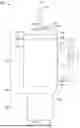
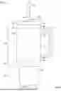


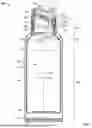
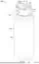
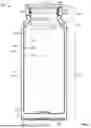
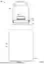


Sources:
- United States Patent and Trademark Office - verify current appl. status at the USPTO↗
Similar patent applications:
- » 10238963
Stock material for container body of insulating paper container, insulating paper container and process for making them - » 20080197139
Temperature controlled shipping using one or more smaller insulated containers inside a larger insulated container - » 20230166902
Insulated container and method of assembling an insulated container - » 20140263369
Insulating container and methods of making an insulating container - » 20170276286
Heat-insulating container provided with vacuum heat-insulating material, vacuum heat-insulating material, and tanker provided with heat-insulating container - » 20160060016
Apparatus having rigid thermally-insulated container, table assembly and collapsible thermally-insulated container - » 19188608
Insulated container and method of forming and loading an insulated container - » 18754672
Insulated container and method of forming and loading an insulated container - » 20220204245
Insulated container and method of forming and loading an insulated container - » 20230399163
Insulated container and method of forming and loading an insulated container
Recent applications in this class:
- » 20260035135 2026-02-05
SOUND ATTENUATION FOR MATERIAL HANDLING SYSTEMS - » 20260008592 2026-01-08
MODIFIED ATMOSPHERE PACKAGING CONTAINER AND METHOD FOR ATTACHING MULTI-LAYERED PEELABLE LINER TO MOLDED FIBER STRUCTURE - » 20250388365 2025-12-25
LINER FOR FREEZE DRYING TRAY - » 20250368394 2025-12-04
ALUMINUM PACKAGING CONTAINER, PACKAGED PRODUCT AND METHOD - » 20250153902 2025-05-15
DRINKING CUPS MADE FROM CARDBOARD COATED WITH PRINTING LAYER AND CROSSLINKED POLYSILOXANE LAYER - » 20250128858 2025-04-24
CONTAINER LINER - » 20250042614 2025-02-06
CLOSED-HEAD DRUM WITH LINER, AND METHOD FOR PRODUCING THE SAME - » 20250033832 2025-01-30
METALLIC BEVERAGE CONTAINERS WITH CORROSION INHIBITORS AND METHODS OF MANUFACTURING THE SAME - » 20240417138 2024-12-19
PASSIVATION, pH PROTECTIVE OR LUBRICITY COATING FOR PHARMACEUTICAL PACKAGE, COATING PROCESS AND APPARATUS - » 20240351746 2024-10-24
COMPOSITIONS FOR CONTAINERS AND OTHER ARTICLES AND METHODS OF USING SAME