COLLAPSIBLE INTERMODAL CONTAINER
US20260054918A1
2026-02-26
18/860,577
2023-04-28
Smart Summary: A collapsible intermodal container is designed to be easily folded and stored when not in use. It has a skeleton structure that provides support and can be assembled quickly. The container includes separate parts for the walls, roof, and floor, making it flexible and efficient. This design helps save space during transportation and storage. Overall, it aims to improve the way containers are used in shipping and logistics. 🚀 TL;DR
Abstract:
The present invention is broadly directed to a collapsible intermodal container. The invention is also generally directed to a skeleton structure assembly as well as wall, roof, and floor structure sub-assemblies.
Applicant:
Interested in similar patents?
Get notified when new applications in this technology area are published.
Classification:
B65D88/522 » CPC main
Large containers collapsible, i.e. with walls hinged together or detachably connected all side walls hingedly connected to each other or to another component of the container
B65D88/52 IPC
Large containers collapsible, i.e. with walls hinged together or detachably connected
Description
RELATED APPLICATIONS
This is a national stage under 35 U.S.C. § 371 of International Application No. PCT/AU2023/050354, filed Apr. 28, 2023, which claims convention priority from Australian Provisional Patent Application No. 2022901112 and Australian Provisional Patent Application No. 2022901637, the contents of which are incorporated herein in their entirety by reference thereto.
TECHNICAL FIELD
The present invention relates to a collapsible intermodal container.
BACKGROUND OF INVENTION
It is known in the prior art to construct foldable intermodal or shipping containers. The foldable container is preferably of a modular construction such as that disclosed in the applicant's International patent publication no. WO2018/145140 (WO'140). In the preferred embodiment of WO'140 the roof is hinged to an upper side of one wall, and the floor is hinged to a lower side of an opposing wall. The container of this embodiment includes link members at one end pivotally connected to the roof or the floor, and at an opposite end pivotally connected to an associated of the opposing walls. The hinged connection of the roof to the wall and the floor to the other wall is in the form of a piano-style hinge which together with the link members cooperate to facilitate collapsing and expansion of the foldable container. Foldable containers of this and similar constructions suffer from reliability issues including their failure in collapsing and/or expanding.
It is to be understood that any acknowledgement of prior art in this patent specification is not to be taken as an admission that this prior art is common general knowledge in Australia or elsewhere.
It is an object of at least a preferred embodiment of the present invention to provide an alternative to existing foldable or collapsible containers.
SUMMARY OF INVENTION
There is disclosed, in a first aspect, a collapsible intermodal container comprising:
-
- opposing first and second elongate side walls each having lower and upper opposing sides;
- an elongate floor having opposing sides and being connected to the first side wall;
- an elongate roof having opposing sides and being connected to the second side wall;
- wherein the container is configured for movement between (a) an expanded configuration where the opposing side walls are disposed parallel to and separated from one another to define a space for storing goods, and (b) a collapsed configuration where the opposing side walls approach one another remaining parallel to one another;
- wherein the first and second side wall include a first and second wall skeleton frameworks respectively, each of said wall skeleton frameworks including a wall perimeter frame and a plurality of longitudinally spaced and transversely oriented wall members, each of said wall members being connected at opposing ends to respective opposing sides of the wall perimeter frame; and
- wherein the roof includes a roof skeleton framework, said roof skeleton framework including a roof perimeter frame and a plurality of longitudinally spaced and transversely oriented roof beams, said wall skeleton frameworks and the roof skeleton framework cooperating with one another for stiffening of the collapsible intermodal container.
Preferably, the opposing first and second elongate side walls remain substantially parallel to one another whilst the collapsible container is moved between the expanded configuration and the collapsed configuration.
Preferably, one of the sides of the elongate floor is connected to the lower side of the first side wall, and
-
- wherein one of the sides of the elongate roof is connected to the upper side of the second side wall.
Preferably, said wall and roof skeleton frameworks provide stiffening of said container in the expanded and collapsed configurations as well as stiffening of said container in any intermediate configuration between the expanded and collapsed configurations.
Preferably, the wall and roof skeleton frameworks each remain substantially whole and unmodified between in the intermediate configurations.
Preferably, the plurality of longitudinally spaced roof beams substantially align with corresponding of the plurality of longitudinally spaced wall members of both the first and second wall skeleton frameworks.
Preferably, the plurality of longitudinally spaced wall members include multiple pairs of said wall members.
Preferably, each of the plurality of roof beams substantially aligns with a corresponding one of the multiple pairs of the wall members together forming one of a plurality of longitudinally spaced ring frames enhancing the structural rigidity of the collapsible intermodal container.
Preferably, the container further includes a plurality of floor hinges connected to said one of the opposing sides of the floor and the lower of the opposing sides of the first wall to permit hinging between the floor and the first wall, and a plurality of roof hinges connected to said one of the opposing sides of the roof and the upper of the opposing sides of the second wall to permit hinging between the roof and the second wall.
Preferably, the plurality of floor hinges include multiple pairs of said hinges, each of said pairs of hinges being in substantial alignment with corresponding of one of the multiple pairs of the wall members of the first wall.
Preferably, the plurality of roof hinges include multiple pairs of said hinges, adjacent of said pairs of hinges being equally spaced in substantial alignment with corresponding of one of the multiple pairs of the wall members of the second wall.
Preferably, the floor/roof hinge includes a hinge member having a first extension connected to either the floor or the roof and a second extension hingedly coupled to the first or the second side wall via a hinge pin mounted to said wall adjacent its lower or upper sides, said first and second extensions being formed perpendicular to one another to provide eccentric movement of the floor or roof relative to its corresponding side wall during movement of the collapsible container between its expanded and collapsed configurations.
Preferably, the hinge pin is separated a distance from the lower or upper side of the corresponding wall thereby enabling the eccentric movement of the floor or roof.
Preferably, the container further includes a plurality of first track members associated with the first of the opposing pair of walls, each of said first track members configured to be inter-engaged by one of a plurality of corresponding roof carriages connected to the roof, whereby movement of said collapsible container between the expanded and the collapsed configurations is accompanied by sliding movement of the roof carriages relative to the corresponding first track members.
Preferably, the plurality of first track members are mounted to the first wall between respective of the multiple pairs of wall members of the first wall skeleton.
Preferably, also comprising a plurality of second track members associated with the second wall, each of said second track members configured to be inter-engaged by one of a plurality of corresponding floor carriages connected to the floor whereby movement of said collapsible container between the expanded and the collapsed configurations is accompanied by sliding movement of the floor carriages relative to the corresponding second track members.
Preferably, the plurality of second track members are mounted to the second wall between respective of the multiple pairs of wall members of the second wall skeleton.
Preferably, each of the track members are welded or otherwise attached to the corresponding pair of wall members.
Preferably, the roof perimeter frame is elongate and adapted for connection to a roof panel associated with the roof; and
-
- the plurality of longitudinally spaced and transversely oriented roof beams is connected to respective of opposing sides of the roof perimeter frame thereby stiffening the roof panel.
Preferably, the roof panel includes a plurality of perimeter sides, and the roof perimeter frame is in alignment with the roof panel at or adjacent the perimeter sides.
Preferably, the floor includes a floor skeleton framework, said floor framework comprising:
-
- a floor perimeter frame being elongate and adapted for connection to one or more floor panels associated with the floor;
- a plurality of longitudinally spaced and transversely oriented floor beams, each of said transverse beams at opposing ends connected to respective of opposing longitudinal beams of the floor perimeter frame thereby stiffening the floor;
- a pair of support beams connected at opposing ends to respective of the opposing longitudinal beams, said support beams (a) disposed parallel to the transverse floor beams and (b) longitudinally separated by a predetermined distance.
Preferably, the opposing longitudinal beams of the floor perimeter frame each include a plate recess adapted to receive a transition plate connected to a lower of the opposing longitudinal beams of the perimeter frame of each of the opposing side walls, said transition plates being arranged, in the expanded configuration of the collapsible container, to bridge the longitudinal beams of the floor perimeter frame and respective of the lower longitudinal beams of the wall perimeter frames such that the container, when expanded, is continuously supported when being moved on a roller track.
Preferably, the plate recesses of respective of the opposing longitudinal beams of the floor perimeter frame and the corresponding transition plates of the opposing side walls are longitudinally offset from one another thereby enabling receipt of said transition plates within plate recesses of the lower longitudinal beams of the opposing side walls during movement of the collapsible container into the collapsed configuration whereupon the transition plates bridge said lower beams of the side walls, such that the container, when collapsed, is continuously supported when being moved in the on a roller track.
Preferably, the wall perimeter frame is elongate and adapted for connection to a wall panel associated with one of the pair of side walls; and
-
- wherein the wall frameworks each include a plurality of longitudinally spaced and transversely oriented wall members, each of said wall members at opposing ends connected to respective of opposing sides of the wall perimeter frame thereby stiffening the wall panel.
Preferably, the wall panel includes a plurality of perimeter sides, and the wall perimeter frame is connected to and in alignment with the wall panel at or adjacent its perimeter sides.
There is disclosed, in a second aspect, a collapsible intermodal container including a pair of opposing side walls each hingedly connected to respective of a roof and a floor wherein said walls remain substantially parallel to one another whilst the collapsible container is moved between an expanded configuration and a collapsed configuration, the container including a carriage and track sub-assembly of said sub-assembly comprising:
-
- one or more spaced track members adapted for connection to a wall skeleton framework associated with one of the pair of opposing side walls; and one or more of:
- a roof carriage adapted to connect to a roof skeleton framework associated with the roof, the roof carriage configured to inter-engage said one of the track members for sliding movement of said carriage relative to said track member during movement of the collapsible container between the expanded and the collapsed configurations;
- a floor carriage adapted to connect to a floor skeleton framework associated with the floor, the floor carriage configured to inter-engage said one of the track members for sliding movement of said carriage relative to said track member during movement of the collapsible container between the expanded and collapsed configurations.
- one or more spaced track members adapted for connection to a wall skeleton framework associated with one of the pair of opposing side walls; and one or more of:
Preferably, the carriage includes a slidable car having a plurality of rollers configured for sliding movement along track member.
Preferably, the carriage includes a carriage mounting bracket for rigid connection to the roof or the floor, and a coupling arm pivotally coupled at its opposing ends to the mounting bracket and the slidable car, respectively.
Preferably, the coupling arm includes a recess facing away from the side wall, and the slidable car includes a limit bar facing toward the side wall, the recess and the limit bar being located such that the pivoting of the coupling arm relative to the slidable car is limited by the limit bar.
Preferably, the carriage mounting bracket is detachably mounted to a perimeter frame of the roof or a side rail of the floor via one or more carriage mounting fasteners.
Preferably, the slidable car includes a car body to which the rollers are rotatably mounted about an axis of rotation perpendicular to the corresponding wall.
Preferably, the slidable car includes a car body to which the rollers are rotatably mounted about an axis of rotation parallel to an elongate axis of the side wall.
Preferably, the car body includes a stop member protruding from the car body to limit movement of the car body within the track member when the container has been moved to the collapsed configuration.
Preferably, the track members are in cross-section of a generally C-shaped profile and configured for captive retention of the plurality of rollers, such that the rollers together with the corresponding track member cooperate to handle both axial and radial loads imposed on said rollers during movement of the intermodal container between its expanded and collapsed configurations.
Preferably, the C-shaped profile track members are each attached to an opposing pair of wall members of the wall skeleton framework.
Preferably, attachment of the track member to the opposing wall members is provided at an exposed and inward facing junction between the wall members and the track member thereby stiffening the track member along its opposing edge portions bounding a slot opening of the C-shaped profile.
Preferably, each of the track members is fabricated from one or more plates connected at opposing edges to one or more of a pair of opposing channel-section members together forming the C-shaped profile track member.
There is disclosed herein, in a third aspect, a collapsible intermodal container including a pair of opposing side walls each hingedly connected to respective of a roof and a floor wherein said opposing walls remain parallel to one another whilst the container is moved between an expanded configuration, wherein the side walls, the roof, and the floor define a space for storing goods, and a collapsed configuration, the collapsible intermodal container including an end frame and door assembly for sealing the space in the expanded configuration, said end frame and door assembly including:
-
- an end frame extending perpendicular to the pair of opposing side walls and adapted to releasably engage at least one of the side walls, roof and floor of said container thereby retaining it in the expanded configuration;
- a pair of doors hingedly connected to respective opposing sides of the end frame, said doors being movable from a closed position to an open position for access to the space within the collapsible container in the expanded configuration;
- a pair of stabilising members connected to the respective pair of doors, the stabilizing member being connected to the doors proximal upper or lower adjacent corners of said doors, said stabilising members being configured, when the doors are in the closed position, to engage an anchor member associated with correspondingly either upper or lower beams of the end frame, thereby stabilising the container in its expanded configuration and under transverse loading.
Preferably, the stabilising members include a hook member configured with the doors in the closed position to hook either side of the anchor member located centrally of the upper or lower beams of the end frame.
Preferably, the anchor member includes a profile shape at least in part shaped complementary to a corresponding and profiled edge face of the hook member.
Preferably, each of the doors is hingedly connected to the end frame via three door hinges.
Preferably, the pair of stabilising members include upper and lower pairs of stabilising members arranged to cooperate with upper and lower anchor members respectively of the end frame.
There is disclosed herein, in a fourth aspect, a collapsible intermodal container including a pair of opposing side walls each hingedly connected to respective of a roof and a floor wherein said opposing walls remain parallel to one another whilst the collapsible container is moved between an expanded configuration, wherein the side walls, the floor, the roof, and a capping end frame define a space for storing goods, and a collapsed configuration, wherein the end frame has completed a hinged movement about one of the pair of opposing side walls between (i) a closed position extending perpendicular to the pair of said walls, and (ii) an open position extending parallel to, and disposed on an outer face of, said one of the walls, the collapsible intermodal container including an end frame locking assembly for securing the end frame to the side wall in the collapsed configuration, said locking assembly comprising:
-
- a retractable pin sub-assembly including a retractable pin, said pin sub-assembly adapted to mount to an end frame of said collapsible container; and
- a receiver sub-assembly adapted to mount to said one of the side walls, the receiver sub-assembly including a locking member configured with the end frame in the open position to receive the retractable pin in an extended position whereby said extended pin is releasably engaged by the locking member to retain the end frame in the open position.
Preferably, the retractable pin includes an engaging end having a slot for releasable engagement by the locking member of the receiver sub-assembly with the retractable pin in the extended position thereby retaining the end frame.
Preferably, the retractable pin sub-assembly includes pin biasing means arranged to cooperate with radial protrusions connected to the retractable pin, said biasing means arranged to retract the retractable pin toward a retracted position displaced from the extended position and out of engagement with the locking member of the received sub-assembly.
Preferably, the retractable pin includes an actuating end located at an opposite end to the engaging end, said actuating end adapted for pressing for displacement of the retractable pin from the retracted position against the force of the biasing means toward the extended position.
Preferably, the retractable pin sub-assembly includes a retractable pin casing arranged for housing the biasing means and the radial protrusions of the retractable pin, said casing having an opposing pair of openings through which the respective engaging end extends and the actuating end is exposed.
Preferably, the retractable pin sub-assembly includes pin biasing means arranged to cooperate with an actuating element connected to an opposing end of the retractable pin distal from the engaging end, said biasing means arranged to retract the retractable pin toward a retracted position displaced from the extended position and out of engagement with the locking member of the receiver sub-assembly.
Preferably, the actuating element includes an actuating surface adapted for pressing for displacement of the retractable pin from the retracted position against the force of the biasing means toward the extended position.
Preferably, the retractable pin sub-assembly includes a retractable pin casing arranged for housing the biasing means in the form of a spring mounted about the retractable pin, said casing having an opposing pair of openings through which the respective engaging end extends and the actuating surface is exposed.
Preferably, the retractable pin at its engaging end includes a shoulder arranged to abut the casing and thus limit travel of the retractable pin under the influence of the pin biasing means towards the retracted position.
Preferably, the retractable pin casing is adapted for mounting within an upper beam of the end frame of said collapsible container.
Preferably, the receiver member includes a receiver casing housing the locking member which cooperates with lock biasing means which urges said locking member into an engaged position where it releasably engages the retractable pin in the extended position.
Preferably, the locking member includes a locking plate having a latch element for releasable engagement with the slot of the engaging end of the retractable pin in its extended position, said latching element being retained in a latched position under the influence of the lock biasing means which urges the locking member into the engaged position.
Preferably, the locking member includes a locking rod for releasable engagement with the slot of the engaging end of the retractable pin in its extended position, said locking rod being retained in a latched position under the influence of the lock biasing means which urges the locking member into the engaged position.
Preferably, the latch element or the locking rod is arranged to cooperate with the engaging end of the retractable pin which during displacement toward the extended position contacts the latch element or the locking rod moving the locking member toward an unlatched position permitting further displacement of the retractable pin into the extended position whereupon the latch element or the locking rod under the influence of the lock biasing means latches the slot of the retractable pin.
Preferably, the engaging end of the retractable pin is tapered for sliding contact with a ramped surface of the latch element or the locking rod during displacement of the retractable pin toward its extended position thereby urging the locking member against the force of the lock biasing means into a disengaged position.
Preferably, the locking member includes a lock actuator associated with the locking plate or the locking rod, said lock actuator with the latching element or the locking rod in the latched position being arranged for movement via an external lock actuator for displacement of the locking member and the associated latch element or the locking rod against the force of the lock biasing means thereby releasing the retractable pin for retraction from its extended position.
Preferably, the receiver casing is adapted for mounting within an upper beam of said one of the pair of opposing side walls of the collapsible container.
There is disclosed herein, in a fifth aspect, a collapsible intermodal container including a pair of opposing side walls each hingedly connected to respective of a roof and a floor wherein said opposing walls remain parallel to one another whilst the collapsible container is moved between an expanded configuration, wherein the side walls, the floor, the roof, and a capping end frame define a space for storing goods, and a collapsed configuration, wherein the end frame has completed a hinged movement about one of the pair of opposing side walls between (i) a closed position extending perpendicular to the pair of said walls, and (ii) an open position extending parallel to, and disposed on an outer face of, said one of the walls, the container including a locking assembly for locking the end frame to the roof or floor when the container is in the expanded configuration, said locking assembly comprising:
-
- a stud sub-assembly adapted to mount to the roof or the floor, said stud sub-assembly including a pull stud;
- a receiver sub-assembly adapted to mount to the end frame, the receiver sub-assembly including a locking member operatively coupled to a receiver member arranged with the collapsible container in the expanded configuration and the end frame in the closed position to receive the pull stud which is releasably engaged by the locking member to releasably lock the end frame in the closed position to the roof or the floor thereby retaining the collapsible container in the expanded configuration.
Preferably, the pull stud is adapted to be rigidly fixed to a front or a rear beam of the roof or the floor of the collapsible container, the pull stud including an engaging end having a groove for releasable engagement with the locking member of the receiver sub-assembly thereby retaining the end frame in the closed position.
Preferably, the receiver member includes a receiver housing being configured to retractably receive the pull stud, the locking member arranged to cooperate with lock biasing means which urges said locking member into an engaged position where it releasably engages the groove of the pull stud.
Preferably, the locking member is one of a pair of locking members arranged in the engaged position to latch within the groove of the pull stud.
Preferably, the pair of locking members are in the form of a pair of locking posts disposed either side of the pull stud when received within the receiver housing, the locking posts arranged for sliding movement in a reciprocating action relative to the receiver housing and under the influence of the lock biasing means being urged toward the engaged position of the locking member.
Preferably, the locking posts are operatively coupled to a lock actuator wherein the lock biasing means is located between the receiver housing and the lock actuator thereby urging the locking member and its locking posts into the engaged position via the lock actuator.
Preferably, the pair of locking posts are fastened to the lock actuator via an associated pair of slide lock shafts slidably received in a corresponding pair of shaft passages formed within the receiver housing thereby enabling movement of the locking posts in the reciprocating action.
Preferably, the locking member includes a rebate at least in part profile being shaped complementary to a corresponding profile of the groove of the pull stud, said locking member thus configured in the engaged position to latch within the groove of the pull stud.
Preferably, the locking member is arranged for sliding movement in a reciprocating action relative to the receiver housing and under the influence of the lock biasing means being urged toward the engaged position of the locking member.
Preferably, the locking member is operatively coupled to a lock actuator wherein the biasing means is located between the receiver housing and the lock actuator thereby urging the locking member into the engaged position via the lock actuator.
Preferably, the locking member is fastened to the lock actuator via an associated pair of side lock shafts slidably received in a corresponding pair of shaft passages formed within the receiver housing thereby enabling movement of the locking member in the reciprocating action.
Preferably, the engaging end of the pull stud is tapered for sliding contact with a ramped surface of each of the pair of locking posts or the rebate of the locking member so that, during movement of the pull stud into the receiver housing and into releasably engagement with the locking member, the locking member is urged against the force of the lock biasing means toward the disengaged position for continued movement of the pull stud into the receiver housing in anticipation of its engagement with the locking member in the engaged position.
Preferably, the receiver housing is adapted for mounting within an upper or lower beam of the end frame of the collapsible container.
There is disclosed herein, in a sixth aspect, a collapsible intermodal container including a pair of opposing side walls each hingedly connected to respective of a roof and a floor wherein said opposing walls remain parallel to one another whilst the collapsible container is moved between an expanded configuration, wherein the side walls, the floor, the roof, and a capping end frame define a space for storing goods, and a collapsed configuration, wherein the end frame has completed a hinged movement about one of the pair of opposing side walls between (i) a closed position extending perpendicular to the pair of said walls, and (ii) an open position extending parallel to, and disposed on an outer face of, said one of the walls, the container including a locking assembly for locking the end frame to the first and/or the second side wall, said locking assembly comprising;
-
- a stud sub-assembly adapted to mount to at least one of the pair of side walls, said stud sub-assembly including a pull stud;
- a receiver sub-assembly adapted to mount to the end frame, the receiver sub-assembly including a locking member operatively coupled to a receiver member arranged with the collapsible container in the expanded configuration and the end frame in the closed position to receive the pull stud which is releasably engaged by the locking member to releasably lock the end frame in the closed position to said at least one of the side walls thereby retaining the collapsible container in the expanded configuration.
Preferably, the pull stud is adapted to be rigidly fixed to a front or rear member of the side wall of the collapsible container, the pull stud including an engaging end having a groove for releasable engagement with the locking member of the receiver sub-assembly thereby retaining the end frame in the closed position.
Preferably, the receiver member includes a receiver housing, the locking member arranged to cooperate with lock biasing means which urges said locking member into an engaged position where it releasably engages the groove of the pull stud.
Preferably, the locking member is one of a pair of locking members arranged in the engaged position to latch within the groove of the pull stud.
Preferably, the pair of locking members are in the form of a pair of locking posts disposed either side of the pull stud when received within the receiver housing, the locking posts arranged for sliding movement in a reciprocating action relative to the receiver housing and under the influence of the lock biasing means being urged toward the engaged position of the locking member.
Preferably, the locking posts are operatively coupled to a lock actuator wherein the lock biasing means is located between the receiver housing and the lock actuator thereby urging the locking member and its locking posts into the engaged position via the lock actuator.
Preferably, the pair of locking posts are fastened to the lock actuator via an associated pair of slide lock shafts slidably received in a corresponding pair of shaft passages formed within the receiver housing thereby enabling movement of the locking posts in the reciprocating action.
Preferably, the locking member includes a rebate at least in part profile being shaped complementary to a corresponding profile of the groove of the pull stud, said locking member thus configured in the engaged position to latch within the groove of the pull stud.
Preferably, the locking member is arranged for sliding movement in a reciprocating action relative to the receiver housing and under the influence of the lock biasing means being urged toward the engaged position of the locking member.
Preferably, the locking member is operatively coupled to a lock actuator wherein the biasing means is located between the receiver housing and the lock actuator thereby urging the locking member into the engaged position via the lock actuator.
Preferably, the locking member is fastened to the lock actuator via an associated pair of side lock shafts slidably received in a corresponding pair of shaft passages formed within the receiver housing thereby enabling movement of the locking member in the reciprocating action.
Preferably, the engaging end of the pull stud is tapered for sliding contact with a ramped surface of each of the pair of locking posts or the rebate of the locking member so that, during movement of the pull stud into the receiver housing and into releasably engagement with the locking member, the locking member is urged against the force of the lock biasing means toward the disengaged position for continued movement of the pull stud into the receiver housing in anticipation of its engagement with the locking member in the engaged position.
Preferably, the receiver housing is adapted for mounting within an upper or lower beam of the end frame of the collapsible container.
Preferably, each locking assembly further includes:
-
- a second stud sub-assembly adapted to mount to one of the opposing pair of side walls, said stud sub-assembly including a second pull stud; and
- wherein the locking member is operatively coupled to a first receiver member arranged with the collapsible container in the expanded configuration and the end frame in the closed position to receive the first pull stud which is releasably engaged by the first locking member to releasably lock the end frame in the closed position to the roof or the floor thereby retaining the collapsible container in the expanded configuration, and the receiver subassembly further includes:
- a second locking member operatively coupled to a second receiver member arranged with the collapsible container in the expanded configuration and the end frame in the closed position to receive the second pull stud which is releasably engaged by the second locking member to releasably lock the end frame in the closed position to said one of the opposing walls thereby retaining the collapsible container in the expanded configuration.
Preferably, the locking assembly further includes a receiver casing configured to contain the first and the second locking and receiver members.
Preferably, the receiver casing includes an opening exposing an actuator button arranged on pressing via an external lock actuator to interact with the lock actuators for movement of the respective first and second locking members against the force of the lock biasing means toward the disengaged position for release of the first and second pull studs from the respective first and second receiver members.
Preferably, the first and second receiver members are integral with one another forming a receiver casing, and the lock actuator is common to both the first and second locking members.
Preferably, the receiver casing includes an opening exposing the common lock actuator arranged on pressing via an external lock actuator to effect movement of the first and second locking members against the force of the lock biasing means toward the disengaged position for release of the first and second pull studs from the respective first and second receiver members.
Preferably, the pull studs cooperating with the first and second receiver members associated with the lower beam of the end frame of the collapsible container are of a shorter relative length.
Preferably, the shorter length pull studs include the groove being of a relatively large diameter and width.
Preferably, the receiver casing is adapted for mounting within an upper or lower beam of the end frame of the collapsible container.
There is disclosed herein, in a seventh aspect, a collapsible intermodal container including a pair of opposing side walls each hingedly connected to respective of a roof and a floor wherein said opposing walls remain parallel to one another whilst the collapsible container is moved between an expanded configuration and a collapsed configuration, the container including a locking assembly for securing the side wall to the floor and/or roof, said locking assembly comprising:
-
- a retractable plunger sub-assembly adapted to mount to at least one of the pair of side walls, said plunger sub-assembly including (a) a retractable plunger configured to move between an extended position and a retracted position, and (b) a locking member arranged to cooperate with the plunger to lock it in the extended position;
- a receiver sub-assembly adapted to mount to either the floor or the roof, the receiver sub-assembly including a catch member configured with the collapsible container in the expanded configuration to receive the retractable plunger in the extended position whereby said plunger is locked via the locking member to releasably retain the floor or the roof relative to the corresponding of the pair of opposing walls thereby retaining the collapsible container in the expanded configuration.
Preferably, the plunger sub-assembly also includes a plunger casing housing the retractable plunger and the cooperating locking member, the plunger casing adapted for mounting at least partly within a lower or upper beam of said one of pair of walls.
Preferably, the plunger sub-assembly also includes plunger biasing means mounted within the plunger casing and arranged to act on the retractable plunger to urge it toward the retracted position.
Preferably, the plunger sub-assembly also includes lock biasing means arranged to cooperate with the locking member or urge it into a locked disposition to retain the plunger in the extended position.
Preferably, the retractable plunger includes a pair of grooves arranged in the extended position of said plunger to be engaged by a corresponding pair of posts of the locking member which is urged via the lock biasing means into the locked disposition to retain the plunger in the extended position.
Preferably, the pair of posts each include a rebate configured with the locking member in an unlocked disposition to permit sliding movement of the retractable plunger from the retracted to the extended positions and vice versa, the rebates of the posts guiding the plunger in its sliding movement between the posts.
Preferably, the retractable plunger includes a radial protrusion configured to be releasably engaged by the locking member in the locked disposition.
Preferably, the locking member includes a frame member having a ledge configured for releasable engagement with the protrusion of the plunger to retain it in the extended position.
Preferably, the locking member includes a locking actuator exposed via a locking actuator opening in the plunger casing, the locking actuator being depressed via an external lock actuator to effect movement of the locking member to the unlocked disposition against the force of the lock biasing means thereby permitting sliding movement of the plunger from its retracted to the extended positions against the force of the plunger biasing means.
Preferably, the retractable plunger includes a plunger actuator exposed via a plunger actuator opening in the plunger casing, the plunger actuator being depressed via an external plunger actuator for sliding movement of the plunger from its retracted to the extended positions.
Preferably, the container further includes:
-
- a plurality of spigots mounted to at least one of the pair of side walls, said spigots being longitudinally spaced along said one of the side walls;
- a plurality of receivers mounted to either the roof or the floor, said receivers being longitudinally spaced along the roof or the floor in substantial alignment with the plurality of spigots whereby with the collapsible container in the expanded configuration each of the plurality of receivers is arranged to receive respective of the plurality of spigots thereby aligning the roof or the floor of said container with the associated side wall.
Preferably, each of the plurality of spigots is in the form of a cone-shaped stud adapted to mount to an upper or a lower beam of said one of the pair of side walls.
Preferably, each of the plurality of receivers is in the form of a cone-shaped cup having a cavity shaped substantially complementary to a corresponding of the cone-shaped studs, said cone-shaped cups adapted to mount to a lower or upper beam of the floor or the roof, respectively.
Preferably, the plurality of spigots and receivers are arranged in pairs wherein neighbouring of said pairs are substantially equally spaced longitudinally along said wall and either the roof or the floor.
Preferably, the container further includes:
-
- one or more wedge-shaped members mounted to either or both of the roof or the floor opposite its hinged connection to the respective side wall;
- one or more receivers adapted to mount to either of the opposing side walls, each of said receivers located for alignment with a corresponding of each of said wedge-shaped members which on movement of the collapsible container into the expanded configuration are received within the aligned receivers for alignment of the roof or the floor of said container with the associated wall.
Preferably, the wedge-shaped members are mounted to both the roof and the floor, and the receivers are mounted to upper and lower longitudinal beams of respective of the opposing side walls.
Preferably, each of the receivers is in the form of a channel oriented parallel to the upper or lower beam of the side wall with which it is associated, said channel at least in part being wedge-shaped and of a complementary sectional shape to corresponding of the wedge-shaped members.
There is disclosed herein, in an eighth aspect, a collapsible intermodal container including a pair of opposing side walls, each side wall being hingedly connected to a roof and a floor respectively, wherein said opposing walls remain parallel to one another whilst the collapsible container is moved between an expanded configuration, wherein the roof and the floor extend substantially perpendicularly between the side walls, and a collapsed configuration, wherein the roof and the floor extend substantially parallel to the side walls, the container including a locking assembly for securing the roof or the floor in the expanded configuration, the locking assembly including:
-
- a rotatable shaft having a drive head that is driveable by an actuator;
- a locking member moved by the shaft between a free position and a locking position, wherein, in the locking position, the locking member engages the roof or the floor to resist movement of the roof or the floor in a vertical direction and thereby retain the roof or the floor in the expanded configuration.
Preferably, the locking member includes a hook portion that engages a recess in the roof or the floor when the locking member is in the locking position, to prevent rotation of the shaft beyond the locking position and resist movement of the roof or the floor in a direction parallel to an elongate direction of the side wall and/or a direction normal to the side wall.
Preferably, the locking assembly is for securing the roof in the expanded configuration, and wherein the locking member includes a taper in a direction of movement of the locking member, such that when the locking member moves from the free position to the locking position, the roof is urged upwards into the collapsed configuration.
Preferably, the taper of the locking member is dimensioned such that the roof is urged upwardly in the expanded configuration, to ensure a sealing pressure between the roof and the side wall is created.
There is disclosed herein, in a ninth aspect, a collapsible intermodal container including a pair of opposing elongate side walls, each side wall being hingedly connected to a roof and a floor respectively, with an end frame hingedly connected to one side wall to cap the opening created between the side walls, the roof, and the floor, wherein said opposing walls remain parallel to one another whilst the collapsible container is moved between an expanded configuration, wherein the roof and the floor extend substantially perpendicularly between the side walls, and a collapsed configuration, wherein the roof and the floor extend substantially parallel to the side walls, wherein the end frame is hingedly moveable about one of the pair of opposing side walls between (i) a closed position extending perpendicular to the pair of said walls, and (ii) an open position extending parallel to, and disposed on an outer face of, said one of the walls,
-
- the container including a locking assembly for securing the end frame to the outer face of the side wall, the locking assembly including:
- a rotatable shaft having a drive head that is driveable by an actuator;
- a locking member moved by the shaft between a free position and a locking position, wherein, in the locking position, the locking member engages the end frame to resist movement of the end frame relative to the side wall and thereby retain the end frame in the open position.
Preferably, end frame includes a corner casting having a twist lock aperture, and
-
- wherein the locking member includes a hook portion dimensioned to hook into the twist lock aperture and engage an interior surface of the corner casting to retain the end frame in the open position.
Preferably, the hook portion has a height sufficient such that an upper surface of the hook portion engages an inside surface of the top of the twist lock aperture, such that sagging of the end frame is resisted by the hook portion.
Preferably, the locking assembly is housed in the side wall, and wherein the locking member protrudes from the side wall in the locking position and is received entirely within the side wall in the free position.
Preferably, the end frame includes a corner casting, the corner casting having a front face, a rear face, a side face, and a vertical face, the corner casting including:
-
- a first standard aperture in the front face;
- a second standard aperture in the side face;
- a third standard aperture in the vertical face; and
- a fourth aperture in the rear face.
Preferably, the corner casting has a length from the front face to the rear face that exceeds 185 mm.
Preferably, the locking assembly is located in the side wall facing in the elongate direction of the side wall, and wherein the locking member includes a twist lock member is asymmetric about an axis of the rotatable shaft and moveable between the free position, wherein the twist lock member is able to move through the fourth aperture, and the locking position, wherein the twist lock member, when inserted through the fourth aperture into the corner casting, engages an internal surface of the corner casting for securing the end frame in the closed position.
There is disclosed herein, in a tenth aspect, a collapsible intermodal container including a pair of opposing side walls, each side wall being hingedly connected to a roof and a floor respectively, wherein said opposing walls remain parallel to one another whilst the collapsible container is moved between an expanded configuration, wherein the roof and the floor extend substantially perpendicularly between the side walls, and a collapsed configuration, wherein the roof and the floor extend substantially parallel to the side walls, the container including a compound beam profile formed from:
-
- a first beam portion having a first beam profile including:
- a first portion having a first height;
- a second portion extending from the first portion and having a common base profile with the first portion and a second height, the second height being lower than the first height, the second portion having a planar contact surface ending in an upwardly extending lip;
- a second beam portion having a second beam profile including:
- a first portion having a first height;
- a second portion extending from the first portion and having a common top profile with the first portion and a second height, the second height being lower than the first height, the second portion having a planar contact surface ending in a downwardly extending lip;
- a sealing member extending between first beam and the second beam,
- wherein, when the first beam portion is arranged with the second beam portion, the second portions engage such that lip of each beam contacts the planar contact surface of the other beam.
- a first beam portion having a first beam profile including:
Preferably, the contact surfaces are arranged such that, when the first beam portion is arranged with the second beam portion and a vertical load is applied to the compound beam, the engagement of the lips urges the beams towards each other, exerting a compressive force on the sealing member between the beams.
Preferably, the sealing material includes a seal located between the first portion of one of the beams and the second portion of the other beam.
Preferably, the second portion of the first and/or the second beam includes a reinforcing member, such that a vertical load applied to the compound beam forms a load path through the reinforcing member.
Preferably, the reinforcing member is U shaped.
BRIEF DESCRIPTION OF DRAWINGS
A preferred embodiment of a collapsible intermodal container will now be described, by way of example only, with reference to the accompanying drawings in which:
FIG. 1A is an isometric view of a collapsible intermodal container of a preferred embodiment of first to fourth aspects of the invention shown in its expanded configuration;
FIGS. 1B and 1C are isometric and detailed view of the collapsible intermodal container of the preferred embodiment of FIG. 1 shown for clarity purposes in an inverted position;
FIG. 2A is an isometric view of a collapsible intermodal container of a preferred embodiment of fifth to eighth aspects of the invention as shown in its expanded configuration;
FIGS. 2B and 2C are isometric and detailed views of a floor skeleton framework taken from the skeleton structure assembly of the preferred embodiment of FIG. 2A;
FIG. 3 is an isometric view of the collapsible intermodal container of the preferred embodiment of FIG. 1 shown in its partly collapsed configuration;
FIG. 4A is an isometric view of the collapsible intermodal container of the preferred embodiment of FIG. 1 shown in its collapsed configuration;
FIGS. 4B and 4C are isometric and detailed views of the collapsible intermodal container of the preferred embodiment of FIG. 4A shown in its inverted position;
FIGS. 5A to 5C are isometric and detailed views of a pair of roof hinges taken from the collapsible intermodal container of the preferred embodiment of FIGS. 1, 3 and 4 in its respective expanded, partly collapsed and collapsed configurations;
FIGS. 5D to 5F are isometric and detailed views of alternative roof hinges suitable for the collapsible intermodal container of the preferred embodiment of FIGS. 1 to 4;
FIGS. 6A to 6C are isometric and detailed views of a floor hinge taken from the collapsible intermodal container of the preferred embodiment of FIGS. 1, 3 and 4 shown in its respective expanded, partly collapsed and collapsed configurations;
FIGS. 6D to 6F are isometric and detailed views of alternative floor hinges suitable for the collapsible intermodal container of the preferred embodiment of FIGS. 1 to 4;
FIGS. 7A and 7B are isometric and detailed views of a carriage and track sub-assembly of a preferred embodiment of a ninth aspect of the invention taken from the collapsible intermodal container of FIGS. 1 to 4 shown in its expanded and collapsed configurations;
FIGS. 8A to 8C are isometric and detailed views of a carriage and track sub-assembly of a preferred embodiment of a tenth aspect of the invention taken from the collapsible intermodal container of FIGS. 1 to 4 shown in its expanded, partly collapsed and collapsed configurations;
FIGS. 9A to 9C are sectional and detailed views of the roof and floor hinges of FIGS. 5A and 6A shown with the collapsible intermodal container in its expanded configuration;
FIGS. 10A to 10D are sectional, detailed and isometric views of the carriage and track assembly of the ninth and tenth aspects of the invention with the collapsible intermodal container in its expanded configuration;
FIGS. 11A to 11D are top part cutaway, elevational, and detailed views of one of the side walls taken from the collapsible intermodal container of the preferred embodiment of FIGS. 1, 3 and 4 depicting part of the carriage and track sub-assembly of the ninth and tenth aspects of the invention;
FIGS. 12A and 12B are sectional and enlarged views of part of the carriage and track sub-assemblies taken from the side wall of FIG. 11 of the collapsible intermodal container of the preferred embodiment of FIGS. 1, 3 and 4;
FIGS. 13A and 13B are isometric and detailed views of a track member taken from the carriage and track assembly or sub-assembly of the collapsible container of the ninth and tenth aspects of the invention;
FIG. 14 is an isometric view of the collapsible intermodal container of the preferred embodiment of FIGS. 1, 3 and 4 shown in its expanded configuration with associated end frames in their open positions;
FIGS. 15A and 15B are detailed isometric and sectional views of an end frame locking assembly of a preferred embodiment of a thirteenth aspect of the invention taken from the collapsible intermodal container of FIG. 14;
FIG. 16A to 16C are isometric and detailed views of the collapsible intermodal container of the preferred embodiment of FIG. 14 in its expanded configuration together with an front end frame and door assembly of a preferred embodiment of a twelfth aspect of the invention shown with its doors closed and one of its doors partly open;
FIGS. 17A and 17B are detailed isometric and sectional views of a retractable pin sub-assembly of the end frame locking assembly of FIG. 15 of the preferred embodiment of the thirteenth aspect of the invention;
FIGS. 18A to 18D are various isometric and sectional views of the retractable pin-assembly of the end frame locking assembly of FIG. 15 shown removed from the end frame of the collapsible intermodal container;
FIG. 19 is an exploded view of the retractable pin sub-assembly of the end frame locking assembly of the preferred embodiment shown in FIG. 18.
FIGS. 20A and 20B are detailed isometric and sectional views of a receiver sub-assembly of the end frame locking assembly associated with one of the side walls of the collapsible container of FIG. 15;
FIGS. 21A and 21B are isometric and sectional views of the receiver sub-assembly of FIGS. 20A and 20B shown removed from the associated side wall of the collapsible intermodal container;
FIGS. 22A to 22E are isometric, exploded and sectional views of both the receiver sub-assembly of the end frame locking assembly of the preferred embodiment of FIG. 21 together with an alternative embodiment of the receiver sub-assembly;
FIG. 23A to 23C are sectional views of an end frame in its closed position relative to the associated collapsible intermodal container in its expanded configuration, the collapsible intermodal container constructed in accordance with the preferred embodiment and including (i) an end frame to roof or floor locking assembly of a fourteenth aspect of the invention, (ii) an end frame to side wall locking assembly of a fifteenth aspect of the invention, and (iii) a combined locking assembly of a sixteenth aspect of the invention;
FIGS. 24A to 24C are sectional views of a roof/floor to end frame stud and receiver assembly of a seventeenth aspect of the invention, said stud and receiver assembly associated with a roof/floor and end frame of the collapsible intermodal container of the preferred embodiment shown in its expanded configuration with the end fame in the closed position;
FIGS. 25A to 25D are sectional views of a roof/floor to end frame stud and receiver assembly of the seventeenth aspect of the invention, said stud and receiver assembly associated with a roof/floor and end frame of the collapsible container of the preferred embodiment shown in its collapsed configuration with the end frame in the closed position to cooperate with stud sub-assemblies of a further collapsible container in the collapsed configuration;
FIG. 26 is an isometric view of the receiver sub-assembly of the combined locking assembly of the preferred embodiment of the sixteenth aspect of the invention shown removed from the associated end frame of the collapsible intermodal container of FIG. 23;
FIGS. 27A to 27G are isometric, sectional, exploded and other views of the receiver sub-assembly of FIG. 25 together with first and second sub-assemblies of the combined locking assembly, and an alternative embodiment of a receiver assembly of the seventeenth aspect of invention;
FIGS. 28A to 28F are detailed isometric, elevational and sectional views of the combined locking assembly of the preferred embodiment of the sixteenth aspect of the invention shown with pull studs releasably engaged by respective of the locking members;
FIGS. 29A to 29C are isometric views of the locking and receiver members removed from the receiver sub-assembly of the combined locking assembly of the sixteenth aspect of the invention;
FIGS. 30A and 30B are sectional views of first or second locking and receiver members removed from the receiver sub-assembly of the combined locking assembly of the sixteenth aspect of the invention, the locking member shown in engaged and disengaged positions relative to the corresponding pull stud of the sub-assembly;
FIGS. 31A to 31C are transverse and longitudinal sectional views of the combined locking assembly of the preferred embodiment of the sixteenth aspect of the invention sequentially depicting insertion of the pull studs into respective of the receiver sub-assemblies;
FIGS. 32A to 32C are transverse and longitudinal sectional views of the combined locking assembly of the preferred embodiment of the sixteenth aspect of the invention sequentially illustrating release of the pull studs from respective of the receiver sub-assemblies;
FIG. 33 is an isometric view of the roof/floor to end frame stud and receiver assembly of the seventeenth aspect of the invention taken from the collapsible intermodal container of FIGS. 23A and 24A shown with the stud sub-assembly and receiver sub-assembly removed from the associated roof/floor and end frame respectively;
FIG. 34 is an exploded view of the roof/floor to end frame stud and receiver assembly of the preferred embodiment shown in FIG. 33;
FIGS. 35A to 35F are isometric, elevational and sectional view of the roof/floor to end frame stud and receiver assembly of the preferred embodiment of the seventeenth aspect of the invention of FIGS. 33 and 34;
FIGS. 36A to 36C are isometric and sectional views of the receiver sub-assembly taken from the roof/floor to end frame stud and receiver assembly of the preferred embodiment of FIG. 35;
FIG. 37 is a front view of the collapsible intermodal container of the preferred embodiment depicting location of a wall to floor and wall to roof locking assembly of an eighteenth aspect of the invention;
FIGS. 38A to 38F are detailed and sectional views of the wall to floor, and wall to roof locking assemblies taken from the collapsible container of the preferred embodiment of FIG. 37 together with an alternative embodiment of said locking assemblies;
FIGS. 39A to 39D are isometric and sectional views of the wall to floor or roof locking assembly of the preferred embodiment of the eighteenth aspect of invention shown removed from the floor or roof of the collapsible intermodal container;
FIGS. 40A and 40B are exploded views of alternative embodiments of the wall to floor or roof locking assemblies of the eighteenth aspect of the invention;
FIGS. 41A and 41B are isometric and detailed views of the floor of the collapsible intermodal container of the preferred embodiment depicting location of the receiver sub-assembly of the associated wall to floor locking assembly of the preferred embodiment of the eighteenth aspect of the invention;
FIGS. 42A to 42C are isometric, elevation and sectional views of the receiver sub-assembly of the wall to floor locking assembly of FIG. 41 shown removed from the associated floor;
FIGS. 43A and 43B are isometric and detailed views of the roof of the collapsible container of the preferred embodiment and the associated receiver sub-assembly of the wall to roof locking assembly of the preferred embodiment of the eighteenth aspect of the invention;
FIGS. 44A to 44C are isometric, elevation and sectional views of the receiver sub-assembly of FIG. 43 depicted removed from the associated roof;
FIGS. 45A to 45D are isometric and enlarged views of a side wall to floor/roof spigot and receiver assembly of a preferred embodiment of a nineteenth aspect of the invention, said spigot and receiver assembly associated with the collapsible intermodal container of the preferred embodiment;
FIGS. 46A to 46C are isometric, sectional and detailed views of a plurality of spigots of the side wall to floor spigot and receiver assembly of the preferred embodiment of FIG. 45 of the nineteenth aspect of the invention;
FIGS. 47A to 47C are isometric and enlarged views of a plurality of spigots of a side wall to roof spigot and receiver assembly of the preferred embodiment of FIG. 45 of the nineteenth aspect of the invention;
FIGS. 48A to 48C are isometric, sectional and detailed views of a plurality of receivers of the side wall to floor spigot and receiver assembly of the preferred embodiment of FIG. 45 of the nineteenth aspect of the invention;
FIGS. 49A to 49F are detailed, isometric and sectional views of a side wall to roof/floor wedge and receiver assembly of a preferred embodiment of a twentieth aspect of the invention, said wedge and receiver assembly associated with the collapsible intermodal container of the preferred embodiment.
FIGS. 50 to 81 are related to a second embodiment of the invention.
DETAILED DESCRIPTION
As seen in FIGS. 1 to 4 there is a collapsible intermodal container 10 of and associated sub-assemblies preferred embodiments of first to fourth aspects of the invention. The collapsible intermodal container 10 is configurable between an expanded configuration of FIGS. 1A/1B and 2A, and a collapsed configuration of FIGS. 4A/4B. FIG. 3 depicts the collapsible intermodal container 10 in an intermediate or partly collapsed configuration. It is to be understood that for ease of viewing the collapsible intermodal container 10 is in FIGS. 1A/1B, 3, and 4A/4B shown partly clad. FIGS. 2A and 2B depict a skeleton structure assembly of a collapsible intermodal container of a preferred embodiment of a fifth aspect of the invention as well as roof, wall, and floor skeleton frameworks of preferred embodiments of sixth, seventh, and eighth aspects of the invention.
The collapsible intermodal container of the various aspects of the invention fundamentally includes a pair of opposing side walls each hingedly connected to respective of a roof and a floor wherein said walls remain substantially parallel to one another whilst the collapsible container is moved between an expanded configuration and a collapsed configuration.
The collapsible intermodal container 10 of the preferred embodiment broadly comprises:
-
- opposing first and second elongate side walls 12 and 14 each having lower and upper opposing sides 12a/b and 14a/b, respectively;
- an elongate floor 16 having opposing sides 16a/b one of which is hingedly connected to the lower of the opposing sides 12a of the first side wall 12;
- an elongate roof 18 having opposing sides 18a/b one of which is hingedly connected to the upper of the opposing sides 14b of the second side wall 14;
- first and second wall skeleton frameworks 20 and 22 associated with respective of the first and second walls 12 and 14;
- a roof skeleton framework 24 associated with the roof 18.
In the first aspect of the invention each of the wall skeleton frameworks 20 and 22 includes a wall perimeter frame 26 and 28 together with a plurality of longitudinally spaced and transversely oriented wall members 20a to 20n and 22a to 22n. Each of the wall members such as 20a at opposing ends is connected to respective of opposing sides of the perimeter frame such as 26. The wall members such as 20a to 20n are arranged in multiple pairs of said wall members such as 20a/b wherein neighbouring of the pairs 20a/b and 20c/d are at equal spacing compared with the adjacent pair of neighbouring wall members 20c/d and 20e/f.
The roof skeleton framework 24 includes a roof perimeter frame 30 and a plurality of longitudinally spaced and transversely oriented roof beams 24a to 24g. In this embodiment the roof beams 24a to 24g are equally spaced and substantially aligned with corresponding of the multiple pairs opposing of wall members 20a/b to 20m/n and 22a/b to 22m/n. The wall skeleton frameworks 20/22 and the roof skeleton framework 24 are together arranged to cooperate with one another for stiffening of the collapsible intermodal container 10. In this embodiment the aligned roof beam such as 24a and opposing pairs of wall members 20a/b form one of a plurality of longitudinally spaced ring frames such as 32a designed to enhance the structural rigidity of the collapsible intermodal container 10. Importantly the roof skeleton 24 and wall skeletons 20/22 provide for stiffening of the collapsible intermodal container 10 which is configured under the influence of a collapsing actuator for movement between the expanded and the collapsed configurations. The wall and roof skeleton frameworks 20/22 and 24 also provide stiffening of the container 10 in any intermediate configurations between the expanded and collapsed configurations.
The collapsible intermodal container 10 of this embodiment is in the expanded configuration of FIGS. 1 and 2 arranged wherein the opposing pair of walls 12 and 14 are disposed parallel to and separated from one another with the floor 16 extending between opposing of the lower sides 12a, 14a of the separated first and second walls 12 and 14. In this expanded configuration the roof 18 extends between opposing of the upper sides 12b and 14b of the separated walls 12 and 14. In the collapsed configuration of FIG. 4 the collapsible intermodal container 10 is arranged wherein the opposing pair of walls 12 and 14 together with the floor 16 and the roof 18 are substantially parallel and adjacent to one another.
As seen in FIGS. 2A to 2C, according to a fourth aspect of the invention there is a floor structure sub-assembly 25 of the collapsible intermodal container 10 of the preceding embodiment of the first aspect of the invention. In this embodiment, the floor structure sub-assembly 25 broadly comprises:
-
- one or more floor panels such as 39a and 39b associated with the floor 16 (see FIGS. 1A and 3);
- a floor perimeter frame 51 being elongate and adapted for connection to the floor panels 39a/b;
- a plurality of longitudinally spaced and transversely orientated floor beams such as 53a and 53b, each of said transverse beams 53a/b at opposing ends connected to respective of opposing longitudinal beams 55a and 55b of the floor perimeter frame 51;
- a pair of support beams 57a and 57b connected at opposing ends to respective of opposing longitudinal beams 55a and 55b, said support beams 57a/b disposed parallel to the transverse floor beams 53a/b and longitudinally spaced a predetermined distance.
In this embodiment the predetermined distance or separation of the pair of support beams 57a/b is substantially equal to separation between a pair of parallel conveyors associated with a container handling system (not shown) along which the collapsible container 10 is moved. The applicant's co-pending Australian provisional patent application no. 2022901341 describes and illustrates a container handling system suitable for this purpose. It is to be understood that the support beams 57a/b of the floor 16 of the collapsible container 10 in its expanded configuration align with respective of the pair of parallel conveyors of the container handling system. In this example, the support beams 57a/b are located alongside and abut respective of the transverse beams 53a/b.
As best seen in FIGS. 1B and 1C, the opposing longitudinal beams 55a/b of the floor perimeter frame 51 each include a plate recess such as 59aa on its underside. The plate recess 59aa is adapted to receive a transition plate such as 61aa connected to a lower of one of opposing longitudinal beams 65 of the perimeter frame 26 of the respective opposing side wall 14. The transition plates such as 61aa in the expanded configuration of the collapsible container 10 are arranged to bridge the longitudinal beams 55a of the floor perimeter frame 51 and respective of the lower longitudinal beams 65 of the wall perimeter frame 26. This arrangement enables relatively smooth movement of the collapsible container 10 across the pair of parallel conveyors of the container handling system.
As best seen in FIGS. 4B and 4C, the plate recesses such as 59aa/ba of the opposing longitudinal beams 55a/b of the floor perimeter frame 51 are longitudinally offset from one another. Likewise, the corresponding transition plates 61aa/ba are longitudinally offset from one another thereby enabling receipt of the transition plates 61aa/ba within the plate recess 59aa/ba during movement of the collapsible container 10 into the collapsed configuration. It will be understood that the transition plates 61aa/ba thus bridge the lower longitudinal beams 63/65 of the side walls 14/16 of the collapsible container 10 in its collapsed configuration. This arrangement enables relatively smooth movement of the container 10 in the collapsed configuration along the pair of parallel conveyors of the container handling system.
As seen in FIGS. 5A to 5C, the collapsible intermodal container 10 includes a plurality of roof hinges in the form of a pair of said hinges 34ea and 34eb connected to one of the opposing sides 18b of the roof 18 and the upper of the opposing sides 14b of the second wall 14 to permit hinging between the roof 18 and the second wall 14. As seen in FIG. 6A to 6C, the collapsible intermodal container 10 also includes a plurality of floor hinges such as 36l connected to one of the opposing sides 16a of the floor 16 and the lower of the opposing sides 12a of the first wall 12 to permit hinging between the floor 16 and the first wall 12. In this embodiment the pair of roof hinges such 34ea/eb are located either side of a corresponding roof beam 24e and a corresponding pair of the wall members 22i/j thus being substantially aligned with a corresponding ring frame 32e. Similarly, the floor hinge such as 36l is mounted alongside the one of pair of corresponding wall members 20m/n thus being aligned with the corresponding ring frame 32g. FIGS. 5D to 5F and FIGS. 6D to 6F illustrate an alternative embodiment of the roof and floor hinges. This variation in the hinges is essentially of the same construction and operation as the preceding embodiment and for this reason corresponding components are designated with the same reference numeral. In this alternative embodiment, the hinges are of a more robust construction wherein their hinge members and associated hinge brackets are of an increased thickness or gauge of between around 40 mm to 80 mm.
As seen in FIGS. 7A and 7B, according to a ninth aspect of the invention there is depicted a carriage and track sub-assembly 37 in this embodiment taken from the collapsible intermodal container 10 of the preceding embodiment of the invention. The carriage and track sub-assembly 37 comprises one of a plurality of longitudinally spaced first track members such as 38e adapted for connection to the wall skeleton framework 20 associated with the first of the opposing pair of walls 12. In this embodiment the first track member 38e is mounted between a corresponding of the pair of wall members 20i/j. The first track member 38e is configured to be operatively engaged by one of a plurality of roof carriages such as 40e. In this case the roof carriage 40e is adapted to connect to the roof skeleton framework 24 associated with the roof 18 whereby movement of the collapsible container 10 between the expanded and the collapsed configurations is accompanied by sliding movement of the roof carriage 40e relative to the corresponding first track member 38e.
As seen in FIGS. 8A to 8C, according to a tenth aspect of the invention there is illustrated a carriage and track sub-assembly 41 in this embodiment taken from the collapsible intermodal container 10 of the preceding embodiment of the invention. The carriage and track sub-assembly 41 comprises one of a plurality of second track members such as 42g adapted for the connection to the wall skeleton framework 22 associated with the second wall 14 and in this example mounted between the corresponding pair of wall members 22m/n. The second track member such as 42g is configured to be operatively engaged by one of a plurality of floor carriages such as 44g adapted to connect to a floor skeleton framework 43 of the floor 16 whereby movement of the collapsible container 10 between the expanded and the collapsed configurations is accompanied by sliding movement of the floor carriages 44g relative to the corresponding second track member 42g.
It is to be understood that location of the roof carriages such as 40e and the floor carriages such as 44g and the associated first and second track members 38e and 42g between the corresponding pair of first and second wall members 20i/j and 22i/j provides additional rigidity to the collapsible intermodal container 10. The first and second track members such as 38e and 42g align with the corresponding roof beams such as 24e and 24g providing the strengthening ring frames 32e and 32g. Similarly, location of the roof hinges such as 34ea/eb and floor hinges such as 36l in substantially alignment with the corresponding ring frames 32g and 32e improves the structural rigidity of the collapsible intermodal container 10 particularly during its movement between the expanded and the collapsed configurations. In this embodiment the hinges such as 36l and 34ea/eb as well as the roof and floor carriages such as 40e and 44g together with their corresponding first and second track members 38e and 42g cooperate with the first and second wall skeletons 20 and 22 for stiffening of the collapsible intermodal container 10. More particularly, it is to be understood that locating the track members such as 42g between wall members 22m/n allows forces to be transferred across a relative short load path from the hinges such as 36l, carrying the load of the roof 18 or floor 16 to the wall members such as 22m. This relatively short load path means less torque which translates to less torsional deformation. Less deformation (torsional or otherwise) leads to improved reliability where for example there is a reduced likelihood of the roof or floor carriage jamming during its movement in the corresponding track member.
In an eleventh aspect of the invention there is provided a carriage and track assembly such as the carriage 40e associated with the roof 18, and the first track member 38e associated with the first wall 12, see for example FIGS. 7A and 7B. The carriage and track assembly may also comprise the carriage such as 44g associated with the floor 16, and the second track member 42g associated with the second wall 14. In a preferred embodiment of this aspect of the invention, the first or second track member such as 38e or 42g is one of a plurality of longitudinally spaced track members adapted to mount in a transverse orientation to wall skeleton frameworks 20/22 associated with respective of the first or second walls 12 or 14 of the associated collapsible container 10. The roof or floor carriage such as 40e or 44g is configured to operatively engage one of a plurality of the track members such as 38e or 42g for sliding movement during movement of the collapsible container 10 between its expanded and collapsed configurations.
Returning to the first aspect of the invention, the collapsible intermodal container 10 of the preferred embodiment also comprises a roof hinge assembly such as 34ea and 34eb connected to the roof 18 and the second wall 14 for hinged movement. The collapsible container 10 of this embodiment also comprises a floor hinge such 36l connected to the floor 16 and the first wall 12 for hinged movement. The endmost of the track members 42a is associated with the single roof hinge 34a which provides structural rigidity during movement of the collapsible intermodal container 10 between its expanded and collapsed configurations. Likewise, the intermediate of the track members 42e is associated with the corresponding pair of roof hinge members 34ea and 34eb. It is to be understood that locating the hinges such as 36l alongside the wall members such as 22m allows forces to be transferred across a relative short load path from the hinge 36l, carrying the load of the roof 18 or floor 16 to the wall member 22m. This relatively short load path means reduced torque which translates to reduced torsional deformations.
FIGS. 9A and 9B illustrate detailed views of the pair of roof hinges 34ea and 34eb taken from the enlarged view of the collapsible intermodal contain 10 in its expanded configuration in FIG. 5A. Each of the roof hinges such as 34ea includes a hinge member 50ea having one mounting end 52ea arranged for rigid connection to the roof 18, and an opposite pivoting end 54ea configured for pivotal coupling to a hinge pin 56ea mounted to the second wall 14. The hinge member 50ea has a first extension including the mounting end 52ea for connection to the roof 18, and a second extension including the pivoting end 54ea hingedly coupled to the hinge pin 56ea. The first and second extensions are formed perpendicular to one another to provide eccentric movement of the roof 18 relative to the second side wall 14. In this example the roof hinge 34ea includes a hinge bracket 58ea mounted to one of the multiple pair of wall members 22i, the hinge pin 56ea being connected between the hinge bracket 58ea and the corresponding wall member 22i. The roof hinge 34ea is thus arranged for pivotal movement about an axis defined by the hinge pin 56ea being substantially parallel to both the second wall 14 and the roof 18.
FIG. 9C is a detailed illustration of the floor hinge 36l taken from the enlarged view of FIG. 6A showing the collapsible intermodal container 10 in its expanded configuration. The floor hinge 36l of this example is substantially identical to the roof hinge such as 34ea of the preferred embodiment. The floor hinge 36 includes a hinge member 50l having one mounting end 52l arranged for rigid connection to the floor 16 and an opposite pivoting end 54l configured for pivotal coupling to a hinge pin 56l mounted to the first wall 12. In this example the floor hinge 36l includes a hinge bracket 58l mounted to one of the pair of wall members 20m of the first wall 12, the hinge pin 56l being connected between the hinge bracket 58l and the corresponding wall member 20m for pivotal movement of the hinge member 50l. The hinge member 50l thus pivots about an axis defined by the hinge pin 56l substantially parallel to the first wall 12 and the floor 16.
It is to be understood from FIGS. 4, 5C, 6C and 8C that each of the roof and floor hinges such as 34ea and 36l are shaped whereby hinging of the roof 18 about the second wall 14 provides an eccentric movement of the roof 18 relatively to the second wall 14, and likewise hinging of the floor 16 about the first wall 12 provides an eccentric movement of the floor 16 relatively to the first wall 12. The hinge pin 56ea or 56b is separated a distance from the upper or the lower side of the corresponding wall 14 or 12 thereby enabling the eccentric movement of the roof 18 or the floor 16. This eccentric movement of both the roof 18 and the floor 16 means that on movement of the collapsible container 10 toward the collapsed configuration:
-
- the floor 16 locates within a space formed between the roof 18 and the second wall 14 (see FIGS. 5C and 8C);
- the roof 18 locates in a space formed between the floor 16 and the first wall 12 (see FIGS. 6C and 7B).
Returning to FIG. 9, the mounting end such as 52ea of the roof hinge 34ea is detachably mounted to the roof 18, and the mounting end 52l of the floor hinge 50l is detachably mounted to the floor 16. More specifically, roof hinge mounting fasteners such as 60ea are screw fastened to the perimeter frame 30 of the roof 18 and likewise roof hinge mounting fasteners such as 60l are screw fastened to a side rail 62 of the floor 16. Each of the hinge pins such as 56eb of the roof hinge 34eb are retractably mounted to the associated hinge bracket 58eb via a fastening plate such as 64eb. Each of the floor or roof hinges such 34eb may thus be removed and replaced with relatively ease by removing the corresponding hinge mounting fasteners such as 60eb and the corresponding hinge pin 56eb and the associated fastening plate 64eb.
As seen in FIGS. 10A to 10C, each of the plurality of roof and floor carriages 40e and 44g taken from the enlarged views of FIGS. 7A and 8A includes a slidable car 70e and 74g configured for sliding movement along corresponding of the first and second track members 38e and 42g. The roof and floor carriages such as 40e and 44g are of substantially identical construction as illustrated in FIG. 10C. Each of the carriages such as 40 includes a carriage mounting bracket 76 for rigid connection to the roof 18 or the floor 16, and a coupling arm 78 pivotally coupled at its opposing ends to the mounting bracket 76 and the slidable car 70, respectively. The slidable car 70 has a plurality or in this example four (4) rollers 80a to 80d configured for sliding or rolling movement along the corresponding first or second track member such as 38e or 42g. The rollers 80a to 80d are staggered out of general alignment wherein the two (2) end rollers 80a and 80d are substantially aligned with one another and the two (2) intermediate rollers 80b and 80c are offset from the end rollers 80a/d but substantially aligned with one another. This configuration for the rollers 80a to 80d ensures rolling contact of at least one roller such as 80a or 80d with one side of the track member such as 42g and another roller such as 80b or 80c with an opposing side of said track member 42g. This arrangement of rollers 80a to 80d also avoids simultaneous contact of any one roller such as 80a with opposing sides of the track member 42g which would result in counter-acting turning forces on said roller 80a causing skidding with intermittent rolling.
As seen in FIGS. 11 and 12, the second track members such as 42a and 42e are located or nested between the associated of the multiple pairs of wall members 22a/b and 22i/j. In this example the track member such as 42a is fillet welded along its front and rear outer facing edges to the corresponding pair of wall members 22a/b. The fillet welds between the wall members 22a/b and the rear outer facing edges of the track member 42a are effective in stiffening the track member 42a along its opposing edge portions 47aa and 47ab bounding a slot opening 49 of the C-shaped profile. These connections between the wall members such as 22a/b and the intermediate track member such as 42a are effective in transferring shear forces between the track member 42a and the wall members 22a/b, typically during collapsing or expansion of the collapsible container 10. The track member 42a may be butt welded at its top and bottom outer facing edges to the wall member 22a/b. The wall members such as 22a/b and 22i/j are in this embodiment of a square hollow section (SHS) each fillet welded along their longitudinal outer facing edges to (a) a corresponding wall panel such as second wall panel 15 of the second wall 14, and (b) in the case of wall member 22a, a corner post 17 associated with the second wall 14. The SHS members 22a/b and 22i/j may also be butt welded at their top and bottom outer facing edges to the corresponding wall panel 15.
Returning to FIG. 10, each of the slidable cars such as 70 may include an upper and/or lower retention plate such as 82 shaped complementary to an internal profile of the corresponding first or second track members 38 or 42. The four (4) rollers such as 80 are rotatably mounted to a car body 86 of the slidable car 70. The car body 86 is elongate having the rollers such as 80a equally spaced longitudinally and mounted for rotation about an axis perpendicular to the first or second wall 12 or 14. In a similar manner to the roof and floor hinges 34 and 36, the roof and floor carriages such as 40e and 44g can be removed and replaced with relative ease. The carriage mounting bracket such as 76 is for this purpose detachably screw fastened to the roof 18 via one or more carriage mounting fasteners such as 88. The rollers 80a to 80d of this embodiment are detachably fastened to the slidable car 70 via a nut 81a connected to a threaded pin 83a associated with the roller 80a or more particularly its bearing arrangement. The nut 81a is exposed on an inward-facing side of the carriage 40 which means it can be released from the threaded pin 83a for removal and replacement or servicing of the associated roller 80a.
As seen in FIG. 13, the second track member such as 42a are in cross-section generally C-shaped and configured for captive retention of the plurality of rollers such as 80. The rollers such as 80 thus cooperate with the corresponding second track member 42a to handle both axial and radial loads imposed on the rollers such 80 during movement of the collapsible intermodal container 10 between its expanded and collapsed configurations. The C-shaped profile track member 42a of this embodiment is fabricated from an elongate and continuous plate 43 connected at opposing longitudinal edges to a plurality of a pair of opposing channel-section members such as 45aa and 45ab. The channel-section members 45aa/ab are in this example formed by metal extrusion and/or machining. The connection of the plate 43 to the pair of channel members 45aa/ab as well as end to end connection of the plurality of channel-section members such as 45aa is effected by welding.
FIG. 14 illustrates the collapsible intermodal container 10 of the preferred embodiment shown in its expanded configuration with associated end frames 19 and 21 in their open positions. In a thirteenth aspect of the invention the collapsible container 10 includes an end frame locking assembly 90 and 91 associated with respective of the end frames 19 and 21. In the preferred embodiment of this aspect, the end frame locking assembly such as 90 as illustrated in FIGS. 15A and 15B generally comprises:
-
- a retractable pin sub-assembly 92 including a retractable pin 94, said sub-assembly 92 adapted to mount to the end frame 19 of said collapsible container 10;
- a receiver sub-assembly 96 adapted to mount to the side wall 12, the receiver sub-assembly 96 including a locking member 98 operatively coupled to a receiver member 100 configured with the end frame 19 in the open position to receive the retractable pin 94 in an extended position for releasable engagement by the locking member 98.
In this embodiment the retractable pin 94 includes an engaging end 101 having a slot 102 for releasable engagement by the locking member 98 of the receiver sub-assembly 96 with the retractable pin 98 in the extended position thereby retaining the end frame 19 in the open position. As seen in FIGS. 18A to 18C, the retractable pin sub-assembly 92 includes pin biasing means in the form of a pair of pin springs 104a and 104b arranged to cooperate with radial protrusions 106a and 106b connected to the retractable pin 94. The pin springs 104a/b are arranged to retract the retractable pin 94 toward a retracted position displaced from the extended position of FIGS. 15A and 15B and out of engagement with the locking member 98 of the receiver sub-assembly 96. The retractable pin 94 includes an actuating end 107 located at an opposite end to the engaging end 101, said actuating end 107 adapted for pressing for displacement of the retractable pin 94 from the retracted position against the force of the pin springs 104a/b toward the extended position. The retractable pin sub-assembly 92 includes a retractable pin casing 108 arranged for housing the pin springs 104a/b and the radial protrusions 106a/b of the retractable pin 94. The pin casing 108 has an opposing pair of openings 110 and 112 through which respective of the engaging end 101 extends and the actuating end 107 is exposed. In this example the retractable pin casing 108 is adapted for mounting within an upper beam 23 of the end frame 19 of the collapsible container 10, see FIGS. 15A and 15B.
As seen in FIGS. 20 to 22, the end frame locking assembly 10 of this embodiment of the thirteenth aspect includes the receiver member in the form of a receiver casing 100 housing the locking member 98 which cooperates with lock biasing means in the form of four (4) lock springs 110a to 110d. The lock springs such as 110a urge the locking member 98 into an engaged position where it releasably engages the retractable pin 94 in the extended position, (see FIGS. 15A and 15B). The locking member 98 incudes a locking plate 112 having a latch element 114 for releasable engagement with the slot 102 of the engaging end 101 of the retractable pin 94 in its extended position. It will be understood that the latching element 114 is retained in the latched position under the influence of the lock springs such as 110a which urge the locking member 98 into the engaged position.
As best seen in FIGS. 21 and 22 the locking member 98 also includes a lock actuator in the form of an actuator post 116 connected to the locking plate 112. The locking post 116 is arranged with the latch element 114 in the latched position for displacement of the locking member 98 and the associated latch element 114 against the force of the lock springs such as 110a. This displacement of the locking member 98 via the actuator post 116 is effective in releasing the retractable pin 94 for retraction from its extended position. With the end frame 19 in the open position, it is to be understood that the end frame locking assembly 90 is configured for latching alongside the associated side wall 12 wherein:
-
- the latch element 114 is arranged to cooperate with the engaging end 101 of the retractable pin 94 which during displacement toward the extended position contacts the latch element 114 moving it toward an unlatched position;
- this movement of the latch element toward the unlatched position permits further displacement of the retractable pin 94 into the extended position whereupon the latch element 114 under the influence of the lock springs such as 110a latches the slot 102 of the retractable pin 94.
In this example the engaging end 101 of the retractable pin 94 is tapered for sliding contact with a ramped surface 118 of the latch element 114. This cooperating action between the retractable pin 94 and the latch element 114 during displacement of the retractable pin 94 toward its extended position effects movement of the locking member 98 against the force of the lock springs such as 110a into a disengaged position. This permits continued displacement of the retractable pin 94 prior to latching with the latch element 114 in the extended position of the retractable pin 94.
FIGS. 22C to 22E illustrate an alternative embodiment of the end frame locking assembly of the thirteenth aspect of the invention. This variation is fundamentally of the same construction and operation as the preceding embodiment and for this reason corresponding components are designated with the same reference numeral. In this alternative embodiment, the retractable pin sub-assembly 92 includes pin biasing means in the form of a single spring 91 arranged to cooperate with an actuating element 93 connected to the opposing end of the retractable pin 94 distal from the engaging end 101. The single spring 91 is arranged to retract the retractable pin 94 toward the retracted position displaced from the extended position and out of engagement with the locking member 98 of the receiver sub-assembly 96. The actuating element 93 is in the form of an enlarged collar mounted to the retractable pin 94 and includes an actuating surface (not shown) adapted for pressing for displacement of the retractable pin 94 from the retracted position, against the force of the single spring 91, toward the extended position. In this variation, the retractable pin casing 108 houses the single spring 91 which is otherwise mounted about the retractable pin 94. The casing 108 has an opposing pair of openings 110 and 112 through which respective of the engaging end of the retractable pin 94 extends and the actuating surface of the enlarged collar 93 is exposed. It is to be understood that the retractable pin 94 of this variation at its engaging end includes a shoulder 95 arranged to abut the casing 108 and thus limit travel of the retractable pin 94 under the influence of the single spring 91 toward the retracted position.
As seen in FIGS. 22D and 22E, the locking member 98 of the receiver sub-assembly 96 includes a locking rod 97 for releasable engagement with the slot 102 of the retractable pin 94 in its extended position. The locking rod 97 is mounted within a reciprocating locking casing 99 of the locking member 98. The locking rod 97 is retained in a latched position with the retractable pin 94 in its extended position under the influence of the lock biasing means which in this variation is in the form of a single locking spring 103. The locking spring 103 urges the locking casing 99 and the associated locking rod 97 of the locking member 98 into the engaged position.
As seen in FIGS. 16A to 16C, according to a twelfth aspect of the invention there is illustrated an end frame and door assembly 67 in this embodiment associated with the collapsible intermodal container 10 of the preceding embodiment of the first aspect of the invention. The end frame and door assembly 67 broadly comprises:
-
- an end frame 19 being front-facing and extending perpendicular to the pair of opposing side walls 12/14, said end frame 19 configured to retain the collapsible container 10 in the expanded configuration;
- a pair of doors 69a and 69b hingedly connected to respective of opposing sides of the end frame 19, said doors 69a/b moveable from a closed position to an open position for access within the collapsible container 10 in the expanded configuration,
- a pair of stabilising members 71a and 71b connected to respective of the pair of doors proximal their upper and lower corners, the stabilising members 71a/b configured with the doors 69a/b in the closed position to engage an anchor member such as 73 associated with an upper beam 75 of the end frame 19 thereby stabilising the container 10 in its expanded configuration and under transverse loading.
In this embodiment, the pair of stabilising members 71a/b and the anchor member 73 are replicated at lower adjacent corners of the doors 69a/b and a lower beam 77 of the end frame 19. The stabilizing members such as 71a/b are each in the form of a hook or L-shaped member configured with the doors 69a/b in the closed position to hook either side of the associated anchor member such as 73 located centrally of the upper beam 75 of the end frame 19. The anchor member such as 73 is of profile shape at least in part shaped complementary to a corresponding and profiled edge face of the L-shaped members 71a/b. The doors 69a/b of this aspect are each hingedly connected to the end frame 19 via three (3) relatively deep door hinges such as 79aa to 79ac. The door hinges 79aa to 79ac are of a relatively robust construction designed to further improve the stability of the expanded container 10 under transverse loading.
FIGS. 23A to 23C depict preferred embodiments of an end frame to roof or floor locking assembly of a fourteenth aspect of the invention, an end frame to side wall locking assembly of a fifteenth aspect of the invention, and a combined locking assembly of a sixteenth aspect of the invention. It is to be understood that the combined locking assembly 120 is replicated as 120a and 120b on opposing sides of the collapsible container 10 and for simplicity reference is made to one of the combined locking assemblies only. It should also be understood that the combined locking assembly 120 incorporates end frame to roof/floor and side wall locking assemblies of the fourteenth and fifteenth aspects of the invention.
FIGS. 26 to 32 illustrate one embodiment of the combined locking assembly 120 of the sixteenth aspect of the invention shown removed from the associated end frame such as 19 and rood/floor 18/16 or side wall 12/14. The combined locking assembly 120 generally comprises:
-
- a first stud sub-assembly in the form of a first pull stud 122a adapted to mount to the roof 18;
- a second stud sub-assembly in the form of a second pull stud 122b adapted to mount to one of the side walls 12 or 14;
- a receiver sub-assembly 124 adapted to mount to the end frame 19, the receiver sub-assembly 124 including:
- a first locking member 126a operatively coupled to a first receiver member 128a arranged with the collapsible container 10 in the expanded configuration and the end frame 19 in the closed position to receive the first pull stud 122a;
- a second locking member 126b operatively coupled to a second receiver member 128b arranged to receive the second pull stud 122b.
In the closed position for the end frame 19, the first pull stud 122a is releasably engaged by the first locking member 126a, and the second pull stud 122b is releasably engaged by the second locking member 126b. This releasable engagement of the pull studs 122a/b via the locking members 126a/b is effective in releasably locking the end frame 19 in the closed position thereby retaining the collapsible container 10 in the expanded configuration.
It is to be understood that the pull stud 122a is welded or otherwise fixed to a front beam such as 27 of the roof 18 of the collapsible container 10 of this embodiment. Likewise, the other pull stud 122b is adapted to be welded or otherwise fixed to a front member such as 29 of the side wall 14 of the collapsible container 10. The pull stud 122a/b includes an engaging end having a groove 130a/b for releasable engagement with the locking member 126a/b of the receiver sub-assembly 124. The receiver member 128a/b is in the form of a receiver housing configured to retractably receive the pull stud 122a/b. The locking member 126a/b is arranged to cooperate with lock biasing means in the form of lock springs 132a/b which urge the locking member 126a/b into an engaged position where it releasably engages the groove 138a/b of the pull stud 122a/b.
As best seen in FIGS. 28 to 30, the locking member 126 is one of a pair of locking members in the form of a pair of locking posts 134aa and 134ab in this instance disposed either side of the pull stud 122a when received within the receiver housing 128a. The locking posts 134aa/ab are arranged in the engaged position to latch with the groove 130a of the pull stud 122a. The locking posts 134aa/ab are arranged for sliding movement in a reciprocating action relative to the receiver housing 128a and under the influence of the locking spring 132a are urged toward the engaged position of the locking member 126a. The locking posts 134aa/ab are operatively coupled to a lock actuator 136a wherein the locking spring 132a is located between the receiver housing 128a and the lock actuator 136 thereby urging the locking member 126a and its locking posts 134aa/ab into the engaged position via the lock actuator 136. In this example the pair of locking posts 134aa/ab are fastened to the lock actuator 136 via an associated pair of slide lock shafts 138aa and 138ab. The slide lock shafts 138aa/ab are received in a corresponding pair of shaft passages 140aa and 140ab formed within the receiver housing 128a thereby enabling movement of the locking posts 138aa/ab in the reciprocating action.
FIGS. 31 and 32 depict movement of the pull stud such as 122a into and out of receipt with the corresponding receiver housing such as 128a. It will be understood with reference to FIGS. 31A to 31C that receipt of the pull studs 122a and 122b within corresponding of the receiver housings 128a and 128b is effected on movement of the end frame into its closed position wherein:
-
- the engaging end of the pull stud such as 130a is tapered for sliding contact with a ramped surface 142aa and 142ab of each of the pair of locking posts 134aa and 134ab (see FIG. 29), this sliding contact during movement of the pull stud 122a into the receiver housing 128a effects movement of the locking member 126a against the force of the locking spring 132 toward the disengaged position, see FIG. 31B;
- the pull stud 122a with the locking member 126a in the disengaged position continues to move in sliding action into the receiver housing 128a in anticipation of its engagement with the locking member 126a in the engaged position to provide interlocking of the pull stud 122a and the receiver sub-assembly 124, see FIG. 31C.
FIGS. 32A to 32C depict retraction of the pull studs 122a/b from the receiver sub-assembly 124 where in effect the steps for insertion as described in the preceding paragraph are reversed. The lock actuator 136 is depressed against the biasing force of the lock spring such as 132 wherein the locking member 126a releases from the pull stud 122a thereby enabling its retracting or withdrawal from the associated receiver housing 128a.
Returning to FIG. 27, the combined locking assembly of this embodiment of the sixteenth aspect of the invention also comprises a receiver casing 144 configured to contain the first and second locking members 126a and 126b and corresponding receiver members 128a and 128b. In this example the receiver casing 144 includes a central housing 146 with front and rear cover plates 148 and 150. The central housing 146 includes an opening 152 exposing an actuator button 154 arranged on pressing to interact with the lock actuators such as 136. This action effects movement of the first and second locking members 126a and 126b against the force of the locking spring such as 132 toward the disengaged position for release of the first and second pull studs 122a and 122b from the first and second receiver members 128a and 128b. In this embodiment the receiver casing 144 is adapted for mounting within the upper or lower beam such as 23 of the end frame 19 of the collapsible container 10 (see FIG. 23).
FIGS. 27B to 27G depict an alternative embodiment of an end frame to a roof or floor locking assembly, and end frame to a side wall locking assembly, and a combined locking assembly according to respective of the fourteenth to sixteenth aspects of the invention. The locking assembly of this variation is similar to the preferred embodiment in terms of its fundamental construction and operation and for this reason corresponding parts are designated with the same reference numerals. The alternative pull studs 122a/b of this embodiment are unique to the lower left and right corners of the collapsible container 10. It is to be understood that this alternative arrangement could in other embodiments be used in different corners of the container as the swing direction of the associated end frame should not matter. These lower pull studs 122a/b are of a relatively short length and their grooves 130a/b are of a relatively large diameter and width. It will be understood that the pull studs 122a/b mate and interlock with corresponding locking members 126a/b of the common receiver casing 146 of the front end frame 19. FIG. 27D shows the corresponding casing 146′ of the receiver sub-assembly such as 124a′ of the rear end frame 21 taken from the collapsible container 10 of this embodiment which is replicated from the front end frame 19. This variation in the design is understood to improve the stability of the collapsible 10 in its expanded configuration under transverse loading. As best seen in FIG. 27G, the first and second receiver members are integral with one another forming a receiver casing 146, and the lock actuator 136 is common to both the first and second locking members 126a/b. The receiver casing 146 includes an opening 152 exposing the common lock actuator 136 arranged on pressing via an external lock actuator to effect movement of the locking members 126a/b. This movement of the locking members 126a, against the force of lock biasing means in the form of springs 132a/b, toward the disengaged position effects release of the first and second pull studs 122a/b from respective of the integrated first and second receivers 146.
In this alternative embodiment, the locking member such as 126a includes a rebate 127a at least in part profile being shaped complementary to a corresponding profile of the groove 130a of the pull stud 122a. The locking member 126a is thus configured in the engaged position to latch within the groove 130a of the pull stud 122a. In this variation the biasing means or springs 132a/b are located between the integrated receiver casing 146 and the lock actuator 136 thereby urging the locking members 126a/b into the engaged position via the common lock actuator 136. It is to be understood that the locking members 126a/b are fastened to the lock actuator 136 via an associated pair of side lock shafts 129a and 129b slidably received in a corresponding pair of shaft passages 131a and 131b formed within the receiver casing 46. This arrangement enables sliding movement of the locking members 126a/b in a reciprocating action within the receiver casing 146.
FIGS. 24A to 24C illustrate a roof/floor to end frame stud and receiver assembly such as 160 of a seventeenth aspect of the invention. In this embodiment the stud and receiver assembly 160 is associated with a roof/floor 18/16 and end frame such as 19 of the collapsible intermodal container 10 in its expanded configuration with the end frame 19 in the closed position. As seen in FIGS. 33 to 36, the roof/floor to end frame stud and receiver assembly 160 of this embodiment generally comprises:
-
- a stud sub-assembly in the form of a pull stud 162 adapted to mount to the roof 18 or floor 16;
- a receiver sub-assembly 164 adapted to mount to the end frame 19, the receiver sub-assembly 164 including one of a pair of receiver members 166a and 166b arranged with the collapsible container 10 in the expanded configuration and the end frame 19 in the closed position to receive the pull stud 162 thereby aligning the roof 18 or the floor 16 with the end frame 19.
In this embodiment of the seventeenth aspect of the invention, one only of the pair of receiver members 166a is utilised by the pull stud 162 with the container in this configuration and the end frame 19 in the closed position. It will be understood that the other of the pair of receiver members 166b is in this configuration redundant insofar as there is no pull stud mounted to either the roof 18 or the floor 16 occupy the other receiver member 166b. In this example the receiver sub-assembly 164 includes a receiver casing of similar construction to the embodiment of the thirteenth aspect but without the actuator and its opening in the casing. For ease of reference the same reference numerals are used for the receiver casing 144.
FIGS. 25A to 25D illustrate the preceding embodiment of the roof/floor to end frame stud and receiver assembly of the seventeenth aspect of the invention but in a packaged configuration of the collapsible container 10A. In this packaged configuration it is to be understood from FIG. 25A a first of the collapsible containers 10A is in its collapsed configuration with the end frame such as 19A in the closed position for containing and retaining second to fourth collapsible containers 10B to 10D arranged in the collapsed configuration with their respective end frames 19b to 19d in the open position. As seen in FIGS. 25B to 25D, both of the pair of receiver members such as 166a and 166b of the receiver sub-assembly 164 associated with the end frame 19a of the first collapsible container 10a are utilised wherein:
-
- a pull stud of the floor 16A of the first container is received within a first locking receiver of the receiver sub-assembly 124a associated with the end frame 19A of the first container 10A, and a pull stud of the roof 18A of the first container 10A is received within a second locking receiver of the same receiver sub-assembly 124a (see FIG. 25D);
- a pull stud of the floor 16B of the second container 10B is received within a first receiver member of another receiver sub-assembly 160a associated with the end frame 19A, and a pull stud of the roof 18B of the second container is received within a second receiver member of the same receiver sub-assembly 160a;
- the pair of pull studs of the respective floor and roof of the third container 10C are likewise received within first and second receiver members of a further receiver sub-assembly 160b associated with the end frame 19A of the first container 10A (see FIG. 25C);
- a pair of pull studs of the respective floor and roof of a fourth container 10D are received within respective locking receiver members of yet another receiver sub-assembly 124b associated with the end frame of the first container 10A (see FIG. 25B).
It will be understood that the first container 10a in the packaged configuration thus utilises the roof/floor end frame stud and receiver assembly of the seventeenth aspect of the invention to retain the second to fourth containers 10B to 10D in the collapsed configuration. It should be noted that this embodiment of the seventeenth aspect of the invention may be configured for packaging of different numbers of containers which rely upon the end frame 19A of the first container 10A to lock one or more other containers at different widths. This aspect of the invention may thus extend to packaging of containers at different ratios where the first container 10A is used to package one, two or three other containers in their collapsed or partially collapsed configurations.
FIGS. 37 to 44 illustrate a wall to floor or roof locking assembly for a collapsible intermodal container 10 of the preferred embodiment. In this fifteenth aspect of the invention, the wall to floor or roof locking assembly 170 is designed to retain the collapsible container 10 in the expanded configuration. As best seen in FIGS. 38A and 38B, the locking assembly 170 of this example generally comprises:
-
- a retractable plunger sub-assembly 172 including a retractable plunger 174 adapted to mount to either the second wall 14 of FIG. 38A or the first wall 12 of FIG. 38B;
- a receiver sub-assembly either 176 or 178 adapted to mount to either the floor 16 or the roof 18 of FIGS. 38A and 38B respectively, the receiver sub-assembly 176 or 178 including a catch member 180 or 182 configured with the collapsible container 10 in the expanded configuration to receive the retractable plunger 174 in the extended position.
As best seen in FIGS. 39 and 40 the retractable plunger sub-assembly 172 of this example includes the retractable plunger 174 configured to move between extended and retracted positions, and a locking member 184 arranged to cooperate with the plunger 174 to lock it in the extended position. This action releasably locks the floor 16 or the roof 18 relative to the corresponding of the pair of opposing walls 14 or 12 thereby retaining the collapsible container in the expanded configuration (see FIG. 37). The plunger sub-assembly 172 also includes a plunger casing 186 housing the retractable plunger 174 and the cooperating locking member 184. The plunger casing 186 is adapted for mounting at least partly within either a lower beam of the second wall 14 or an upper beam of the first wall 12. The plunger sub-assembly 172 also includes plunger biasing means in the form of a pair of plunger springs 188a and 188b mounted within the plunger casing 186 and arranged to act on the retractable plunger 174 to urge it toward the retracted position.
As best seen in FIG. 40, the retractable plunger 174 includes a pair of grooves 190a and 190b arranged in the extended position of said plunger 174 to be engaged by a corresponding pair of posts 192a and 192b of the locking member 184. The locking member 184 is urged via the lock springs 188a/b into a locked disposition to retain the plunger 174 in the extended position. The pair of posts 192a and 192b each include a rebate 194a and 194b configured with the locking member 184 in an unlocked disposition to permit sliding movement of the retractable plunger 174 from the retracted to the extended positions and vice versa. The rebates 194a/b in the posts 192a/b guide the plunger 174 in its sliding movement between said posts 192a/b. This sliding movement is only possible when the locking member 184 is moved against the force of locking springs (not shown) to the unlocked disposition wherein sliding movement of the plunger 174 from its retracted to the extended positions is against the force of the plunger springs 188a/b.
The locking member 184 includes a lock actuator 195 connected to the pair of posts 192a/b and configured to be depressed to effect movement of the locking member 184 to the unlocked disposition. The locking actuator 195 is exposed via a locking actuator opening 196 in the plunger casing 186. Similarly, the retractable plunger 174 includes a plunger actuator 198 exposed via plunger actuator opening 200 in the plunger casing 186. The plunger actuator 198 is depressed against the force of the plunger springs 188a/b for sliding movement of the plunger 174 from its retracted to the extended positions.
FIGS. 41 to 44 illustrate the receiver sub-assemblies 176 or 178 of the floor 16 or the roof 18. In either case the catch member 180 or 182 includes a catch cavity 202 or 204 being shaped substantially complementary to an engaging end of the retractable plunger 174 (see FIG. 38). The catch cavity 102 or 104 is thus tapered inwardly or otherwise drafted in order to assist with engagement with the plunger 174 when it is locked in its extended position.
FIGS. 38C to 38F and FIG. 40B depict an alternative embodiment of the wall to floor or roof locking assembly of the eighteenth aspect of the invention taken from the collapsible intermodal container of the preceding embodiment. The locking assembly is fundamentally the same in its construction and operation compared with the preferred embodiment of this aspect and for this reason corresponding components have been designed with the same reference numerals. The retractable plunger 174 of the retractable plunger sub-assembly 172 of this variation includes or is associated with a radial protrusion 175 configured to be releasably engaged by the locking member 185 in the locked disposition. The locking member 185 includes a frame member 187 having a ledge 189 configured for releasable engagement with the protrusion 175 of the plunger 174 to retain it in the extended position. The plunger sub-assembly 172 of this alternative embodiment includes lock biasing means in the form of a pair of lock springs 191a and 191b arranged to cooperate with the locking member 185 and its frame member 187 to urge the locking member 185 into a locked disposition to retain the plunger 174 in the extended position. The locking actuator 195 operatively coupled to the locking member 185 is depressed via an external lock actuator (not shown) to effect movement of the locking member 185 to the unlocked disposition against the force of the locking springs 191a/b. This permits sliding movement of the plunger 174 from its retracted to the extended positions against the force of the plunger biasing means or springs 188a and 188b. The plunger actuator 198 of the retractable plunger 174 is depressed via an external plunger actuator (not shown) for sliding movement of the plunger 174 from its retracted to the extended positions.
FIGS. 45 to 48 depict a side wall to floor/roof spigot and receiver assembly of a nineteenth aspect of the invention associated with the collapsible intermodal container 10 of the preferred embodiment. In this embodiment the spigot and receiver assembly 210 is designed to assist with alignment of the roof 18 or the floor 16 of the container with the associated side wall 12 or 14 whilst the collapsible container 10 is in its expanded configuration. It will be understood that this maintenance of alignment between the roof/floor and the associated side wall is important in facilitating movement of the end frames 19 and 21 into their closed positions. The spigot and receiver assembly 210 of this embodiment generally comprises:
-
- a plurality of spigots such as 222a to 222l adapted to mount to a lower beam 31 of the second side wall 14;
- a plurality of receivers 224a to 224l adapted to mount to a side beam 33 of the floor 16 (shown in FIG. 48 from underneath), said receivers 224a to 224l being longitudinally spaced along the floor beam 33 in substantial alignment with the plurality of spigots 222a to 222l.
The spigot and receiver assemblies such as 210a function whereby with the collapsible container 10 in the expanded configuration each of the plurality of receivers such as 224a to 224l is arranged to receive respective of the plurality of spigots 222a to 222l thereby aligning the floor 16 with the associated side wall 14. It will be understood that the plurality of spigots such as 222a and mating receivers are repeated on an opposing beam of the floor 16 and lower beam of the first wall 12.
As shown in FIG. 47 a plurality of spigots 232a to 232l from another spigot and receiver assembly 230 may likewise be incorporated in the roof 18 and associated upper beam 35 of either or both of the side walls 12/14. In this case, the plurality of spigots such as 232a to 232l and the corresponding receivers (not shown) are of identical construction to the preceding embodiment of this nineteenth aspect of the invention. In both cases each of the plurality of spigots 222/232 is in the form of a cone-shaped stud and each of the mating receivers such as 224 is in the form of a cone-shaped cap. The cone-shaped cap 224 includes a cavity 226 shaped substantially complementary to a corresponding of the cone-shaped studs 222/232. In this embodiment the plurality of spigots such as 222a to 222l and receivers 224a to 224l are arranged in pairs dedicated to corresponding track members such as 42c associated with the second wall 14. The spigot and receiver assemblies thus promote alignment of the track members such as 42c and 42e with their corresponding roof carriages such as 40c and 40e of the floor 16 as the collapsible container 10 approaches and remains in its expanded configuration.
As seen in FIGS. 49A to 49F, according to a twentieth aspect of the invention there is provided a side wall to roof/floor wedge and receiver assembly 101 for the collapsible intermodal container 10 of the preferred embodiment. In this embodiment, the wedge and receiver assemblies 201a and 201b are located at lower right and upper left junctions between the floor 16 and side wall 14, and the roof 18 and other side wall 12 respectively. In this configuration, the side wall to roof/floor spigot and receiver assemblies of the preceding embodiment of this aspect are removed from the collapsible container 10. The collapsible container 10 in this embodiment does not rely upon any other spigot/wedge and receiver assemblies for alignment at the hinged lower left and upper right junctions between the floor/roof 16/18 and the corresponding wall.
The wedge and receiver assemblies 201a and 201b of this embodiment are of substantially the same construction broadly comprising:
-
- one or more wedge-shaped members such as 203a or 203b adapted to mount to respective of either the floor 16 or the roof 18 opposite its hinged connection to the respective side wall 12 and 14;
- one or more receivers 205a and 205b adapted to mount to either of the opposing side walls 14 and 12, each of the receivers 205a/b located for alignment with a corresponding of each of said wedge-shaped members 203a/b.
The wedge-shaped members such as 203a cooperate with their corresponding receiver such as 205a for alignment of for example the floor 16 of the container 10 with the associated wall 14 during movement of the collapsible container 10 into its expanded configuration. It will be understood that the wedge and receiver assemblies such as 201a/b also assist with longitudinal and transverse stability of the container in its expanded configuration. In this configuration the receivers 205a and 205b are mounted to lower and upper longitudinal beams respectively of the opposing side walls 14 and 12. The wedge-shaped members such as 203a and 203b are similarly mounted to longitudinal beams of respective of the floor 16 and the roof 18. In this embodiment each of the receivers such as 205a is in the form of a channel orientated parallel to the lower beam of the side wall 14. Each of these channels is at least in part wedge-shaped and of a complementary sectional shape to corresponding of the wedge-shaped members such as 203a. The wedge-shaped members 203a/b are configured for receipt within the receivers 205a/b wherein respective sloping surfaces cooperate with one another in a sliding action in the final stages of expansion of the collapsible container 10. It is to be understood that other non-orthogonal sectional shapes for the members 203a/b and receivers 205a/b lend themselves to this construct and action.
A further embodiment of the collapsible container 310 is disclosed in FIGS. 50 to 81. The container 310 is substantially similar to the container 10, such that only differences between the containers 310, 10 will be addressed.
Having regard first to the carriage and track sub-assembly 341 as shown in FIGS. 53 and 54. The coupling arm 378 includes a recess 380 facing away from the side wall 314. The slidable car 370 includes a limit bar 372 facing toward the side wall 314. The recess 380 and the limit bar 372 are located such that the pivoting of the coupling arm 378 relative to the slidable car 370 is limited by the limit bar 372. For example, as the floor 316 of the container 310 descends during movement from the collapsed configuration to the expanded configuration, momentum, friction, or other unpredictable factors may cause rotation or deformation of the floor 316, leading to one or more of the coupling arms 378 to be urged against the track member 338, 342, causing damage. The limit bar 372 limits such undesirable motion.
Turning to the car body 386, the rollers 380 are rotatably mounted about an axis of rotation 382 that is parallel to an elongate axis 384 of the side wall 314. This orientation allows a better absorption of loads perpendicular to the track members 338, 342. The car body 386 preferably has a width 388 between 43 mm to 100 mm, and preferably has a height 390 of between 140 mm and 185 mm. Preferably, the car body 386 includes six axles 392 to which a rollers 380 is mounted. Preferably, the car body 386 includes a stop member 394 protruding from the car body 386 to limit movement of the car body 386 within the track member 338, 342 when the container 310 has been moved to the collapsed configuration. To this end, the track member 338, 342 includes a stop member (not shown) that abuts the stop member 394 in the collapsed configuration.
Moving now to various locking assemblies 396 for securing the roof 318 or the floor 316 to the side wall 314 in the expanded configuration, as shown in FIGS. 55 to 68. Each locking assembly 396 includes a rotatable shaft 400 having a drive head 402 that is driveable by an actuator (not shown). Further, each locking assembly 396 includes a locking member 398 moved by the shaft 400 between a free position shown in FIGS. 58 and 60, wherein the roof 318 or floor 316 can move relative to the side wall 314, and a locking position shown in FIGS. 59 and 61, wherein the locking member 398 engages the roof 318 or floor 316 to resist movement of the roof 318 or floor 316 in a vertical direction relative to the side wall and thereby retain the roof 318 or floor 316 in the expanded configuration.
The locking member 398 includes a hook portion 404 that engages a recess (not shown) in the roof 318 or the floor 316 when the locking member 398 is in the locking position. Thus, over-rotation of the locking member 398 is prevented and movement of the roof 318 or the floor 316 in a direction parallel to the elongate direction 384 of the side wall 314 and/or a direction 408 normal to the side wall 314.
Having regard to the locking assembly 396 used for the roof 318, shown in FIGS. 62 to 68, the locking member 396 includes a taper 410 in a direction 412 of movement of the locking member 398. The taper 410 bears against a surface of the side wall 314 to urge the roof 318 upwards into the collapsed configuration when the locking member 398 moves from the free position to the locking position. Preferably, the locking member 398 is dimensioned such that the roof 318 is urged upwardly in the expanded configuration, to ensure a sealing pressure between the roof 318 and the side wall 314 is created.
Similarly, the container 310 includes a locking assembly 414 for securing the end frames 319, 321 to the outer face 416 of the side wall 314, shown in FIGS. 69 to 75. The locking assembly 414 also includes a rotatable shaft 418 having a drive head 420 that is driveable by an actuator (not shown). The locking assembly 414 further includes a locking member 422 moved by the shaft 418 between a free position shown in FIGS. 72 and 74, in which the end frames 319, 321 are free to move relative to the respective side wall 314, and a locking position shown in FIGS. 73 and 75. In the locking position, the locking member 422 engages the end frame 319, 321 to resist movement of the end frame 319, 321 relative to the side wall 314 and thus retain the end frame 319, 321 in the open position. The locking member 422 is biased toward the free position by a spring 423 bearing against an asymmetric surface 425 of the shaft 418.
In the preferred embodiment, the end frame 319, 321 includes one or more corner castings 424. On one hand, the corner castings 424 are used in their ordinary task of allowing the container 310 to be manipulated by compliant container handling and tiedown equipment. On the other hand, the corner casting 424 has been modified to assist in the collapsing functionality of the container 310. The corner casting 424 includes a standard aperture 426 on a side face 428 thereof, suitable for receiving a compliant twist lock (not shown). The locking member 422 includes a hook portion 430 dimensioned to, in the locking position, reach into the standard aperture 426 and engage an interior surface 432 of the corner casting 424. The engagement of the hook portion 430 with the corner casting 424 retains the end frame 319, 321 in the open position. Preferably, the hook portion 430 has a height 434 sufficient such that an upper surface 436 of the hook portion 430 engages an upper inside surface 438 of the standard aperture 426, such that sagging of the end frame 319, 321 is resisted by the hook portion 430. Preferably, the locking assembly 414 is housed in the side wall 314 and the locking member 422 protrudes from the side wall 314 in the locking position to engage the end frame 319, 321. More preferably, the locking member 422 is received entirely within the side wall 314 in the free position.
Turning to the corner casting 424 in more detail. The corner casting 424 includes, in addition the standard aperture 426 on the side face 428, as shown in FIG. 78, a first standard aperture 440 on the front face 442, and a third standard aperture 444 on the vertical face 446. The vertical face 446 can refer either to the top face when the corner casting 424 is located at the top of the container 310, or the bottom face when the corner casting 424 is located at the bottom of the container. The corner casting 424 finally includes a fourth, non-standard, aperture 448 in the rear face 450. The corner casting 424 preferably has a length from the front face 442 to the rear face 450 that exceeds 185 mm.
To secure the end frame 319, 321 against the side wall 314 when the end frame 319, 321 is in the closed position, a further locking assembly 452 is disclosed, as shown in FIGS. 76 to 79D. The locking assembly 452 similarly has a rotatable shaft 453 and a locking member 454 that is moveable between a free position and a locking position. The locking assembly 452 is located in the side wall 314 facing in the elongate direction 384 of the side wall 314. The locking member 454 includes a twist lock member that is asymmetric about an axis of the rotatable shaft 453 and moveable between the free position and the locking position. In the free position, the twist lock member 454 is able to move through the fourth aperture 448. In the locking position, when the twist lock member 454 is inserted through the fourth aperture 448 into the corner casting 424, engages an internal surface 432 of the corner casting 424 for securing the end frame 319, 321 in the closed position.
A further difference in the container 310 is the use of a compound beam 456 shown in FIGS. 80 and 81. The compound beam 456 is formed from a first beam portion 458 that is part of the side wall 314. The first beam portion has a first beam profile including a first portion 460 having a first height 462, and a second portion 464 extending from the first portion 460 and having a common base profile 466 with the first portion 460. The second portion 464 has a second height 468, which is lower than the first height 462. The second portion 464 has a planar contact surface 470 ending in an upwardly extending lip 472. The second beam portion 478 is part of the roof 318 (FIG. 80 is rotated 180 degrees) and has a second beam profile including a first portion 480 having a first height 482, and a second portion 484 extending from the first portion 480 and having a common top profile 486 with the first portion 480. The second portion 484 has a second height 488, which is lower than the first height 482. The second portion 484 has a planar contact surface 490 ending in a downwardly extending lip 492. A sealing member 494 extends between the first beam portion 458 and the second beam portion 478, preferably embodied as a seal 494 located between the first portion 460, 480 of one of the beam portions 458, 478, and the second portion 464, 484 of the other beam portion 478, 458. In this way, when the first beam portion 458 is arranged with the second beam portion 478, the second portions 464, 484 of each beam portion 458, 478 engage such that the lip 472, 492 of each beam portion 458, 478 contacts the planar contact surface 470, 490 of the other beam portion 492, 472. The angle of the lips 472, 492 urges the beam portions 458, 478 towards each other, exerting a compressive force on the sealing member 494 between the beam portions 458, 478.
The second portion 464, 484 of the first and/or the second beam portion 458, 478 includes a reinforcing member 496. The reinforcing member 496 is preferably a U-shaped extrusion and extends between the planar contact surface 470, 490 and the bottom or top profile 466, 486, such that a vertical load applied to the compound beam 456 forms a load path through the reinforcing member 496.
Now that preferred embodiments of the various aspects of the invention have been described it will be apparent to those skilled in the art that the collapsible intermodal container has at least one or more of the following advantages:
-
- the wall and roof skeleton frameworks provide stiffening of the collapsible intermodal container in its expanded configuration;
- the wall and roof skeleton frameworks stiffen the collapsible intermodal container during its movement under the influence of a collapsing actuator between expanded and collapsed configurations ensuring relatively smooth operation with minimal twisting or other distortion of the container;
- the hinges and carriages with their associated track members are substantially aligned improving the rigidity of the collapsible container both in its expanded configuration and whilst it moves from between its expanded and collapsed configurations;
- the first and second track members are associated with corresponding of multiple pairs of wall members of the first and second wall skeleton frameworks which protect the associated roof and floor carriages from damage;
- the first and second track members are welded or otherwise integrated with the wall skeleton frameworks of the first and second walls thereby providing additional stiffening and enhancing the structural rigidity of the collapsible intermodal container;
- the floor and roof hinges are of a substantially identical construction and thus are interchangeable reducing the number of replacement parts;
- the roof and floor carriages are of substantially identical construction and thus are interchangeable reducing the number of spare parts;
- the floor/roof hinges as well as the roof/floor carriages are detachably fitted to the collapsible container for relatively quick replacement;
- the end frame locking assembly provides an integrated fitting which in the preferred embodiment temporarily secures the end frame to an outer face of the associated side wall;
- the end frame locking assembly is designed in its inoperative or retracted position to comply with ISO standards restricting its protrusion when the associated end frame is in its closed position;
- the locking assembly associated with the end frame improves the rigidity of the collapsible container in its expanded configuration with the end frames interlocked with the roof/floor and/or side walls;
- the stud and receiver assembly associated with the end frame is adaptable insofar as it both maintains alignment of the roof/floor with the end frame in the closed position with the container in its expanded configuration, and enables packaging of two or more collapsible containers utilising the receiver sub-assembly associated with an end frame of a first of said containers in their packaged configurations;
- the spigot and receiver assembly associated with the side wall and roof/floor junction enhances alignment of the collapsible container in and approaching its expanded configuration thereby enabling movement and interlock of the end frames into their closed positions.
Those skilled in the art will appreciate that the invention as described herein is susceptible to variations and modifications other than those specifically described. For example, the specific construction of the wall, roof, and/or floor skeleton frameworks may vary from the described embodiment provided there are roof beams and/or wall members effective in stiffening of the collapsible intermodal container being of a fundamental construction and operation as broadly defined. The number and placement of hinges and carriages/tracks may vary although it is preferably that they are substantial aligned to enhance the structural rigidity of the collapsible container. The specific construction of the floor/roof hinges may vary from the preferred embodiment provided effective hinging is enabled between the roof/floor and associated side wall, and the hinge bracket of the hinge assembly is arranged for mounting to an associated wall member. Similarly, the construction of the carriage and track assembly may vary from the described embodiment provided each of the longitudinally spaced carriages/track members provides for sliding movement during collapsing of the collapsible container wherein each of the carriages operatively engages respective of the track members. It is to be understood that the locking assemblies and stud and receiver assemblies of the various aspects of the invention extend to other containers of a collapsible configuration and are not necessarily limited to the intermodal collapsible container and associated structures and assemblies of the broad aspects of the present invention.
Yet further, each feature discussed in this specification would be understood by the person skilled in the art to be an individual, independent, development that may be mixed and matched with the other features discussed in this specification to create combination of features that have not been, for the sake of brevity, specifically addressed. The person skilled in the art would understand these combinations to be wholly enabled by the disclosure of this document, as such recombination is within their remit.
All such variations and modifications are to be considered within the scope of the present invention the nature of which is to be determined from the foregoing description.
Claims
1. A collapsible intermodal container comprising:
opposing first and second elongate side walls each having lower and upper opposing sides;
an elongate floor having opposing sides and being connected to the first side wall;
an elongate roof having opposing sides and being connected to the second side wall;
wherein the container is configured for movement between (a) an expanded configuration where the opposing side walls are disposed parallel to and separated from one another to define a space for storing goods, and (b) a collapsed configuration where the opposing side walls approach one another remaining parallel to one another;
wherein the first and second side wall include a first and second wall skeleton frameworks respectively, each of said wall skeleton frameworks including a wall perimeter frame and a plurality of longitudinally spaced and transversely oriented wall members, each of said wall members being connected at opposing ends to respective opposing sides of the wall perimeter frame; and
wherein the roof includes a roof skeleton framework, said roof skeleton framework including a roof perimeter frame and a plurality of longitudinally spaced and transversely oriented roof beams, said wall skeleton frameworks and the roof skeleton framework cooperating with one another for stiffening of the collapsible intermodal container.
2. The collapsible intermodal container of claim 1, wherein the opposing first and second elongate side walls remain substantially parallel to one another whilst the collapsible container is moved between the expanded configuration and the collapsed configuration.
3. The collapsible intermodal container of claim 1, wherein one of the sides of the elongate floor is connected to the lower side of the first side wall, and
wherein one of the sides of the elongate roof is connected to the upper side of the second side wall.
4. The collapsible intermodal container of claim 1, wherein said wall and roof skeleton frameworks provide stiffening of said container in the expanded and collapsed configurations as well as stiffening of said container in any intermediate configuration between the expanded and collapsed configurations; and
wherein the wall and roof skeleton frameworks each remain substantially whole and unmodified between in the intermediate configurations.
5. (canceled)
6. The collapsible intermodal container of claim 1, wherein the plurality of longitudinally spaced roof beams substantially align with corresponding of the plurality of longitudinally spaced wall members of both the first and second wall skeleton frameworks.
7. The collapsible intermodal container of claim 1, wherein the plurality of longitudinally spaced wall members include multiple pairs of said wall members.
8. The collapsible intermodal container of claim 6, wherein each of the plurality of roof beams substantially aligns with a corresponding one of the multiple pairs of the wall members together forming one of a plurality of longitudinally spaced ring frames enhancing the structural rigidity of the collapsible intermodal container.
9. The collapsible intermodal container of claim 6, wherein the container further includes a plurality of floor hinges connected to said one of the opposing sides of the floor and the lower of the opposing sides of the first wall to permit hinging between the floor and the first wall, and a plurality of roof hinges connected to said one of the opposing sides of the roof and the upper of the opposing sides of the second wall to permit hinging between the roof and the second wall.
10. The collapsible intermodal container of claim 8, wherein the plurality of floor hinges include multiple pairs of said hinges, each of said pairs of hinges being in substantial alignment with corresponding of one of the multiple pairs of the wall members of the first wall.
11. The collapsible intermodal container of claim 8, wherein the plurality of roof hinges include multiple pairs of said hinges, adjacent of said pairs of hinges being equally spaced in substantial alignment with corresponding of one of the multiple pairs of the wall members of the second wall.
12. The collapsible intermodal container of claim 8, wherein the floor/roof hinge includes a hinge member having a first extension connected to either the floor or the roof and a second extension hingedly coupled to the first or the second side wall via a hinge pin mounted to said wall adjacent its lower or upper sides, said first and second extensions being formed perpendicular to one another to provide eccentric movement of the floor or roof relative to its corresponding side wall during movement of the collapsible container between its expanded and collapsed configurations.
13. The collapsible intermodal container of claim 11, wherein the hinge pin is separated a distance from the lower or upper side of the corresponding wall thereby enabling the eccentric movement of the floor or roof.
14. The collapsible intermodal container of claim 6, wherein the container further includes a plurality of first track members associated with the first of the opposing pair of walls, each of said first track members configured to be inter-engaged by one of a plurality of corresponding roof carriages connected to the roof, whereby movement of said collapsible container between the expanded and the collapsed configurations is accompanied by sliding movement of the roof carriages relative to the corresponding first track members; and
wherein the plurality of first track members are mounted to the first wall between respective of the multiple pairs of wall members of the first wall skeleton.
15. (canceled)
16. The collapsible intermodal container of claim 6, also comprising a plurality of second track members associated with the second wall, each of said second track members configured to be inter-engaged by one of a plurality of corresponding floor carriages connected to the floor whereby movement of said collapsible container between the expanded and the collapsed configurations is accompanied by sliding movement of the floor carriages relative to the corresponding second track members;
wherein the plurality of second track members are mounted to the second wall between respective of the multiple pairs of wall members of the second wall skeleton.
17. (canceled)
18. The collapsible intermodal container of claim 13, wherein each of the track members are welded or otherwise attached to the corresponding pair of wall members.
19. The collapsible intermodal container of claim 1, wherein the roof perimeter frame is elongate and adapted for connection to a roof panel associated with the roof; and
the plurality of longitudinally spaced and transversely oriented roof beams is connected to respective of opposing sides of the roof perimeter frame thereby stiffening the roof panel;
wherein the roof panel includes a plurality of perimeter sides, and the roof perimeter frame is in alignment with the roof panel at or adjacent the perimeter sides.
20. (canceled)
21. The collapsible intermodal container of claim 1, wherein the floor includes a floor skeleton framework, said floor framework comprising:
a floor perimeter frame being elongate and adapted for connection to one or more floor panels associated with the floor;
a plurality of longitudinally spaced and transversely oriented floor beams, each of said transverse beams at opposing ends connected to respective of opposing longitudinal beams of the floor perimeter frame thereby stiffening the floor;
a pair of support beams connected at opposing ends to respective of the opposing longitudinal beams, said support beams (a) disposed parallel to the transverse floor beams and (b) longitudinally separated by a predetermined distance.
22. The collapsible intermodal container of claim 21, wherein the opposing longitudinal beams of the floor perimeter frame each include a plate recess adapted to receive a transition plate connected to a lower of the opposing longitudinal beams of the perimeter frame of each of the opposing side walls, said transition plates being arranged, in the expanded configuration of the collapsible container, to bridge the longitudinal beams of the floor perimeter frame and respective of the lower longitudinal beams of the wall perimeter frames such that the container, when expanded, is continuously supported when being moved on a roller track.
23. The collapsible intermodal container of claim 22, wherein the plate recesses of respective of the opposing longitudinal beams of the floor perimeter frame and the corresponding transition plates of the opposing side walls are longitudinally offset from one another thereby enabling receipt of said transition plates within plate recesses of the lower longitudinal beams of the opposing side walls during movement of the collapsible container into the collapsed configuration whereupon the transition plates bridge said lower beams of the side walls, such that the container, when collapsed, is continuously supported when being moved in the on a roller track.
24. The collapsible intermodal container of claim 1, wherein the wall perimeter frame is elongate and adapted for connection to a wall panel associated with one of the pair of side walls;
wherein the wall frameworks each include a plurality of longitudinally spaced and transversely oriented wall members, each of said wall members at opposing ends connected to respective of opposing sides of the wall perimeter frame thereby stiffening the wall panel; and
wherein the wall panel includes a plurality of perimeter sides, and the wall perimeter frame is connected to and in alignment with the wall panel at or adjacent its perimeter sides.
25-127. (canceled)
Images & Drawings included:
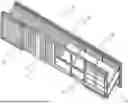
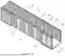
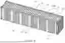
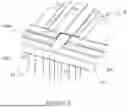
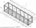
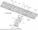
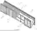
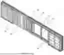
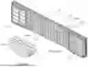


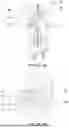


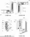
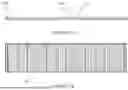

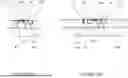


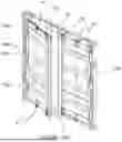


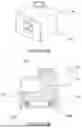
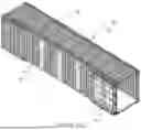


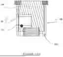


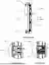
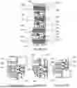

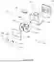
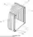
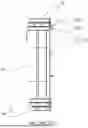
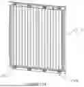
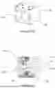
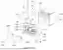
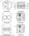


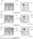
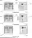

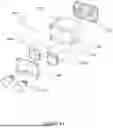


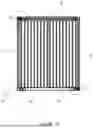
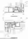


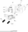
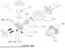
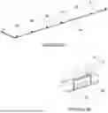

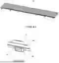
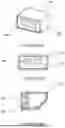
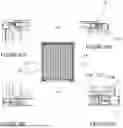
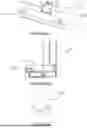
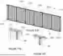


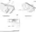
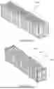
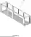
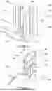

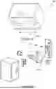
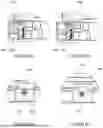


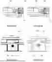


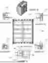
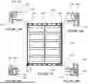

Sources:
- United States Patent and Trademark Office - verify current appl. status at the USPTO↗
Similar patent applications:
- » 20200071069
Collapsible intermodal container and a collapsible intermodal container assembly - » 20200079582
Collapsible intermodal container - » 20200079583
A Collapsible Intermodal Container Stacker and a Stacking System - » 20210171279
Collapsible intermodal container stacker and a stacking system - » 20250320056
COLLAPSIBLE INTERMODAL CONTAINER - » 20170021998
Self-collapsing stackable intermodal shipping container
Recent applications in this class:
- » 20250320056 2025-10-16
COLLAPSIBLE INTERMODAL CONTAINER - » 20240270479 2024-08-15
Folding Container - » 20240199319 2024-06-20
FOLDING TRANSPORT CONTAINER - » 20240199318 2024-06-20
Collapsible container with slidable retractable wall - » 20230365325 2023-11-16
Flat-pack shipping container - » 20230339674 2023-10-26
System and Methods for Folding a Foldable Container - » 20230076758 2023-03-09
Intermediate bulk container systems and methods of using same - » 20220396421 2022-12-15
UAV transport box - » 20220267086 2022-08-25
Flat-pack shipping container - » 20220242660 2022-08-04
Collapsible shipping container