ULTRASOUND-BASED IMAGING SENSOR
US20260055697A1
2026-02-26
19/306,789
2025-08-21
Smart Summary: A new sensor system is designed for use in deep boreholes. It has a part that connects to a downhole tool and includes an ultrasonic probe that sends out and receives sound waves. An electronic circuit collects and stores data from the probe, powered by a battery. The sensor is housed in a protective casing with a special window for the ultrasonic signals. At the other end, there is a detachable joint that is wider than the main housing. 🚀 TL;DR
Abstract:
A sensor system, for downhole sensing of a bore hole, includes: a proximal portion comprising: a proximal end of the sensor system that is configured to attach to a downhole tool; a ultrasonic probe that emits ultrasonic signals and receives reflected ultrasonic signals; an electronic circuit with a processor and a memory that collects and stores data from the ultrasonic probe; a first battery that powers the ultrasonic probe and the electronic circuit; and a housing that includes an ultrasonic window; and a distal portion comprising: a detachable joint disposed at a distal end of the sensor system. The proximal portion and the distal portion are arranged in order along a longitudinal axis of the sensor system. The detachable joint has a larger diameter than the housing.
Assignee:
- Kureha America, Inc. 8 🇺🇸 Houston, TX, United States
Applicant:
Interested in similar patents?
Get notified when new applications in this technology area are published.
Classification:
E21B47/085 » CPC main
Survey of boreholes or wells; Measuring diameters or related dimensions at the borehole using radiant means, e.g. acoustic, radioactive or electromagnetic
E21B47/16 » CPC further
Survey of boreholes or wells; Means for transmitting measuring-signals or control signals from the well to the surface, or from the surface to the well, e.g. for logging while drilling using acoustic waves through the drill string or casing, e.g. by torsional acoustic waves
Description
CROSS-REFERENCE TO RELATED APPLICATIONS
The present application claims priority to U.S. Provisional Patent Application No. 63/686,025, filed on Aug. 22, 2024, the content of which is incorporated by reference in its entirety.
BACKGROUND
Hydrocarbon extraction (e.g., hydraulic fracturing) techniques using a well system require several traversals of a bore hole with different downhole tools. Distortion of the bore hole and/or the casing (e.g., pipe) can prevent the traversal of one or more of the downhole tools. Conventional methods of inspecting the bore hole requires a stop of production and removal of all tools from the wellbore and separate deployment of imaging equipment into the bore hole. Therefore, a robust sensor system that can be deployed during production or completion operation is desirable.
SUMMARY
In general, one or more embodiments of the invention relate to a sensor system, for downhole sensing of a bore hole, that includes: a proximal portion comprising: a proximal end of the sensor system that is configured to attach to a downhole tool; a ultrasonic probe that emits ultrasonic signals and receives reflected ultrasonic signals; an electronic circuit with a processor and a memory that collects and stores data from the ultrasonic probe; a first battery that powers the ultrasonic probe and the electronic circuit; and a housing that includes an ultrasonic window; and a distal portion comprising: a detachable joint disposed at a distal end of the sensor system. The proximal portion and the distal portion are arranged in order along a longitudinal axis of the sensor system. The detachable joint has a larger diameter than the housing.
Other aspects of the invention will be apparent from the following description and the appended claims.
BRIEF DESCRIPTION OF DRAWINGS
FIG. 1A shows a diagram of a well system.
FIGS. 1B-1D shows a schematic of different bore hole deformations.
FIGS. 2A-2B show examples of a sensor system in accordance with one or more embodiments.
FIGS. 3A-3B show examples of an ultrasonic imaging technique in accordance with one or more embodiments.
FIG. 4 shows the ultrasonic imaging technique of FIGS. 3A-3B mapping a bore hole, in accordance with one or more embodiments.
FIG. 5A-5B show a detachable joint of the sensor system, in accordance with one or more embodiments.
FIG. 6 shows an electronic circuit, in accordance with one or more embodiments.
FIGS. 7A-7B show examples of a sensor system in accordance with one or more embodiments.
DETAILED DESCRIPTION
Specific embodiments of the invention will now be described in detail with reference to the accompanying figures. Like elements in the various figures are denoted by like reference numerals for consistency.
In the following detailed description of embodiments of the invention, numerous specific details are set forth in order to provide a more thorough understanding of the invention. However, it will be apparent to one of ordinary skill in the art that the invention may be practiced without these specific details. In other instances, well-known features have not been described in detail to avoid unnecessarily complicating the description.
Throughout the application, ordinal numbers (e.g., first, second, third) may be used as an adjective for an element (i.e., any noun in the application). The use of ordinal numbers is not to imply or create a particular ordering of the elements nor to limit any element to being only a single element unless expressly disclosed, such as by the use of the terms “before,” “after,” “single,” and other such terminology. Rather the use of ordinal numbers is to distinguish between the elements. By way of an example, a first element is distinct from a second element, and the first element may encompass more than one element and may succeed (or precede) the second element in an ordering of elements.
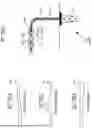
FIG. 1A shows a diagram of a well system.
In general, a hydrocarbon production facility 100 includes a rig 102 with a bore hole 104 that accesses an underground hydrocarbon reservoir. In some embodiments, the hydrocarbon production facility 100 may be extracted by hydraulic fracturing in which the geological formations are fractured to stimulate the flow of natural gas or oil and increase the yield from the well. In this process, after drilling the bore hole 104 and reinforcing with a casing 105, a string 106A and downhole tool 106B are lowered into the bore hole 104 to install one or more frac plugs 108 to create one or more isolation zones 110 (e.g., a lower wellbore zone 110B can be temporarily isolated from a process conducted in an upper zone 110A).
Hydrocarbon extraction methods often require repeatedly inserting and withdrawing the string 106A to fit different equipment to the downhole tool 106B. For example, inspecting the bore hole 104 with conventional sensor tools (e.g., sensor strings) requires a stop of production and removal of production tools from the bore hole 104 and separate deployment of completely different sensor string into the bore hole 104.
One potential risk for losing production capacity from the hydrocarbon production facility 100 is a deformation in the bore hole 104 and/or casing 105. One or more of these deformation shapes may be caused by geological movements, damage to the casing 105, or any other distortion in the bore hole 104. FIGS. 1B-1D show schematics of different bore hole deformations (e.g., helical buckling, bending deformation, shear deformation). Repeated insertion and removal of the string 106A and downhole tool 106B through these deformed regions threaten to damage the equipment or cause the equipment to jam in the bore hole 104.
Embodiments of the present invention provide an improved sensor system for imaging the bore hole 104 and casing 105 to ensure the safety of continuing operation of the hydrocarbon production facility 100. Embodiments of the present invention may be equipped on a downhole tool 106B during for dummy runs to inspect the bore hole 104. For example, before inserting a frac plug 108 into the well, the dummy run is conducted with only a pump-down tool as the downhole tool 106B. By imaging the casing 105 during a dummy run, the shape of the casing 105 can be determined in advance of transporting other equipment (e.g., frac plugs) to a desired location in the well.
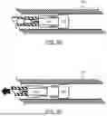
FIG. 2A shows an example of a sensor system 200, in accordance with one or more embodiments.
The sensor system 200 utilizes ultrasonic probing to measure the interior surface of the casing 105 (e.g., the distance between the sensor system 200 and the casing 105). In some embodiments, Additionally, the sensor system 200 may include additional sensors to monitor other parameters as the sensor system 200 is swept through the bore hole 104.
In some embodiments, the sensor system 200 includes a proximal portion 210 and a distal portion 230 arranged in order along a longitudinal direction of the sensor system 200. One or more of the proximal portion 210 and the distal portion 230 may be contiguous or integral with each other. Each of these sections of the sensor system 200 are described in further detail below. Furthermore, the sensor system 200 may include one or more centralizers, as described in further detail below with respect to FIGS. 7A-7B.
The proximal portion 210 includes a proximal end 213, an ultrasonic probe 214, an electronics housing 216, and a housing 224. Each of these components of the proximal portion 210 are described in further detail below.
The proximal end 213 is configured to attach the sensor system 200 to a downhole tool 106B. For example, the proximal end 213 may be a connector (e.g., threaded rod, latch) that connects to a corresponding connector on the tool 106B.
The ultrasonic probe 214 is configured to emit ultrasonic signals and receive reflected ultrasonic signals via one or more ultrasonic transducers. By measuring the amplitude, phase, and/or timing of the reflected ultrasonic signals, an image may be formed of one or more reflecting surfaces (e.g., the casing 105). The resolution of the imaging depends on the frequency of the ultrasonic signals. To obtain a clearer image, a frequency of 0.1 MHz or higher is may be used. In some embodiments, a frequency of 0.5 MHz or higher, or 1 MHz or higher may be used. To accurately detect reflected waves, a high sound pressure is required. In the ultrasonic probe 214, the sound pressure can be controlled by the applied voltage. Increasing the applied voltage increases the sound pressure, but it also increases signal noise and power consumption. From these perspectives, an applied voltage of 200 Vp-p (peak to peak) or less may be used. In some embodiments, an applied voltage of 100 Vp-p or less, or 50 Vp-p or less may be used.
The electronics housing 216 includes: an electronic circuit that includes a processor and a memory that collects and stores data from the ultrasonic probe 214; and a battery (i.e., a first battery) that powers the ultrasonic probe 214 and the electronic circuit. The configuration of the electronic circuit is described in further detail below with respect to FIG. 6. In some embodiments, the sensor system 200 is configured for stand-alone operation, separate from equipment at the surface of the well. For example, the battery powers the sensor system 200 to collect data even in configurations of the string 106A that cannot be monitored in real time by equipment at the surface. The electronic circuit is configured such that data are saved in the memory for extraction and analysis when the sensor system 200 returns to the surface.
The housing 224 may include a plastic (e.g., Polypropylene, Polyethylene, Polymethyl Methacrylate, Polyethylene Terephthalate, Polyoxymethylene, Polycarbonate, Polyvinyl Chloride), a super engineered plastic, also known as a high-performance plastic, (e.g., Polyether Ether Ketone, Polyphenylene Sulfide, Polyphthalamide, Liquid Crystal Polymer, Polysulfone, Polyetherimide, Polyamide-imide, Polytetrafluoroethylene), a glass, a ceramic (e.g., Alumina, Zirconia, Silicon Carbide, Boron Nitride, Aluminum Nitride, Silicon Nitride, Titanium Dioxide), a glass fiber reinforced plastic (GFRP), a carbon fiber reinforced plastic (CFRP), or a metal (e.g., Magnesium alloy, Aluminum alloy, Titanium alloy, Steel alloy). While these materials provide enhanced mechanical strength to the sensor system 200, it will be appreciated that other materials may be used. For example, as discussed below, the distal portion 230 may include structural reinforcing members to allow other materials for the housing 224. The housing 224 may include an ultrasonic window 225 through which the emitted ultrasonic signals are transmitted from the interior to the exterior of the sensor system 200.
In some embodiments, the housing 224 may include an ultrasonic medium (e.g., liquid, fluid, oil, or another ultrasonic amplification medium) that facilitates the transmission of the ultrasonic signals. For example, an internal cavity of the housing 224 (e.g., that accommodates the ultrasonic probe 214) may be filled with the ultrasonic medium to modify the behavior of the ultrasonic signals (e.g., reduce reflections at one or more boundaries between the ultrasonic probe 214 and the exterior of the sensor system).
In some embodiments, the housing 224 includes an ultrasonic window 225 that is at least partially transmissive or transparent to the ultrasonic signals of the ultrasonic probe 214. The housing 224 and/or the ultrasonic window 225 may have an acoustic impedance in a range of less than 20 MRayl, more preferably less than 10 MRayl, and still more preferably less than 5 MRayl. In some embodiments, the ultrasonic window 225 may be cylindrical portion of the housing 224 that overlaps the mirror 222 in a longitudinal direction of the sensor system 200. In some embodiments, the housing 224 extends in a longitudinal direction of the sensor system 200 to radially surround the proximal portion 210 of the sensor system 200. In order to mitigate a reduction in detection accuracy (e.g., from ultrasonic wave reflections at interfaces between the ultrasonic probe and the casing 105), a portion of the sensor system 200 may be angled relative to the casing 105.
By calculating the refractive properties of the housing 224 (e.g., the internal medium, the housing 224, the ultrasonic window 225), the emitted and reflected path of the ultrasonic signal can be converted into a distance between the ultrasonic probe 214 and the casing 105. As shown in FIG. 4, factoring in the geometry of the sensor system 200 allows a three-dimensional map of the casing 105 may be generated from the ultrasonic signals.
In some embodiments, the sensor system 200 includes a mirror 222 that reflects the ultrasonic signals emitted from the ultrasonic probe 214. The mirror 222 may be a material selected to reflect ultrasonic signals in the range operated by the ultrasonic probe 214. For example, the mirror is made from material whose acoustic impedance is high, such as a metal. In some embodiments, the mirror 222 is mounted at an angle with respect to a longitudinal axis of the sensor system 200 to project ultrasonic signals out of the housing 224. For example, when the ultrasonic probe 214 is configured to fire ultrasonic signals along the longitudinal axis of the sensor system 200, the mirror 222 may be oriented at 45 degrees relative to the longitudinal axis to redirect the ultrasonic signals axially out of the sensor system 200 (see FIG. 4). As described in further detail with respect to FIG. 2B, if the ultrasonic probe 214 is configured to directly emit the ultrasonic signals out of the housing 224 (e.g., disposed facing to the casing and configured to rotate about the longitudinal axis of the sensor system 200), a mirror 222 may not be required in the sensor system 200.
The distal portion 230 includes a detachable joint disposed at a distal end of the sensor system 200. The detachable joint may include: a tip portion 232 configured to separate from the distal portion 230 of the sensor system 200 (e.g., to remain in the bore hole 104); and a base portion 234 that remains with the distal portion 230 of the sensor system 200. The detachable joint may be a safety joint that separates based on a predetermined movement of the downhole tool 106B. For example, the detachable joint may be a shear out safety joint that separates based on a straight pull of the downhole tool 106B.
The detachable joint may be configured with a larger diameter than the housing 224 of the sensor system 200. Furthermore, the structural configuration (e.g., dimensions, reinforcing structures) of the detachable joint provides the sensor system 200 with enhanced strength. For example, in comparison to a rod-shape sensor geometry (e.g., a probe designed to fit in a frac plug 108), the detachable joint of the distal portion 230 is dimensioned to fit the bore hole 104 (with enough clearance for insertion and removal).
In some embodiments, the proximal portion 210 of the sensor system 200 is aligned with a central axis of the detachable joint of the distal portion 230. A linear alignment provides strength to compressive and tensile forces along the longitudinal direction of the sensor system 200. By configuring the distal portion 230 with the relatively stronger detachable joint, the engineering requirements of the other portions of the sensor system 200 (e.g., the proximal portion 210, the housing 224) are lessened.
In some embodiments, the base portion 234 of the detachable joint may include a motor housing 236 with a motor that rotates the mirror 222 about a longitudinal axis of the sensor system 200. As described below with respect to FIG. 4, rotating the mirror 222 allows the ultrasonic probe 214 to map the entire bore hole 104 in a cylindrical reference system. The motor may be connected to the mirror 222 by a shaft 223 that extends through a seal disposed between the mirror 222 and the base portion 234 of the detachable joint. In some embodiments, the housing 224 extends in a distal longitudinal direction of the sensor system 200 to radially surround the seal between the mirror 222 and the base portion 234 of the detachable joint.
In some embodiments, the motor that rotates the mirror 222 is connected to and controlled by the electronic circuit in the electronics housing 216 of the proximal portion 210. The motor housing 236 may further include a battery (i.e., a second battery) and a motor battery circuit (i.e., an independent electronic circuit and battery from the first battery and electronic circuit in the electronics housing 216 of the proximal portion 210).
FIG. 2B shows another example of the sensor system 200 in accordance with one or more embodiments.
In some embodiments, the ultrasonic probe 214 is configured to directly emit the ultrasonic signals out of the housing 224 (i.e., without a reflecting the ultrasonic signals off of a mirror 222). In FIG. 2B, the ultrasonic probe 214 is disposed facing the casing and emits ultrasonic signals radially away from the longitudinal axis of the sensor system 200. The ultrasonic probe 214 may contain a mirror (not shown) integrally attached to the tip of the ultrasonic probe 214 at an angle with respect to the longitudinal axis of the sensor system 200 to redirect the ultrasonic signals emitted from the ultrasonic probe 214 to a radial direction that extends out of the housing 224. Similar to the embodiment shown in FIG. 2A, in some embodiments, the ultrasonic emitter of the ultrasonic probe 214 is oriented along the longitudinal axis and the emitted signals may be reflected out of the housing 224 by the mirror. In such embodiments, the shaft 223 and the motor in the distal portion 230 in FIG. 2A may be omitted because the mirror may be integrally attached to the tip of the ultrasonic probe 214 at an angle with respect to the longitudinal axis of the sensor system 200 to project ultrasonic signals out of the housing 224. In some embodiments, the ultrasonic probe 214 may be mounted on a motor that is configured to rotate the ultrasonic probe 214 about the longitudinal axis of the sensor system 200. The motor may be disposed in the electronics housing 216 in the proximal portion 210 (as shown in FIG. 2B) or may be disposed in the base portion 234 of the detachable joint in the distal portion 230 (not shown). The motor may be connected to a shaft 223 with a slip ring (not shown) concentrically mounted around the shaft 223. The shaft 223 may extend through a seal disposed between the ultrasonic probe 214 and the electronics housing 216 or the base portion 234 of the detachable joint.
FIG. 3A shows an example of an ultrasonic imaging technique in accordance with one or more embodiments.
As discussed above with respect to FIG. 2A, the ultrasonic probe 214 may be configured to probe the entire bore hole 104 by using a rotating mirror 222. The ultrasonic probe 214 emits ultrasonic signals toward an angled mirror 222 to emit the ultrasonic signals toward a wall of the housing 224 and out of the sensor system 200 to the casing 105. The reflected ultrasonic signals from the casing 105 are reoriented by the mirror 222 back toward the ultrasonic probe 214.
FIG. 3B shows an example of an ultrasonic imaging technique in accordance with one or more embodiments.
As discussed above with respect to FIG. 2B, the ultrasonic probe 214 may be configured to probe the entire bore hole 104 by rotating about the longitudinal axis of the sensor system 200. The ultrasonic probe 214 directly emits ultrasonic signals radially outward from the longitudinal axis toward a wall of the housing 224 and out of the sensor system 200 to the casing 105. The reflected ultrasonic signals from the casing 105 are detected by the ultrasonic probe 214.
In either of the non-limiting examples of FIGS. 3A-3B, the motor may include an encoder to measure rotational position to calculate a map of the casing 105 (e.g., with resolution for every 1 degree rotation of the motor). The encoder may measure the rotational speed to control the imaging resolution. For example, the same sampling rate can be adjusted via the rotation speed to provide a consistent imaging resolution regardless of the radial distance between sensor system 200 and the casing 105.
FIG. 4 shows the ultrasonic imaging technique of FIGS. 3A-3B mapping a bore hole 104, in accordance with one or more embodiments.
As shown in the left portion of FIG. 4, the combination of the angle of emissions from a rotating mirror and the ultrasonic imaging techniques of FIGS. 3A-3B create an acoustic pattern that probes the entire perimeter of the casing 105. As shown in the right portion of FIG. 4, a corkscrew pattern that emits ultrasonic signals in all directions may be used to create accurate images of the interior surface of the casing 105. By controlling the sampling rate of the ultrasonic probe 214 and/or the rotational speed of the motor, the resolution of the reconstructed map from the ultrasound data can be directly controlled. Any appropriate rotational speed and sampling rate may be used.
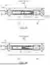
FIGS. 5A-5B show a detachable joint of the sensor system, in accordance with one or more embodiments.
As discussed above, the distal portion 230 of the sensor system 200 includes a detachable joint configured to separate a base portion 234 (that remains with the sensor system 200) from a tip portion 232. For example, the detachable joint may be a safety joint that separates based on a predetermined movement of the downhole tool 106B.
Furthermore, the structural configuration (e.g., dimensions, materials, reinforcing structures) of the detachable joint provides the sensor system 200 with enhanced strength. In comparison to a rod-shape sensor designed to fit in an annular region of a frac plug 108, the detachable joint of the distal portion 230 is dimensioned to fit the bore hole 104 (with enough clearance for insertion and removal).
The tip portion 232 of the detachable joint may be configured with the largest diameter of the sensor system 200. Any constricted section of the inner diameter of the casing 105 must contact the tip portion 232 of the detachable joint first. Accordingly, the relatively higher mechanical strength of the detachable joint protects the proximal portion 210 from contact with the casing 105 or damage from any obstruction in the bore hole 104.
In some embodiments, the detachable joint is a safety joint that separates based on a predetermined movement of the downhole setting tool. For example, if the sensor system 200 is immobilized by a constriction or an obstruction in the bore hole 104, the detachable joint can separate to free the sensor system 200 (except the tip portion 232) for recover to the surface. In some embodiments, as shown in FIG. 5B, the detachable joint is a shear out safety joint that separates based on a straight pull of the downhole setting tool 106B that the sensor system is connected to.
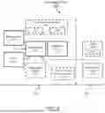
FIG. 6 shows an electronic circuit 600, in accordance with one or more embodiments.
The electronic circuit 600 includes a microcontroller 610, an ultrasonic probe 214, a memory 620, and a battery circuit 630. In some embodiments, the electronic circuit 600 further includes one or more of: an environmental sensor 640; a localization sensor 650; a motor 660; a motor battery circuit 670; and optionally an external signal detection sensor 680. Each of these subcomponents are described in further detail below.
The microcontroller 610 is connected to and controls functions of the sensor system 200 and subcomponents therein. In particular, the microcontroller 610 is configured to control the ultrasonic probe 214 to emit ultrasonic signals and process the received/reflected ultrasonic signals. The microcontroller 610 gathers, saves, and manipulates data from the ultrasonic probe 214 and any other sensors in the sensor system 200. The microcontroller 610 may include one or more processors, application specific integrated circuits (ASIC), and/or any other processing device.
In some embodiments, the microcontroller 610 continuously operates the ultrasonic probe 214 (as an imaging sensor) and other sensors (e.g., the environmental sensors 640, the localization sensor 650, and/or the external signal detection sensor 680). Alternatively, the microcontroller 610 may monitor one or more of the sensors for a predetermined condition to start or stop operation of subcomponents of the sensor system 200. To reduce power consumption, conditions such as temperature, sensor tilt, moving distance, and external signals (e.g., infrared, radio waves, magnetic fields, and sound waves) can be set to activate one or more sensors of the sensor system (e.g., the ultrasonic probe 214, the localization sensor 650). Additionally, to prevent unexpected battery overheating and damage, one or more components of the sensor system 200 can be set to stop operating when a certain temperature is exceeded.
The memory 620 is connected to the microcontroller 610 to save and store data from the ultrasonic probe 214. The memory 620 may store raw sensor data (e.g., ultrasonic signals, temperature, pressure, electrical conductivity) and/or processed data (e.g., distance information from the ultrasonic probe 214). The memory 620 may store raw sensor data and/or processed data from any other sensors in the sensor system 200.
The battery circuit 630 includes a battery (i.e., the first battery) that is connected to and provides power to the electronic circuit 600. In some embodiments, the battery circuit 630 powers the electronic circuit 600 in the proximal portion 210 of the sensor system 200. In some embodiments, the battery circuit 630 powers the entire sensor system 200.
The environmental sensor(s) 640 may include a temperature sensor 642 and/or a pressure sensor 644 to provide additional information for processing the ultrasonic signals. For example, the refractive index of the transmissive or reflective materials in the sensor system 200 may vary with temperature and/or pressure as the sensor system 200 traverses the bore hole 104. By measuring these quantities, the transformation of the data collected by the ultrasonic probe 214 may be accurately converted into a map of the casing 105. Additionally, the environmental measurements may be used to protect the sensor system 200 (e.g., start and stop timing to save battery power; prevent damage from heating).
The localization sensor 650 may be configured to determine position information of the sensor system 200 within the bore hole 104. For example, the localization sensor 650 may include an accelerometer, gyrometer, and/or an inertial positioning processor to determine a relative or absolute orientation/position of the sensor system 200. Alternatively, the localization sensor 650 may include a casing collar locator that is configured to detect distortion of magnetic lines of flux when passing a location at which the metallic casing is enlarged by a collar. Furthermore, the localization sensor 650 may provide information to microcontroller 610 (e.g., to control the ultrasonic probe 214 (e.g., start/stop of acquisition, manage sampling rate), to control the motor 660).
The motor 660 may be disposed in the proximal portion 210 or the distal portion 230 of the sensor system 200. The motor 660 may be connected to the ultrasonic probe 214 or the mirror 222 by a shaft 223. The motor 660 may include an encoder 662 that measures a position and/or speed of the motor 660.
The motor battery circuit 670 may include a battery (i.e., a second battery) that powers the motor 660. The motor battery circuit 670 may further include a second microprocessor that manages the components of the electronic circuit in the distal portion 230 of the sensor system 200. In some embodiments, the motor 660 and/or motor battery circuit 670 are connected to the microcontroller 610.
The external signal detection sensor 680 may be configured to detect signals such as infrared, radio waves, magnetic fields, and sound waves, that are transmitted from the surface. For example, the external signal detection sensor 680 may include an infrared receiver, a radio receiver, a magnetometer, and an acoustic sensor. The external signal detection sensor 680 may provide information to microcontroller 610 (e.g., to control the ultrasonic probe 214 (e.g., start/stop of acquisition, manage sampling rate), to control the motor 660).
In one or more embodiments, the above subcomponents of the electronic circuit 600 may be omitted, included in multiple quantities, combined as a single subcomponent (e.g., microcontroller 610 directly controls the motor 660 without a motor battery circuit 670), and/or disposed in other portions of the electronic circuit 600 (e.g., proximal, intermediate, distal portions).
In addition, it will be appreciated that other subcomponents beyond those listed above may be included, internally or externally, as a subcomponent of the electronic circuit 600 without departing from the scope of the present disclosure. For example, while the following embodiments are described with respect to an internal memory, the invention may be include a removable storage device.
As discussed above, embodiments of the invention may be implemented on virtually any type of electronic circuit 600. The electronic circuit 600 may include one or more processor(s) or microcontrollers 610, associated memory 620 (e.g., random access memory (RAM), cache memory, flash memory), one or more storage device(s), and numerous other elements and functionalities. The microcontroller(s) 610 may be an integrated circuit for processing instructions and may include one or more cores, or micro-cores of a processor. The electronic circuit 600 may also include one or more input/output device(s), such as an external storage or communication port. In some embodiments, the electronic circuit 600 may be configured to connect to a network (e.g., a local area network (LAN), a wide area network (WAN) such as the Internet, mobile network, or any other type of network) via a network interface connection (not shown). Many different types of electronic circuit 600 exist, and the aforementioned subcomponents of the electronic circuit 600 may take other forms.
Software instructions in the form of computer readable program code to perform embodiments of the invention may be stored, in whole or in part, temporarily or permanently, on a non-transitory computer readable medium such as a storage device, a flash memory, a physical memory, or any other computer readable storage medium. Specifically, the software instructions may correspond to computer readable program code that when executed by a processor(s), is configured to perform embodiments of the invention.
FIGS. 7A-7B show examples of a sensor system 200, in accordance with one or more embodiments.
In some embodiments, one or more centralizers 240 are optionally incorporated into the sensor system 200 to maintain axial alignment of the tool 106B within the wellbore during operations. The centralizer 240 may vary in design, configuration, and quantity depending on the operational requirements and wellbore geometry. For example, the maximum diameter of the centralizer 240 is configured larger than the housing 224 of the sensor system 200. The centralizer 240 may include, but is not limited to, an adjustable spring-type configuration comprising a mandrel (central portion) and radially expandable bows or arms 242 with rollers 244. The rollers 244 help reduce contact friction between the casing 105 or tubing and the centralizer 240. The selection of centralizer type may be based on factors such as the internal diameter of the tubing and casing 105, the presence of restrictions, and the mechanical properties of the tool string 106.
In various implementations, a single centralizer 240 may be positioned at a strategic location along the longitudinal axis of the sensor system 200, or multiple centralizers 240 may be distributed along the longitudinal axis to provide enhanced stability and alignment. The number and spacing of centralizers 240 may be determined based on the length, weight, and flexibility of the sensor system 200, as well as the anticipated downhole conditions. Each centralizer 240 may be independently adjustable or fixed, and may include features such as fishing necks, customizable connections, or integrated locking mechanisms. The inclusion and configuration of centralizers 240 are optional and may be tailored to specific embodiments to optimize tool performance, reduce wear, and improve the accuracy of downhole operations.
In some embodiments, the centralizer 240 may be positioned at the distal portion 230 in the place of the tip portion 232. Alternatively, the centralizer 240 may be positioned at a strategic location on the proximal portion 210 or the proximal end 213 connecting with the tool 106B. The sensor system 200 can contain any number of centralizers 240 at any location (e.g., at the distal portion 230, the proximal portion 210, the proximal end 213, and any combination thereof) to maintain the ultrasonic probe 214 at a cross-sectional center of the casing and tubing. For example, the centralizer 240 may be installed at each end of the housing 224 that allows the sensor system 200 to be conveyed within the wellbore while being held in a centered position of casings 105.
Although the disclosure has been described with respect to a limited number of embodiments, those skilled in the art, having benefit of this disclosure, will appreciate that various other embodiments may be devised without departing from the scope of the present invention. Accordingly, the scope of the invention should be limited only by the attached claims.
Claims
What is claimed is:1. A sensor system for downhole sensing of a bore hole, the sensor system comprising:
a proximal portion comprising:
a proximal end of the sensor system that is configured to attach to a downhole tool;
a ultrasonic probe that emits ultrasonic signals and receives reflected ultrasonic signals;
an electronic circuit with a processor and a memory that collects and stores data from the ultrasonic probe; and
a first battery that powers the ultrasonic probe and the electronic circuit;
a housing that includes an ultrasonic window; and
a distal portion comprising:
a detachable joint disposed at a distal end of the sensor system;
wherein the proximal portion and the distal portion are arranged in order along a longitudinal axis of the sensor system, and
wherein the detachable joint has a larger diameter than the housing.
2. The sensor system of claim 1,
wherein the detachable joint includes:
a tip portion configured to separate from the distal portion of the sensor system to remain in the bore hole; and
a base portion that remains with the distal portion of the sensor system.
3. The sensor system of claim 1,
wherein the detachable joint has the largest diameter of the sensor system.
4. The sensor system of claim 1,
wherein the ultrasonic probe is configured to emit ultrasonic waves perpendicularly to the longitudinal axis of the sensor system.
5. The sensor system of claim 4,
wherein the ultrasonic probe includes a motor that rotates the ultrasonic probe about the longitudinal axis of the sensor system; and
wherein the motor is connected to and controlled by the electronic circuit.
6. The sensor system of claim 5,
wherein the motor is connected to the ultrasonic probe by a shaft that extends through a seal between the ultrasonic probe and the motor.
7. The sensor system of claim 1, further comprising:
a mirror that reflects the ultrasonic signals,
wherein the ultrasonic probe is configured to face the mirror and is aligned with a central axis of the mirror.
8. The sensor system of claim 7,
wherein the ultrasonic probe includes:
a motor that rotates the mirror about the longitudinal axis of the sensor system; and
a second battery that powers the motor,
wherein the motor is connected to and controlled by the electronic circuit.
9. The sensor system of claim 8,
wherein the motor is connected to the mirror by a shaft that extends through a seal between the mirror and the detachable joint.
10. The sensor system of claim 7,
wherein the mirror integrally constitutes the ultrasonic probe.
11. The sensor system of claim 10,
wherein the ultrasonic probe includes a motor that rotates the ultrasonic probe about the longitudinal axis of the sensor system, and
wherein the motor is connected to and controlled by the electronic circuit.
12. The sensor system of claim 1,
wherein the housing comprises a plastic, a super engineered plastic, a glass, a ceramic, a glass fiber reinforced plastic (GFRP), a carbon fiber reinforced plastic (CFRP), or a metal.
13. The sensor system of claim 1,
wherein the electronic circuit includes a localization sensor that determines position information of the sensor system within the bore hole.
14. A sensor system for downhole sensing of a bore hole, the sensor system comprising:
a proximal portion comprising:
a proximal end of the sensor system that is configured to attach to a downhole tool;
a ultrasonic probe that emits ultrasonic signals and receives reflected ultrasonic signals;
an electronic circuit with a processor and a memory that collects and stores data from the ultrasonic probe; and
a first battery that powers the ultrasonic probe and the electronic circuit;
a housing that includes an ultrasonic window;
a base portion disposed at a distal end of the sensor system; and
a centralizer with a larger diameter than the housing,
wherein the centralizer is configured to position the sensor system at a centered position within a casing of the bore hole.
15. The sensor system of claim 14,
wherein the sensor system includes at least two centralizers disposed on opposite ends of the housing.
16. The sensor system of claim 15,
wherein the at least two centralizers include:
a first centralizer attached to the base portion; and
a second centralizer attached as the proximal end of the sensor system and is configured to attach to the downhole tool.
17. The sensor system of claim 15,
wherein the at least two centralizers are independently adjustable.
18. The sensor system of claim 1,
wherein the ultrasonic probe is configured to emit ultrasonic waves perpendicularly to the longitudinal axis of the sensor system.
19. The sensor system of claim 4,
wherein the ultrasonic probe includes a motor that rotates the ultrasonic probe about the longitudinal axis of the sensor system; and
wherein the motor is connected to and controlled by the electronic circuit.
Images & Drawings included:


Sources:
- United States Patent and Trademark Office - verify current appl. status at the USPTO↗
Recent applications in this class:
- » 20260009322 2026-01-08
MULTI-CASING EVALUATION USING MULTI-FREQUENCY, NON-COLLOCATED, INDUCTION MEASUREMENTS - » 20260002437 2026-01-01
PROFILE IDENTIFICATION FOR DOWNHOLE POSITIONING USING NON-CONTACTING ULTRASONIC WAVES - » 20250354480 2025-11-20
CASING THICKNESS DETERMINATION FROM PULSE-ECHO ULTRASONIC MEASUREMENTS - » 20250243752 2025-07-31
DISTRIBUTED FIBER SENSING IN A PACKER FOR PERMANENT CASING AND FORMATION DEFORMATION MONITORING - » 20250243751 2025-07-31
LWD SONIC EVALUATION OF FORMATION HETEROGENEITY - » 20250172066 2025-05-29
PREDICTING WELLBORE DIAMETERS - » 20250075614 2025-03-06
TUBING ECCENTRICITY EVALUATION USING ACOUSTIC SIGNALS - » 20240360755 2024-10-31
ELECTROMAGNETIC PIPE INSPECTION WITH AZIMUTHAL DEFECT EVALUATION - » 20240175349 2024-05-30
UNTETHERED DOWNHOLE TOOLS AND RELATED METHODS OF GENERATING VERTICAL SEISMIC PROFILES - » 20240167377 2024-05-23
APPARATUS AND METHOD FOR CHARACTERIZING LINER AND ANNULUS PROPERTIES WITH A GAMMA-GAMMA TOOL
Recent applications for this Assignee:
- » 20250362558 2025-11-27
PIEZOELECTRIC OPTICAL ELEMENT AND SYSTEM - » 20250300576 2025-09-25
ENERGY HARVESTING SYSTEM UTILIZING PVDF PIEZOELECTRIC FILM - » 20250282656 2025-09-11
PIEZOELECTRIC SYSTEM AND METHOD FOR PER- AND POLY-FLUOROALKYL SUBSTANCE DEGRADATION - » 20240247581 2024-07-25
SYSTEM AND METHOD FOR TRACKING A STATE OF DISSOLVABLE DOWNHOLE TOOLS - » 20230345839 2023-10-26
PIEZOELECTRIC FILM WITH CARBON NANOTUBE-BASED ELECTRODES - » 20230280857 2023-09-07
Touch sensing using polyvinylidene fluoride piezoelectric film - » 20230278009 2023-09-07
DEGRADABLE ADSORBENT AND METHOD OF REMOVING IMPURITY FROM FLUID