Tunnel Lining Method and Apparatus
US20260055705A1
2026-02-26
18/856,824
2023-04-12
Smart Summary: A new method is designed to line tunnels using special injectors that are placed next to the tunnel's inner surface. These injectors help to apply and compress a lining material, which can also be crushed and dewatered if needed. As the injectors release the lining material, they push the apparatus forward. There is also a system of articulated shuttering at the back of the apparatus to support the lining process. The injectors can be arranged to match the shape of the tunnel being lined. 🚀 TL;DR
Abstract:
A method of lining a tunnel comprises providing a plurality of injectors (7) on an apparatus, the injectors being positioned adjacent an internal tunnel surface (6) or (41) and using the injectors to place and compress and, if required, crush the solid particles of, and dewater the lining material (5) to form a structural tunnel lining. The apparatus is moved forward by the pressure exerted by the injectors (7) as they discharge the lining material. Articulated shuttering for the tunnel lining is provided on a trailing side of the apparatus. The injectors (7) can be arranged on an apparatus having a cross-section corresponding to a cross-section of a tunnel to be lined.
Applicant:
Interested in similar patents?
Get notified when new applications in this technology area are published.
Classification:
E21D11/105 » CPC main
Lining tunnels, galleries or other underground cavities, e.g. large underground chambers; Linings therefor; Making such linings , e.g. by assembling; Lining with building materials with concrete cast ; Shuttering also lost shutterings, e.g. made of blocks, of metal plates or other equipment adapted therefor Transport or application of concrete specially adapted for the lining of tunnels or galleries ; Backfilling the space between main building element and the surrounding rock, e.g. with concrete
E21D9/0621 » CPC further
Tunnels or galleries, with or without linings; Methods or apparatus for making thereof ; Layout of tunnels or galleries; Making by using a driving shield, i.e. advanced by pushing means bearing against the already placed lining Shield advancing devices
E21D11/10 IPC
Lining tunnels, galleries or other underground cavities, e.g. large underground chambers; Linings therefor; Making such linings , e.g. by assembling; Lining with building materials with concrete cast ; Shuttering also lost shutterings, e.g. made of blocks, of metal plates or other equipment adapted therefor
E21D9/06 IPC
Tunnels or galleries, with or without linings; Methods or apparatus for making thereof ; Layout of tunnels or galleries Making by using a driving shield, i.e. advanced by pushing means bearing against the already placed lining
Description
This Application is the U.S. National Phase under 35 U.S.C. §371 of PCT Application No. PCT/GB2023/050981 filed 12 Apr. 2023, entitled “TUNNEL LINING METHOD AND APPARATUS,” which claims the priority of Great Britain Application No. GB 2205597.4 filed 14 Apr. 2022 entitled “TUNNEL LINING METHOD AND APPARATUS;” and this U.S. National Phase Application claims the priority and the benefit of each of the foregoing Applications which are hereby incorporated herein by reference in their entireties.
FIELD OF THE INVENTION
The present invention relates to tunnelling methods and tunnelling structures.
BACKGROUND AND DISCUSSION OF THE RELATED ART
We are seeing rapid population growth and explosive urbanisation around the world, and this is feeding a fast-growing demand to increase the utilisation of underground space. The construction of new underground spaces by tunnelling is therefore rapidly increasing. It is recognised however that quicker, cheaper, safer, and more sustainable methods to construct new tunnels and to rehabilitate existing tunnels are required.
A variety of tunnelling technologies are currently available. The selection of the optimum solution is dependent upon a range of factors including the prevailing ground conditions and, on the form, and functions of the tunnel.
Tunnels of a constant geometry are today generally constructed using a Tunnel Boring Machine (TBM). Except for competent hard rock applications which may not require a tunnel lining to be installed, most TBM-constructed tunnels use precast concrete segments installed in a ring to provide the permanent support of the ground, to resist groundwater pressures and to provide a robust surface from which the TBM pushes itself forward using hydraulic thrust cylinders.
For practical construction purposes (such as steering), a TBM excavates a larger cross-sectional area than taken up by the permanent segmental lining. The annular gap between the outside of the segmental tunnel lining and the ground is typically filled with a cementitious grout or mortar.
The precast concrete segments which form the tunnel lining are manufactured in specialist precast concrete factories. These factories can be located at the tunnel construction site or off-site.
If sufficient land is available on the tunnel construction site for the segment manufacturing factory and for the segment storage stock yard (and if planning authorities permit), a decision may be made to manufacture the segments at the site of tunnel construction. Such facilities are however expensive and are typically decommissioned and removed at the end of tunnel construction.
If the segments are manufactured off-site (often at a significant distance from the site of the tunnel construction), the segments must be transported to the tunnel construction site from the precast factory. Typically, this will involve a significant amount of costly and time-consuming rehandling and increases the risk of accidental damage.
The segment manufacturing process will be briefly described below.
Specialist moulds manufactured to exacting tolerance are first manufactured (typically from fabricated steel). To keep pace with tunnel construction, many steel moulds are required and each mould in a complete ring is likely to have slightly different dimensions (requiring bespoke manufacture).
The fabricated moulds are transported to the precast factory.
At the precast factory, any accessories such as water sealing gaskets, bolts, dowels, grout holes etc. are fitted to the mould and then the concrete, along with the required means of reinforcing the concrete are then placed in the mould.
The concrete must then gain sufficient strength before it can be demoulded, and frequently external sources of heat are added during the curing process to reduce this time.
Once the concrete has attained sufficient strength, it is removed from its mould. It is then placed on a transporter and taken to a temporary storage yard at the precast factory. Once the segments have attained their design strength (typically at 28 days) they can then be loaded onto another mode of transport (typically a lorry, train or barge) for delivery to the tunnel construction site. At the tunnel construction site, the segments are lifted from the transporter and then placed in the segment storage yard at the jobsite.
As tunnelling proceeds, the segments are transported from the segment storage yard to the tunnel face. This process alone can involve several transfers and turning and sorting of each segment along the way.
At the tunnel face, the TBM's segment erector picks up and places each segment to form the complete tunnel lining.
Once a complete tunnel ring is formed, the annular gap between the segments and the ground is filled with a suitable grout or mortar, typically as the excavation for the next tunnel ring is underway.
The current process of manufacturing, handling, placing, and grouting a segmental lining is therefore labour intensive, slow, and expensive. Furthermore, the typically hard and brittle concrete used to form the segments is also often damaged during the handling and building process and this can lead to significant additional costs and quality problems related to the watertightness and long-term durability of the tunnel.
Tunnels constructed using TBMs typically do not excavate and advance continuously. Normally, the advance is halted once the complete length of a ring has been excavated and then the ring can be built and then excavation recommences. The ring build time can be significant and slows the overall output of the tunnelling process. As speed of tunnel advance and cost are very closely linked, this interrupted process also increases costs.
Some forms of TBM can however work in so called “continuous mining” mode. This mode is rare however, and currently used to construct a small proportion (less than 0.1%) of the tunnels built to date.
These “continuous mining” TBMs enable the tunnel to be excavated continuously without stopping for ring building. These machines require significantly longer thrust cylinders which results in TBMs which are very long. Such machines cannot easily negotiate curves and are therefore only used to construct relatively straight tunnels.
In the case of existing tunnels which require a new tunnel lining to be installed for rehabilitation and/or strengthening, it is typical to use static insitu tunnel forms (also known as formwork or shutters). Concrete is placed between the form and the existing tunnel substrate.
Typically, the insitu forms (normally precision formed from fabricated steel) will be designed and manufactured for a specific project and typically do not get used again on future projects. Pour lengths are typically between 3 m and 12 m and progress is comparatively slow as the concrete must gain sufficient strength before the form can be removed (stripped), cleaned, moved, and reset. Ideally this cycle takes no more than 24 hours but often is much longer.
Insitu concrete linings are also difficult to form defect-free and special care must be taken to properly distribute and compact the lining concrete. Voids at the top of the tunnel (known as the tunnel crown) also typically need to be filled using a secondary grouting process. Restrained concrete shrinkage can also create unwanted cracking that can adversely affect the long-term functionality of the tunnel.
Insitu concrete linings formed with static shutters are vulnerable to cracking due to shrinkage and thermal effects. To enhance the watertightness of such linings, features such as crack inducers, waterbars and grout injection tubes may be installed to help manage the cracking of the concrete, but seldom can the problem be eradicated.
Frequently a high level of watertightness is required and therefore it is common to install a continuous waterproof membrane sandwiched between two concrete layers. These membranes are applied either as sheets or can be sprayed. They are time consuming and costly to install and high standards of workmanship are required to ensure a defect-free lining.
SUMMARY OF THE INVENTION
The present disclosure describes a new process to rapidly form a tunnel lining either during construction of a new tunnel (i.e., synchronous with excavation) or to rehabilitate and/or strengthen an existing tunnel (i.e., non-synchronous with excavation). The new process is referred to herein as slipform tunnelling and is suitable to be considered as a highly beneficial alternative to currently available tunnelling and tunnel lining technologies.
The method and apparatus to line a tunnel whilst it is being excavated will be referred to as the synchronous slipform tunnel lining process.
The method and apparatus to line an existing tunnel will be referred to as the non-synchronous slipform tunnel lining process.
The present invention provides a method of lining a tunnel, comprising providing a plurality of injectors on an apparatus, the injectors being positioned adjacent an internal tunnel surface facing away from the direction of travel parallel to, or at an angle to, a centreline of the tunnel, using the injectors to place and compress tunnel lining material to form a structural tunnel lining, and moving the apparatus forwards by the pressure exerted by the injectors as the tunnel lining material is discharged, articulated shuttering for the tunnel lining being provided on a trailing side of the apparatus. During the placing process the high pressure will, if required, also crush the solid particles, and remove excess water from the tunnel lining material.
The tunnel lining material, referred to herein as slipform tunnel lining material (STLM), is not the subject of the present invention.
The term “internal tunnel surface” means the ground-in the case of a new tunnel being excavated, or an existing unlined tunnel-or an existing tunnel lining.
The injectors may be provided on an apparatus having a cross-section corresponding proportionally to a cross-section of a tunnel to be lined. The injectors may be arranged around a periphery of the apparatus and fed with STLM from feed lines located within the apparatus.
Excess water may be removed from the tunnel lining material through the injectors, in the case of injectors with active dewatering or to the ground in the case of passive dewatering.
Where the tunnel pre-exists and the method comprises rehabilitating and/or strengthening the tunnel, the apparatus is steered and braked using wheels and/or skids thereon.
The present invention also provides an apparatus for lining a tunnel, comprising a plurality of injectors for placing and compressing STLM on an internal tunnel surface, to form a structural tunnel lining and for moving the apparatus forwards by the pressure exerted by the injectors as the STLM is discharged, the injectors being oriented with respect to the apparatus to face away from the direction of travel parallel to, or at an angle to, a centreline of the tunnel, and articulated shuttering for the tunnel lining, provided on a trailing side of the apparatus, the shuttering comprising mutually articulated rings of plates, and rods extending through apertures in the rings to constrain the degree of relative displacement of the rings.
The injectors may be arranged around a periphery of the apparatus, feed lines being located within the apparatus for feeding STLM to the injectors.
An angle between an axis of the injectors along which tunnel lining material is ejected and a longitudinal axis of the apparatus may be variable.
Each injector includes a piston slidable within a cylinder to expel STLM therefrom. The piston may include an injector head having holes for removing excess water from the STLM through the injector.
The apparatus may include wheels and/or skids for steering and braking the apparatus. The apparatus may include at least one peripheral seal for retaining the ejected STLM against the internal surface. The seal comprises a minimum of two rows of wire brushes which are continuously fed with a specially formulated tail seal grease The apparatus may include a control system for controlling injection of the STLM, cleaning of the injectors and steering and braking in the case of the non-synchronous apparatus.
Five different injector designs are proposed (Types A, B, C, D, E), and are used in conjunction with one of three injector head designs (Types X, Y, Z). The selection of a particular injector and injector head for a project will depend upon the form and function of the tunnel, the prevailing ground and groundwater conditions and on the nature of the selected STLM.
In certain situations, such as a planned or unplanned stoppage, liquid admixtures can be introduced to prevent discontinuities between sections of the tunnel lining (known as “cold-joints”) which could create water paths and planes of weakness through the tunnel lining. This feed line may also be used systematically to add liquid mix components simultaneously with the filling of the injector with STLM (i.e., point of placement mixing).
The process is suitable for the construction of any size and any geometric form of tunnel. Examples of such geometric forms can be found in FIG. 10.
It is recognised that the underground construction environment is harsh for both equipment and personnel. The present disclosure recognises this and has been designed with simplicity and robustness as a guiding principle and intrinsically embodies processes to clean and maintain the apparatus to ensure continuous optimal performance.
The structural components of the apparatus will be manufactured from strong wear-resistant steels. In areas of highest expected wear, these steel components will be supplemented with surface-applied wear-enhancing coatings.
Notwithstanding the measures embodied in the apparatus to resist wear, it is recognised that over long and sustained use, that wear is inevitable and indeed unavoidable. The apparatus has therefore been designed to enable every wear component to be easily serviced or replaced insitu underground. This is true for both the synchronous and non-synchronous forms of this embodiment.
The present disclosure process also lends itself much more readily to remote operation than conventional modes of TBM tunnelling, since ring building and grouting are eliminated, and in a non-synchronous environment insitu static shutters are not required. It is proposed that both the synchronous and the non-synchronous machines would be operated remotely from the surface with only services and maintenance personnel required in the tunnel. This would further enhance the safety of the overall process and reduce costs.
Both the synchronous and non-synchronous processes can form tunnel linings significantly quicker and cheaper than current technologies as they are both continuous methods of construction unlike the existing technologies and extract maximum performance from the materials used.
The synchronous process eliminates two significant steps that are present in current state-of-the-art processes, namely ring building and grouting of the annulus.
The non-synchronous process eliminates the need to erect, strip, clean, move and re-erect static shutters.
The synchronous apparatus is considerably shorter than a conventional TBM allowing much tighter curves to be negotiated.
The synchronous apparatus does not require any over-cut for steering purposes, therefore reducing over-excavation and ground movements that could damage the existing built environment.
The synchronous apparatus places the STLM under high pressure between the articulated shutter and the ground. If weak or porous ground is present, the pressurised lining material will compress and permeate the ground to improve its characteristics. Similarly, if voids are present in the ground, the STLM will fill these voids until they are full. The apparatus cannot progress forward until a sufficient reaction is generated, thereby ensuring that all voids will be filled.
In both the synchronous and non-synchronous processes, the slipform tunnel lining material (STLM) can be varied to suit the prevailing conditions. As the apparatus includes multiple inlet ports, STLM of different properties and performance can be introduced at different points both longitudinally and circumferentially. In zones requiring higher strength, for instance, (either in compression, flexure, or direct tension) the SLTM mix composition can be changed and the fibre reinforcement enhanced by use of a greater quantity of fibre reinforcement or by use of a higher performing fibre type. Similarly, in zones with heightened concerns regarding water infiltration and watertightness, the STLM can be further enhanced to reduce its permeability, reduce or eliminate cracking, and promote self-healing.
In both the synchronous and non-synchronous processes, the structural tunnel lining is formed using high pressure injectors which rapidly create a strong mechanical matrix of the composite STLM. In the short-term the process is not reliant on the normal chemical processes associated with the setting and hardening of concrete and is therefore much quicker.
The articulated slipform shutter is sufficiently strong to resist the high imposed loading from the injectors and other imposed loads whilst also remaining sufficiently flexible to accommodate changes to both horizontal and vertical alignments. The sealing systems ensures that the articulated shutter can negotiate tight curves whilst also remaining watertight.
BRIEF DESCRIPTION OF THE DRAWINGS
The accompanying drawings, which are included to provide a further understanding of embodiments of the present disclosure, and solely as way of an example, are incorporated in and constitute a part of this specification, illustrate embodiments of the present disclosure and together with the description serve to explain the principles of embodiments of the present disclosure.
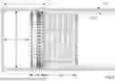
FIG. 1 is a perspective longitudinal cross-section through apparatus according to a synchronous embodiment of the invention.
FIGS. 2, 3, 4, 5 & 6 are various perspective views of the synchronous apparatus.
FIGS. 7 and 8 are perspective views of the synchronous apparatus. FIG. 7 is a perspective view from the front and FIG. 8 is a longitudinal cross-section.
FIG. 9 is a true section through the synchronous process.
FIG. 10 is some examples of the types of tunnel geometry that can be formed using the process of the current disclosure.
FIGS. 11, 12, 13 and 14 show the first injector configuration-Type A fitted with a Type X injector head which incorporates active dewatering.
FIGS. 15 & 16 show an exploded view of the Type A injector fitted with a Type X injector head.
FIGS. 17, 18 & 19 show the operating modes of the Type A Injector. FIG. 17 shows the piston at maximum retraction and the injection chamber filled with STLM. FIG. 18 shows the limit of forward stroke of the injector under normal operation. FIG. 19 shows the injector piston is its maximum forward position to allow a connection between the flushing circuit and the STLM feed line for cleaning purposes.
FIGS. 20, 21, 22 & 23 show the second type of injector-Type B-fitted with a Type X injector head and incorporating the active dewatering system.
FIGS. 24, 25 & 26 show the operating modes of the Type B Injector. FIG. 24 shows the piston at maximum retraction and the injection chamber filled with STLM. FIG. 25 shows the limit of forward stroke of the injector under normal operation. FIG. 26 shows the injector piston is its maximum forward position to allow a connection between the flushing circuit and the STLM feed line for cleaning purposes.
FIGS. 27, 28, 29 & 30 show the third type of injector-Type C-fitted with a Type Y injector head which relies upon passive dewatering to the ground or no dewatering.
FIGS. 31 & 32 show the operating modes of the Type C Injector. FIG. 31 shows the piston at maximum retraction and the injection chamber filled with STLM. FIG. 32 shows the maximum limit of forward stroke of the injector under normal operation.
FIGS. 33, 34, 35 & 36 show the fourth type of injector-Type D-fitted with a Type Z injector head which incorporates active dewatering.
FIGS. 37, 38 & 39 show the operating modes of the Type D Injector. FIG. 37 shows the piston at maximum retraction and the injection chamber filled with STLM. FIG. 38 shows the limit of forward stroke of the injector under normal operation. FIG. 39 shows the injector piston is its maximum forward position to allow a connection between the flushing circuit and the STLM feed line for cleaning purposes.
FIGS. 40, 41, 42 & 43 show the fifth type of injector-Type E-fitted with a Type Y injector head and relying upon passive dewatering to the ground or no dewatering.
FIGS. 44 & 45 show the operating modes of the Type E Injector. FIG. 44 shows the piston at maximum retraction and the injection chamber filled with STLM. FIG. 45 shows the maximum limit of forward stroke of the injector under normal operation.
FIGS. 46, 47 & 48 are perspective views of the Types X, Y and Z injector heads.
FIGS. 49, 50, 51, 52 & 53 are various perspective views of the non-synchronous apparatus fitted with steering and braking wheels.
FIG. 54 is a longitudinal perspective cross-section through the non-synchronous apparatus fitted with steering and braking wheels.
FIGS. 55 & 56 show how the angle of the injectors can be varied to produce the required amount of longitudinal thrust.
FIGS. 57 & 58 show the non-synchronous steering and braking wheel arrangement. FIG. 57 is an exploded view of the actuator and wheel. FIG. 58 shows the bulkhead and wire brush seals arrangement relative to the wheel.
FIG. 59 is a perspective view of the non-synchronous steering and braking wheel (bulkhead omitted for clarity).
FIGS. 60 & 61 are cross-sections through the non-synchronous steering and braking wheel. FIG. 60 shows details of the actuator.. FIG. 61 shows details of the wheel arrangement.
FIGS. 62, 63 & 64 show the range of movement that the non-synchronous braking and steering wheel can accommodate. FIG. 62 shows the wheel actuator at minimum extension. FIG. 63 shows the wheel actuator halfway between maximum and minimum extension. FIG. 64 shows the wheel actuator at maximum extension.
FIGS. 65 & 66 show the non-synchronous wire brush arrangement and how this is fitted to the bulkhead.
FIGS. 67, 68, 69, 70 & 71 are various perspective views of the non-synchronous apparatus fitted with steering and braking skids.
FIG. 72 is a longitudinal perspective cross-section through a non-synchronous apparatus fitted with steering and braking skids.
FIGS. 73 & 74 show the non-synchronous steering and braking skid arrangement. FIG. 73 is an exploded view of the actuator and skid. FIG. 74 shows the bulkhead and wire brush seals arrangement relative to the skid.
FIG. 75 is a cross-section through the non-synchronous steering and braking skid. FIG. 75 shows details of the actuator.
FIG. 76 is a cross-section through the non-synchronous steering and braking skid. FIG. 76 shows details of the skid arrangement.
FIGS. 77, 78 & 79 show the range of movement that the non-synchronous braking and steering skid can accommodate. FIG. 77 shows the skid actuator at minimum extension. FIG. 78 shows the skid actuator halfway between maximum and minimum extension. FIG. 79 shows the skid actuator at maximum extension.
FIGS. 80, 81, 82, 83 & 84 are various perspective views of the non-synchronous apparatus fitted with steering and braking wheels and skids.
FIG. 85 is a longitudinal perspective cross-section through the non-synchronous apparatus fitted with a combination of steering and braking wheels and steering and braking skids.
FIGS. 86 & 87 are perspective views of the articulated shutter. FIG. 86 is a perspective view from the front. FIG. 87 is a longitudinal cross-section of the articulated shutter.
FIGS. 88 & 89 are cross-sections through the non-synchronous apparatus fitted with a braking and steering wheel arrangement. FIG. 88 is a longitudinal section through the injector and the articulated shutter showing the steering and braking wheel arrangement. FIG. 89 is a transverse cross-section through the articulated shutter.
FIGS. 90 & 91 are cross-sections through the non-synchronous process fitted with a braking and steering skid arrangement. FIG. 90 is a longitudinal section through the injector and the articulated shutter showing the steering and braking wheel arrangement. FIG. 91 is a transverse cross-section through the articulated shutter.
FIG. 92 is a longitudinal cross-section through the articulated shutter.
FIG. 93 is a cross-section of the articulated shutter showing the spherical thrust bearing arrangement at the bulkhead and the length compensating actuator on the trailing edge of the shutter and the longitudinal tensioning rods to the bulkhead.
FIG. 94 is perspective longitudinal section through the non-synchronous apparatus and the trailing sledges on which the backup equipment and materials are located.
FIG. 95 is a schematic plan of the non-synchronous apparatus and trailing sledges operating on a curve.
FIGS. 96 & 97 show the Type One guidance arrangement for the non-synchronous apparatus. FIG. 96 shows a schematic plan of the non-synchronous equipment. FIG. 97 shows the survey prisms fixed to the intrados of the existing tunnel.
FIG. 98 shows the positions of the gimbal-mounted total station survey instruments on the bulkhead of the non-synchronous apparatus.
FIGS. 99, 100 & 101 show the Type One guidance arrangement for the non-synchronous apparatus. FIG. 99 is a schematic arrangement showing how the position and orientation of the bulkhead and the normal vector is determined. FIG. 100 is a schematic front view of the non-synchronous apparatus showing three coordinated positions on the bulkhead. FIG. 101 is a front view of the non-synchronous apparatus showing the positions of the gimbal mounted total station survey instruments.
FIGS. 102, 103 & 104 show the Type Two guidance arrangement for the non-synchronous apparatus. FIG. 102 is a schematic plan showing the relative positions of the total station survey instrument and the targets mounted on the bulkhead. FIG. 103 shows the total station survey instrument fixed to the intrados of the existing tunnel. FIG. 104 is a front view of the non-synchronous apparatus showing one of the three survey targets fitted to the bulkhead.
FIG. 105 is a front view of the non-synchronous apparatus showing where the survey targets are fitted on to the bulkhead.
FIGS. 106, 107 & 108 show the Type Two survey arrangement for the non-synchronous apparatus. FIG. 106 is a schematic arrangement showing how the position and orientation of the bulkhead and the normal vector is determined. FIG. 107 is a schematic front view of the non-synchronous apparatus showing three coordinated positions on the bulkhead. FIG. 108 is a front view of the non-synchronous apparatus showing the positions of the survey targets fixed to the bulkhead.
FIG. 109 is a system diagram depicting a computing environment for the non-synchronous apparatus with active dewatering that is configured to wirelessly receive survey data from the Type One survey processes described herein and to control the operation of the non-synchronous apparatus.
FIG. 110 is a system diagram depicting a computing environment for the non-synchronous apparatus with active dewatering that is configured to wirelessly receive survey data from the Type Two survey processes described herein and to control the operation of the non-synchronous apparatus.
FIG. 111 is a system diagram depicting a computing environment for the non-synchronous apparatus without active dewatering that is configured to wirelessly receive survey data from the Type One survey processes described herein and to control the operation of the non-synchronous apparatus.
FIG. 112 is a system diagram depicting a computing environment for the non-synchronous apparatus without active dewatering that is configured to wirelessly receive survey data from the Type Two survey processes described herein and to control the operation of the non-synchronous apparatus
FIG. 113 is a system diagram for the synchronous apparatus with active dewatering.
FIG. 114 is a system diagram for the synchronous apparatus without active dewatering.
FIG. 115 is a system diagram of the non-synchronous apparatus with active dewatering. Both Survey options (Type One and Type Two) are shown.
FIG. 116 is a system diagram of the non-synchronous apparatus without active dewatering. Both Survey options (Type One and Type Two) are shown.
DETAILED DESCRIPTION OF PARTICULAR EMBODIMENTS
The present invention provides a new process to rapidly form a permanent tunnel lining either during construction of a new tunnel (i.e., synchronous with excavation) or to rehabilitate and/or strengthen an existing tunnel (i.e., non-synchronous with excavation). The new process will be referred to herein as slipform tunnelling and is suitable to be considered as a highly beneficial alternative to currently available tunnelling and tunnel lining technologies.
The method and apparatus to line a tunnel whilst it is being excavated will be referred to as the synchronous slipform tunnel lining process. The apparatus comprises a robust bulkhead, injectors, and an articulated shutter.
The method and apparatus to line an existing tunnel will be referred to as the non-synchronous slipform tunnel lining process. The non-synchronous apparatus shares several features with the synchronous apparatus but there are also some key differences. The non-synchronous apparatus incorporates a guidance system and steering and braking wheels and/or skids to maintain the correct positioning. Backup equipment is located on the towed trailing sledges. The non-synchronous apparatus also incorporates a wire brush sealing system to maintain an effective containment of the STLM between the intrados of the existing tunnel and the bulkhead. Due to variations and undulations in the position of the intrados of the existing tunnel and on the designed position of the new lining, the size of this gap can vary, and the wire brush sealing system is therefore designed to accommodate this variation whilst maintaining effective containment of the STLM. Similar wire brush sealing systems are in common use in tunnelling to seal the gap between the extrados of a segmental lining and the inside of the tailskin of a TBM, but the manner of application in the present disclosure is however quite different.
Steering and positioning of the synchronous machine is undertaken by the tunnel excavation equipment 1 (not part of this invention). The bulkhead and articulated shutter are passively guided behind the tunnel excavation equipment with no need for independent steering. The synchronous slipform tunnelling apparatus therefore follows precisely the excavated profile created by the excavation equipment.
Central to the present disclosure is the injector. Five different injector designs are proposed. The selection of a particular injector for a project will depend upon the form and function of the tunnel, the prevailing ground and groundwater conditions, the characteristics of the selected STLM and the rate of advance. The injectors create the forward thrust required to move both the synchronous and non-synchronous machines.
The STLM will be selected on a project-by-project basis and will also depend upon the form and function of the tunnel and, in the case of the synchronous process, the prevailing ground and groundwater conditions.
The STLM will be a specifically engineered composite material for use with the slipform tunnel lining processes and will be composed of coarse and fine aggregates, binders, fillers, fibre reinforcement, water, and chemical admixtures of varying proportions. The STLM will gain its initial early age strength from mechanical interlock of the solid particles and suction pressures in the pore spaces between the solid particles. The long-term strength will be supplemented by the normal processes of hydration associated with cementitious binders in concretes, mortars, and grouts.
The mechanical interlock of particles and the generation of suction pressures in the pore spaces shall be achieved by use of the injectors which will place the material under high pressure. During the placing process the high pressure will compact and compress and, if required, will also crush the solid particles and dewater the STLM.
In FIG. 1 the synchronous apparatus is shown. The tunnel excavation equipment 1 is known per se. This is expected to be the forward section (cutter head, mucking chamber, motors etc.) of a conventional TBM or an enclosure for other forms of tunnel excavation equipment (e.g., backhoe excavator, roadheader, breaker, explosives, or other emerging excavation technologies) in the case of open face methods of tunnelling. The overall length of the synchronous apparatus (including the excavation equipment) is denoted by 4. It should be noted that this length is substantially shorter than traditional TBMs thereby allowing tighter curves to be negotiated. 2 denotes the length of the bulkhead containing the injector and 3 shows a typical length of articulated shutter. The length of the shutter can be varied dependent upon the type of injector, the STLM selected and the rate of advance. 5 shows the newly formed tunnel lining and 6 the ground.
FIGS. 2, 3, 4, 5 & 6 show various perspective views of the synchronous apparatus.
FIGS. 7 & 8 show the synchronous apparatus and the distribution of injectors 7 around the perimeter. 7 shows the injector and 8 the bulkhead in which it is housed. 9 is the STLM delivery ring main and 10 (one of four) is the feed entry point for this ring main. 11 is the ring main for the flushing and cooling circuit (when required) and 12 (one of four) is the connection point to the flushing and cooling circuit. During operation, two of the four flushing point connections will be configured to feed cooling and flushing water and the other two will return this water for filtration and cooling.
The size and spacing of the injectors is decided on a project-by-project basis and is dependent upon the form and function of the tunnel, the prevailing ground and groundwater conditions, the selected STLM and the rate of advance.
FIG. 9 is a longitudinal section through the synchronous process. 2 is the length of the bulkhead which houses the injectors. 3 is the length of the articulated shutter which can be varied dependent upon the type of injector, the STLM selected and the speed of advance. 5 shows the newly formed tunnel lining and 6 is the ground.
In this example, six lengths of shutter are shown. The overall length of the shutter and the length of an individual shutter ring can be varied dependent upon the tunnel alignment, type of injector, the selected STLM and the rate of advance. For most applications the number of shutter lengths is likely to be between three and twelve.
FIG. 10 shows example geometries that can be formed using both the synchronous and non-synchronous apparatus. The example geometries shown are not intended to be exhaustive but demonstrate the flexibility of geometry that is possible. A variation in thickness of the lining is also easily achievable if required. These example geometries are applicable to both the synchronous and non-synchronous processes.
The processes are suitable for the construction of any size and any geometric form of tunnel. The apparatus can be used to create the lining of a horizontal or sub-horizontal tunnel or a vertical or sub-vertical shaft and any orientation in between.
FIGS. 11, 12, 13 & 14 show the default injector type for most synchronous applications. This injector is known as a Type A injector and will generate the highest placing pressure of all the five types of injectors. The injector comprises a hydraulic cylinder connected to a robust placing cylinder 20. In both the synchronous and non-synchronous applications, the robust placing cylinder is permanently and securely fixed (by welding) to the bulkhead (8 or 46). This provides the necessary reaction force generated by the injector to consolidate the STLM and to move the apparatus forward. In the unlikely event of excessive wear of the robust placing cylinder 20, a segment of the bulkhead must be replaced 8 or 46. All other parts of the injector can be serviced and/or replaced underground insitu.
The Type A injector does not rely upon a perfect seal between the injector head and the placing cylinder. The injector head is therefore manufactured entirely from steel components with no wear parts of rubber.
Many of the parts which make up the Type A injector are common with the other embodiments of the injectors described in the current disclosure.
The individual components of the Type A injector are; draw-wire encoder 14, injector base plate 15, piston barrel 16, piston rod 17, injector head Type X rear 18, injector head Type X front 19, placing cylinder 20, feed port for the STLM 21, liquid admixture feed line and solenoid valve 22, connection port with the cooling and flushing circuit 23, hydraulic retract line 24, hydraulic feed and retract solenoid valves 25, piston 26, hydraulic extension line 27, base plate rear O-ring gasket 28, base plate forward O-ring gasket 29, piston locknut and washer 30, injector head Type X fixing screws to join front and rear parts 31, piston seal 32, piston wear band 33, piston rod seal 34, rod seal 35, rod bearing band 36, placing cylinder rear O-ring gasket 37, placing cylinder forward O-ring gasket 38 and rod wiper seal 39.
FIGS. 15 & 16 show exploded views of the Type A actuator. FIG. 15 shows all the components and how they can be separated for replacement if worn during use. FIG. 16 is a close-up view of the Type X injector head showing how the drainage holes from the front part of the head 19 connect to larger drainage holes in the rear part of the injector head 18. Both parts of the injector head are connected with fixing screws 31.
FIGS. 17, 18 & 19 show the operating modes of the Type A injector fitted with a Type X injector head. FIG. 17 shows the piston at maximum retraction and the injection chamber filled with STLM. When retracting the rear part of the injector head momentarily closes off the flushing and cooling circuit and generates a back pressure at the rear end of the placing cylinder 20 which flushes the holes in the injector head to prevent these holes from becoming clogged. This important flushing process occurs every time the cylinder is retracted for filling. Some flushing and cooling water will momentarily enter the filling part of the chamber, but this will be quickly displaced by the STLM entering the placing cylinder and during the dewatering process whilst the extension stroke of the injector is underway. FIG. 18 shows the limit of forward stroke of the injector under normal operation. The injector head acts as a simple seal to isolate the STLM feed port from the flushing and cooling water circuit during normal operation. FIG. 19 shows the injector piston is its maximum forward position to allow a connection between the flushing circuit and the STLM feed line for cleaning purposes.
The Type B injector also does not rely upon a perfect seal between the injector head and the placing cylinder. The injector head is therefore manufactured entirely from steel components with no wear parts of rubber.
During operation, the position of each injector is recorded by the draw-wire encoder 14 and this data is relayed wirelessly to the slipform computer 103. The slipform computer 103 controls all tunnel lining operations.
FIGS. 20, 21, 22 & 23 show the Type B injector fitted with a Type X injector head. This injector is equipped with a flushing and cooling circuit which facilitates active dewatering of the STLM during the forward stroke of the injector head. The difference between this injector and the Type A injector is the increased length of the placing cylinder and the position of the STLM feed port relative to the bulkhead position. The feed port is further away from the bulkhead and consequently less of the forward stroke is fully isolated from the feed port. During operation, as the injector head moves forward it will move material into the permanent lining area 5, but some material will also be forced back into the STLM feed circuit 9. This small amount of reverse flow will halt once an equilibrium pressure is achieved. This means that whilst the Type B injector can accommodate more STLM due to its longer length, not all this material will be displaced into the permanent lining area 5.
FIGS. 24, 25 & 26 show the operating modes of the Type B injector fitted with a Type X injector head. FIG. 24 shows the piston at maximum retraction and the placing cylinder 20 filled with STLM. When retracting the piston, the rear part of the injector head momentarily closes off the flushing and cooling circuit and generates a back pressure at the rear end of the placing cylinder 20 which flushes the holes in the injector head to prevent these holes from becoming permanently clogged. This important flushing process occurs every time the cylinder is retracted for filling. Some flushing and cooling water will momentarily enter the filling part of the chamber, but this will be quickly displaced by the STLM entering the placing cylinder and during the dewatering process whilst the extension stroke of the injector is underway. FIG. 25 shows the limit of forward stroke of the injector under normal operation. The injector head acts as a simple seal to isolate the STLM feed port from the flushing and cooling water circuit during normal operation. FIG. 26 shows the injector piston in its maximum forward position to allow a connection between the flushing circuit and the STLM feed line for cleaning purposes.
FIGS. 27, 28, 29 & 30 show the Type C injector fitted with a Type Y injector head. This injector has no flushing and cooling circuit and therefore relies on passive dewatering to the ground or no dewatering of the STLM.
FIGS. 31 & 32 show the operating modes of the Type C injector fitted with a Type Y injector head. FIG. 31 shows the piston at maximum retraction and the placing cylinder 20 filled with STLM. FIG. 32 shows the limit of forward stroke of the injector under normal operation. The injector head acts as a simple seal to isolate the STLM feed port from the flushing and cooling water circuit during normal operation. Unlike the Type A and Type B injectors, the Type C injector must form a seal between the area of the placing cylinder behind the injector head and the STLM feed port. The Type Y injector head is therefore fitted with a rubber seal. This is a wear part that will need to be replaced periodically.
FIGS. 33, 34, 35 & 36 show the Type D injector fitted with a Type Z injector head. This injector is equipped with a flushing and cooling circuit which facilitates active dewatering of the STLM during the forward stroke of the injector head.
FIGS. 37, 38 & 39 show the operating modes of the Type D injector fitted with a Type Z injector head. FIG. 37 shows the piston at maximum retraction and the placing cylinder 20 filled with STLM. When retracting the piston, the rear part of the injector head momentarily closes off the flushing and cooling circuit and generates a back pressure at the rear end of the placing cylinder 20 which flushes the holes in the injector head to prevent these holes from becoming permanently clogged. This important flushing process occurs every time the cylinder is retracted for filling. Some flushing and cooling water will momentarily enter the filling part of the chamber, but this will be quickly displaced by the STLM entering the placing cylinder and during the dewatering process whilst the extension stroke of the injector is underway. FIG. 38 shows the limit of forward stroke of the injector under normal operation. The injector head acts as a simple seal to isolate the STLM feed port from the flushing and cooling water circuit during normal operation. FIG. 39 shows the injector piston is its maximum forward position to allow a connection between the flushing circuit and the STLM feed line for cleaning purposes.
FIGS. 40, 41, 42 & 43 show the Type E injector fitted with a Type Y injector head. This injector has no flushing and cooling circuit and therefore relies on passive or no dewatering of the STLM.
FIGS. 44 & 45 show the operating modes of the Type C injector fitted with a Type Y injector head. FIG. 44 shows the piston at maximum retraction and the placing cylinder 20 filled with STLM. FIG. 45 shows the limit of forward stroke of the injector under normal operation. The injector head acts as a simple seal to isolate the STLM feed port from the flushing and cooling water circuit during normal operation. Unlike the Type A, Type B and Type D injectors, the Type E injector must form a seal between the area of the placing cylinder behind the injector head and the STLM feed port. The Type Y injector head is therefore fitted with a rubber seal. This is a wear part that will need to be replaced periodically.
FIGS. 46, 47 & 48 show examples of Type X, Y and Z injector heads. FIG. 46 shows the type X injector head is a long, two-part steel construction with dewatering and flushing holes. The front part of the injector head is connected to the rear with six screws placed at the perimeter. FIG. 47 shows the type Y injector is a long, one-part steel construction with a perimeter rubber seal. The Type Y injector head does not have any dewatering or flushing holes. FIG. 48 shows the Type Z injector head is short, one-part steel construction with dewatering and flushing holes.
FIGS. 49, 50, 51, 52 & 53 show various perspective views of the non-synchronous apparatus fitted with steering and braking wheels. The apparatus is shown fitted with six lengths of articulated shutter, but the length of the shutter can be varied dependent upon the type of injector, the selected STLM and the rate of advance. For most applications the number of shutter lengths is likely to be between three and twelve.
FIG. 54 is a longitudinal perspective cross-section through the non-synchronous process fitted with steering and braking wheels 45. The main components of the non-synchronous apparatus are the steering and braking wheels 45, the bulkhead 46, the grease 47 and the wire brush seals 48 and the articulated shutter. The existing tunnel lining, or ground in the case of a previously unlined tunnel, 41 becomes the extrados of the tunnel lining formed from STLM. The steering and braking wheels 45 are adjustable to precisely position the apparatus. The wheels are also set to a pre-load to provide rolling resistance to generate a reaction force against the forward thrust created by the injectors 7. The reaction force is vital to ensure that the STLM is compacted sufficiently to rapidly achieve the required structural performance.
FIGS. 55 & 56 show how the angle of the injectors can be varied to produce the required amount of longitudinal thrust. In the synchronous apparatus the angle will be less than for the non-synchronous apparatus as more forward thrust is desirable as this is required also for tunnel excavation purposes. FIG. 55 shows an example of the non-synchronous apparatus with an angle of forty-five degrees to the centreline of the tunnel lining 5. FIG. 56 shows how the force from the injector (F) is balanced by the longitudinal reaction force Rh and by the normal reaction force Rv.
FIGS. 57 & 58 show the non-synchronous steering and braking wheel arrangement. FIG. 57 is an exploded view of the actuator and wheel. FIG. 58 is the bulkhead and wire brush seals arrangement relative to the wheel. The actuator extension is controlled by the slipform computer 103 and ensures both the correct positioning and adequate rolling resistance to provide the required reaction force to the forward thrust of the injectors.
FIG. 59 is a perspective view of the non-synchronous steering and braking wheel (bulkhead omitted for clarity).
FIGS. 60 & 61 show cross-sections through the non-synchronous steering and braking wheel. FIG. 60 shows details of the actuator. FIG. 61 shows details of the wheel arrangement. The component of this steering and braking sub-system are preload adjustment locknut 49, tapered roller bearing 50, steel wheel 51, wheel tyre 52, removable axle 53, washer 54, rod wiper seal 55, rod seal 56, rod bearing band 57, hydraulic extension line 58, piston barrel 59, piston seal 60, piston wear band 61, base plate O-Ring seal 62, base plate 63, draw-wire encoder 64, rod 65, piston barrel O-Ring seal 66 and the hydraulic return line 67.
FIGS. 62, 63 & 64 show the range of movement 70 that the non-synchronous braking and steering wheel can accommodate. FIG. 62 shows the wheel actuator at minimum extension. FIG. 63 shows the wheel actuator halfway between maximum and minimum extension. FIG. 64 shows the wheel actuator at maximum extension. The range of movement will be determined on a project-by-project basis and will depend upon the expected asperity of the existing tunnel substrate and on the relative design position of the new slipform tunnel lining.
FIGS. 65 & 66 show the non-synchronous wire brush arrangement and how this is fitted to the bulkhead. FIG. 65 shows a perspective view of a single segment of the bulkhead 46, the braking and steering wheel 45 and the two rows of wire brush seals. FIG. 66 shows a cross-section through the bulkhead 46 and the wire brush seals 48. The wire brush seals are designed to maintain an effective seal between the bulkhead and the substrate of the existing tunnel over the range of movement 70 expected. A special grease 47 designed for use with wire brush seals is continuously introduced via the seal grease injection line 72. Careful attention will be paid to the formulation of the grease to ensure that it has no adverse effect on the performance of the STLM. The wire brush seals are fastened to the bulkhead with fixing screws 71 and can be replaced if they become worn through extended continuous use.
FIGS. 67, 68, 69, 70 & 71 are various perspective views of the non-synchronous apparatus fitted with steering and braking skids. The skids 73 can be used in-lieu of the wheels where the substrate permits and where larger braking forces may be required.
FIG. 72 is a longitudinal perspective cross-section through a non-synchronous apparatus fitted with steering and braking skids. This is similar to the non-synchronous apparatus fitted with steering and braking wheels. The only difference is the replacement of the wheels with skids. The actuator design for both the wheel and skid is identical allowing simple interchange between the two modes of steering and braking. The existing tunnel lining, or ground in the case of a previously unlined tunnel, 41 becomes the extrados of the tunnel lining formed from STLM.
FIGS. 73 & 74 show the non-synchronous steering and braking skid arrangement. FIG. 73 is an exploded view of the actuator and skid. FIG. 74 is the bulkhead and wire brush seals arrangement relative to the skid. The actuator extension is controlled by the slipform computer 103 and ensures both the correct positioning and adequate frictional resistance to provide the required reaction force to the forward thrust of the injectors.
FIGS. 75 & 76 are cross-sections through the non-synchronous steering and braking skid. FIG. 75 shows details of the actuator. FIG. 76 shows details of the skid arrangement. The components of this steering and braking sub-system are preload adjustment locknut 49, tapered roller bearing 50, removable axle 53, washer 54, rod wiper seal 55, rod seal 56, rod bearing band 57, hydraulic extension line 58, piston barrel 59, piston seal 60, piston wear band 61, base plate O-Ring seal 62, base plate 63, draw-wire encoder 64, rod 65, piston barrel O-Ring seal 66 and the hydraulic return line 67.
FIGS. 77, 78 & 79 show the range of movement 70 that the non-synchronous braking and steering skid can accommodate. FIG. 77 shows the skid actuator at minimum extension. FIG. 78 shows the skid actuator halfway between maximum and minimum extension. FIG. 79 shows the skid actuator at maximum extension. The range of movement will be determined on a project-by-project basis and will depend upon the expected asperity of the existing tunnel substrate and on the relative design position of the new slipform tunnel lining.
FIGS. 80, 81, 82, 83 & 84 are various perspective views of the non-synchronous apparatus fitted with alternating steering and braking wheels and skids. This is a hybrid of the two other forms of braking and steering.
FIG. 85 is a longitudinal perspective cross-section through the non-synchronous process fitted with a combination of steering and braking wheels and steering and braking skids.
FIGS. 86 & 87 show the articulated shutter. FIG. 86 is a perspective view from the front. FIG. 87 is a longitudinal cross-section of the articulated shutter.
FIGS. 88 & 89 are cross-sections through the non-synchronous apparatus fitted with a braking and steering wheel 45 arrangement. FIG. 88 is a longitudinal section through the injector 7 and the articulated shutter 44 showing the steering and braking wheel arrangement. FIG. 89 is a transverse cross-section through the articulated shutter showing the longitudinal tensioning rods 76 and the shutter longitudinal bolts 77. The longitudinal tensioning rods 76 are connected at the front to the bulkhead 46 and to the rear on the trailing edge of the articulated shutter 44. The longitudinal tensioning rods 76 are designed to resist the drag force created between the articulated shutter 44 and the STLM 5. On initial assembly of the shutter, all the longitudinal bolts 77 and all the radial bolts 78 are tightened and torqued to provide complete closure between the shutter segments. The longitudinal tensioning rods 76 are then installed and the length-adjusting actuators set to the desired position. This position is set at X times the average theoretical gap between each ring of the shutter, where X is the number of shutter rings minus one (i.e., the number of joints between the shutter rings). The gap between each shutter ring 81 can vary from zero to the maximum value calculated to negotiate the tightest radius curve on the project. On initial set up the shutter 44 and the tensioning rods 76 are set to a length which accommodates an opening of the joints halfway between this maximum and minimum figure thereby allowing future expansion or contraction at each joint. Once the longitudinal tension bars 76 are set to the correct position the longitudinal shutter bolts 77 are slackened to be equal to the maximum calculated joint opening. This extra precaution ensures that a single joint does not open excessively.
FIGS. 90 & 91 are cross-sections through the non-synchronous process fitted with a braking and steering skid 73 arrangement. FIG. 90 is a longitudinal section through the injector 7 and the articulated shutter 44 showing the steering and braking wheel arrangement. FIG. 91 is a transverse cross-section through the articulated shutter showing the longitudinal tensioning rods 76 and the shutter longitudinal bolts 77. The longitudinal tensioning rods 76 are anchored at the front to the bulkhead 46 and to the rear on the trailing edge of the articulated shutter 44. The longitudinal tensioning rods 76 are designed to resist the drag force created between the articulated shutter 44 and the STLM 5.
FIG. 92 is a longitudinal cross-section through the articulated shutter 44 showing how the longitudinal tensioning rods 76 are connected at both ends of the articulated shutter 44 but pass-through clearance holes in between. The clearance holes are sufficiently large to accommodate positional variation whilst working on a curved alignment. The articulated shutter is made up of individual steel rings. The length of the shutter can be varied dependent upon the type of injector, the selected STLM and the rate of advance. For most applications, the number of shutter lengths is likely to be between three and twelve. Each shutter ring is made up of a number of plates, in this example eight plates. Each of these plates is bolted together and are fitted with a compressible Ethylene-Propylene-Diene-Monomer (EPDM) sealing gasket 80. The shutter 44 is designed to accommodate the range of movements required to negotiate the tightest curvature expected on a project (this may be smaller than the theoretical minimum radius to account for construction tolerances). The compressible sealing gaskets 80 prevent pressurised STLM escaping during placement and prevent any groundwater infiltration through the shutter. The sealing gaskets are designed to operate effectively over the design movement range 81 between each shutter ring. The tension force in the longitudinal tensioning rods is resisted by thick EPDM compression packers 88 which are also designed to accommodate the range of expected movement 81 between each ring of the articulated shutter 44. The longitudinal tensioning rods are anchored at the bulkhead using a spherical thrust bearing arrangement 79, and on the trailing edge of the articulated shutter 44 with a length compensating actuator 82 which is also fitted with a spherical bearing.
FIG. 93 shows cross-sections of the articulated shutter and the spherical thrust bearing arrangement at the bulkhead 79 and the length compensating actuator 82 on the trailing edge of the shutter. The spherical bearing 83 anchors the longitudinal tensioning rods 76 to the bulkhead with a locking nut and washer 84. The length compensating actuator arrangement 82 and the spherical bearing fixes the end of the longitudinal tensioning rods to the trailing edge of the articulated shutter. It comprises mounting screws 85 to connect the actuator 82 to the shutter 44, hollow piston 86, spherical bearing 87, locking nut and washer 89, hollow piston cap 90, casing cylinder 91, piston seal 92 and hydraulic feed line and solenoid valve 93.
FIG. 94 is a longitudinal section through the non-synchronous apparatus and the trailing sledges 94 on which the backup equipment and materials are located. The towing point for the trailing sledges is connected directly to the bulkhead 46 (not the articulated shutter 44).
FIG. 95 is a schematic plan of the non-synchronous apparatus and trailing sledges 94 shown operating on a curve.
FIGS. 96 & 97 show the Type One guidance arrangement for the non-synchronous apparatus. FIG. 96 shows a schematic plan of the non-synchronous equipment. FIG. 97 shows the survey prisms 95 fixed to the intrados of the existing tunnel 41.
FIG. 98 shows the positions of the gimbal-mounted total station survey instruments 97 on the bulkhead 46 of the non-synchronous apparatus.
FIGS. 99, 100 & 101 show the Type One guidance arrangement for the non-synchronous apparatus. FIG. 99 is a schematic arrangement showing how the position 98 and orientation of the bulkhead and the normal vector 99 is determined. The normal vector 99 is the direction the apparatus would travel with no further steering inputs. FIG. 100 is a schematic front view of the non-synchronous apparatus showing three coordinated positions on the bulkhead 100. FIG. 101 is a front view of the non-synchronous apparatus showing the positions of the gimbal-mounted total station survey instruments 97.
FIGS. 102, 103 & 104 show the Type Two guidance arrangement for the non-synchronous apparatus. FIG. 102 is a schematic plan showing the relative positions of the total station survey instrument 101 and the targets mounted on the bulkhead 102. FIG. 103 shows the total station survey instrument 101 fixed to the intrados of the existing tunnel 41. FIG. 104 shows a front view of the non-synchronous apparatus showing one of the three survey targets 102 fitted to the bulkhead.
FIG. 105 shows a front view of the non-synchronous apparatus showing where the survey targets 102 are fitted on to the bulkhead.
FIGS. 106, 107 & 108 are the Type Two survey arrangement for the non-synchronous apparatus. FIG. 106 is a schematic arrangement showing how the position 98 and orientation of the bulkhead and the normal vector 99 is determined. The normal vector 99 is the direction the apparatus would travel with no further steering inputs. FIG. 107 is a schematic front view of the non-synchronous apparatus showing three coordinated positions on the bulkhead 100. FIG. 108 is a front view of the non-synchronous apparatus showing the positions of the survey targets 102 fixed to the bulkhead 46.
FIG. 109 shows a system diagram depicting a computing environment for the non-synchronous apparatus with active dewatering that is configured to wirelessly receive survey data from the Type One survey processes described herein and to control the operation of the non-synchronous apparatus. The slipform computer 103 will operate using fuzzy logic to control all the operations of the slipform tunnel lining process. The processes to be controlled in the non-synchronous apparatus with active dewatering are the flushing and cooling circuit, positioning of the steering and braking actuators and speed and position of the injector heads, STLM feed rate, dosing of the liquid admixtures and articulated shutter length compensating actuators.
FIG. 110 shows a system diagram depicting a computing environment for the non-synchronous apparatus with active dewatering that is configured to wirelessly receive survey data from the Type Two survey processes described herein and to control the operation of the non-synchronous apparatus. The slipform computer 103 will operate using fuzzy logic to control all the operations of the slipform tunnel lining process. The processes to be controlled in the non-synchronous apparatus with active dewatering are the flushing and cooling circuit, positioning of the steering and braking actuators and speed and position of the injector heads, STLM feed rate, dosing of the liquid admixtures and articulated shutter length compensating actuators.
FIG. 111 shows a system diagram depicting a computing environment for the non-synchronous apparatus without active dewatering that is configured to wirelessly receive survey data from the Type One survey processes described herein and to control the operation of the non-synchronous apparatus. The slipform computer 103 will operate using fuzzy logic to control all the operations of the slipform tunnel lining process. The processes to be controlled in the non-synchronous apparatus without active dewatering are the positioning of the steering and braking actuators and speed and position of the actuator heads, STLM feed rate, dosing of the liquid admixtures and articulated shutter length compensating actuators.
FIG. 112 shows a system diagram depicting a computing environment for the non-synchronous apparatus without active dewatering that is configured to wirelessly receive survey data from the Type Two survey processes described herein and to control the operation of the non-synchronous apparatus. The slipform computer 103 will operate using fuzzy logic to control all the operations of the slipform tunnel lining process. The processes to be controlled in the non-synchronous apparatus without active dewatering are the positioning of the steering and braking actuators and speed and position of the actuator heads, STLM feed rate, dosing of the liquid admixtures and articulated shutter length compensating actuators.
FIG. 113 shows a system diagram for the synchronous apparatus with active dewatering. The components of the system shown are the injector 7, the slipform computer 103, the injectors draw-wire encoder 14, hydraulic pump 104, hydraulic pump electric motor 105, hydraulic pump filter 106, hydraulic oil reservoir 107, flushing and cooling circuit hydraulic pump 108, flushing and cooling circuit hydraulic pump electric motor 109, flushing and cooling circuit hydraulic pump filter 110, flushing and cooling water circuit water reservoir 111, flushing and cooling circuit water reservoir supply inlet 112, liquid admixture inlet line and solenoid valve 113, liquid admixture pump 114, liquid admixture pump electric motor 115, liquid admixture reservoir 116, liquid admixture supply inlet 117, STLM pump 118, STLM pump electric motor 119, STLM pump reservoir 120, STLM supply inlet 121, four way control valve for the injector hydraulic system 122 and pressure relief valve 128.
FIG. 114 shows a system diagram for the synchronous apparatus without active dewatering. The components of the system shown are the injector 7, the slipform computer 103, the injectors draw-wire encoder 14, hydraulic pump 104, hydraulic pump electric motor 105, hydraulic pump filter 106, hydraulic oil reservoir 107, liquid admixture inlet line and solenoid valve 113, liquid admixture pump 114, liquid admixture pump electric motor 115, liquid admixture reservoir 116, liquid admixture supply inlet 117, STLM pump 118, STLM pump electric motor 119, STLM pump reservoir 120, STLM supply inlet 121, four way control valve for the injector hydraulic system 122 and pressure relief valve 128
FIG. 115 is a system diagram of the non-synchronous apparatus with active dewatering. Both Survey options (Type One and Type Two) are shown. The components of the system shown are the injector 7, the slipform computer 103, the injectors draw-wire encoder 14, hydraulic pump 104, hydraulic pump electric motor 105, hydraulic pump filter 106, hydraulic oil reservoir 107, flushing and cooling circuit hydraulic pump 108, flushing and cooling circuit hydraulic pump electric motor 109, flushing and cooling circuit hydraulic pump filter 110, flushing and cooling water circuit water reservoir 111, flushing and cooling circuit water reservoir supply inlet 112, liquid admixture inlet line and solenoid valve 113, liquid admixture pump 114, liquid admixture pump electric motor 115, liquid admixture reservoir 116, liquid admixture supply inlet 117, STLM pump 118, STLM pump electric motor 119, STLM pump reservoir 120, STLM supply inlet 121, four way control valve for the injector hydraulic system 122, injector hydraulic system pressure relief valve 128, steering and braking actuator hydraulic pump 123, steering and braking actuator hydraulic pump electric motor 124, steering and braking actuator hydraulic pump filter 125, steering and braking actuator hydraulic pump hydraulic oil reservoir 126, steering and braking actuator four way control valve for hydraulic system 127 and steering and braking hydraulic system pressure relief valve 129.
FIG. 116 is a system diagram of the non-synchronous apparatus without active dewatering. The components of the system shown are the injector 7, the slipform computer 103, the injectors draw-wire encoder 14, hydraulic pump 104, hydraulic pump electric motor 105, hydraulic pump filter 106, hydraulic oil reservoir 107, liquid admixture inlet line and solenoid valve 113, liquid admixture pump 114, liquid admixture pump electric motor 115, liquid admixture reservoir 116, liquid admixture supply inlet 117, STLM pump 118, STLM pump electric motor 119, STLM pump reservoir 120, STLM supply inlet 121, four way control valve for the injector hydraulic system 122, injector hydraulic system pressure relief valve 128, steering and braking actuator hydraulic pump 123, steering and braking actuator hydraulic pump electric motor 124, steering and braking actuator hydraulic pump filter 125, steering and braking actuator hydraulic pump hydraulic oil reservoir 126, steering and braking actuator four way control valve for hydraulic system 127 and steering and braking hydraulic system pressure relief valve 129.
Claims
1. A method of lining a tunnel, comprising providing a plurality of injectors on an apparatus, the injectors being positioned adjacent an internal tunnel surface facing away from the direction of travel parallel to, or at an angle to, a centreline of the tunnel, using the injectors to place, and compress tunnel lining material to form a structural tunnel lining, and moving the apparatus forwards by the pressure exerted by the injectors as the tunnel lining material is discharged, articulated shuttering for the tunnel lining being provided on a trailing side of the apparatus.
2. A The method according to claim 1, wherein the injectors are provided on an apparatus having a cross-section corresponding proportionally to a cross-section of a tunnel to be lined.
3. The method according to claim 2, including arranging the injectors around a periphery of the apparatus, and feeding the injectors with tunnel lining material from feed lines located within the apparatus.
4. The method according to claim 1, including removing water from the lining material through the injectors.
5. The method according to claim 1, including using the injectors to crush particles within the lining material.
6. The method according to claim 1, performed simultaneously with the excavation of the tunnel.
7. The method according to claim 1, wherein the tunnel pre-exists, and the method comprises rehabilitating and/or strengthening the tunnel.
8. The method according to claim 7, including steering and braking the apparatus using wheels thereon.
9. The method according to claim 7, including steering and braking the apparatus using skids thereon.
10. An apparatus for lining a tunnel, comprising a plurality of injectors for placing and compressing lining material on an internal tunnel surface, to form a structural tunnel lining, and for moving the apparatus forwards by the pressure exerted by the injectors as the lining material is discharged, the injectors being oriented with respect to the apparatus to face away from the direction of travel parallel to, or at an angle to, a centreline of the tunnel, and articulated shuttering for the tunnel lining, provided on a trailing side of the apparatus, the shuttering comprising mutually articulated rings of plates, and rods extending through apertures in the rings to constrain the degree of relative displacement of the rings.
11. The apparatus according to claim 10, wherein the injectors are arranged around a periphery of the apparatus, feed lines being located within the apparatus for feeding lining material to the injectors.
12. The apparatus according to claim 10, wherein an angle between an axis of the injectors along which lining material is ejected and a longitudinal axis of the apparatus is variable.
13. The apparatus according to claim 11, wherein each injector includes a piston slidable within a cylinder to expel lining material therefrom.
14. The apparatus according to claim 13, wherein the piston has holes for removing water from the lining material through the injector.
15. The apparatus according to claim 11, including wheels for steering and braking the apparatus.
16. The apparatus according to claim 11, including skids for steering and braking the apparatus.
17. The apparatus according to claim 11, including at least one peripheral seal, comprising a minimum of two rows of wire brushes and grease, for retaining the ejected lining material against the internal surface.
18. The apparatus according to claim 11, including a control system for controlling injection of the lining material, cleaning of the injectors and/or steering of the apparatus.
Images & Drawings included:


Sources:
- United States Patent and Trademark Office - verify current appl. status at the USPTO↗
Similar patent applications:
Recent applications in this class:
- » 20240229645 2024-07-11
CONTROL FITTING, ARRANGEMENT AND METHOD FOR PRODUCING CONCRETE COMPONENTS - » 20240133295 2024-04-25
Control fitting, arrangement and method for producing concrete components - » 20220364469 2022-11-17
Composite support structure, construction system, and method - » 20210355828 2021-11-18
Method of treating tunnel collapse with roof-contacted shield support - » 20210010372 2021-01-14
PULSATION-FREE WET SPRAYING MACHINE - » 20200355077 2020-11-12
PULSATION-FREE WET SPRAYING MACHINE - » 20120097755 2012-04-26
Shotcrete Carrier and Method of Applying Shotcrete - » 20080317952 2008-12-25
Device for coating tunnel walls - » 18977605 2025-07-08
Method of and system for in-situ creation of concrete arches - » 17401337 2022-05-03
Monitoring device for deformation of locked patch crack of rock slope and arrangement method